
The DRL -> Fog Switch

Thread Starter
Senior Moderator
Joined: Dec 2010
Posts: 31,897
Likes: 7,251
From: Austin, TX
I have completed my switch that takes the DRL signal and turns on the fog lights. Everything is run off of the high beam harness and an external 12V supply. I set out on this project with the idea of keeping all light functionality stock except for using my fog lights as my DRLs. In the schematic below, the control line, "CL", is the high beam signal. Essentially, there are 3 states for the control line, off, DRL, and high beam. In the off state, the CL is at 0V. In the DRL state, the CL is 2V (there is an AC signal I will get to later), and in the high beam state, the CL is 12V.
I bought a H7 harness to get the signal from the stock plug without any splicing. The harness came with a 12V relay and two H7 harnesses to plug into the high beams.
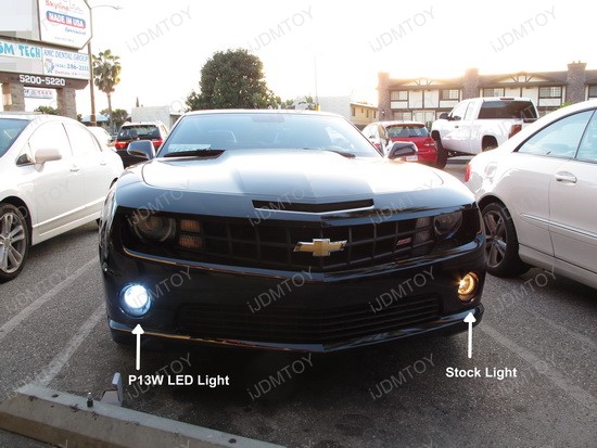
For the fog light signal, I tapped into the 12V wire on the fog lights. Because I added HID ballasts, there was no modification to the stock harness. If a ballast isn't used, a simple wire tap would do the job with little modification to the stock wire.
Here is the schematic for the switch. It uses one Single Pole Single Throw 12V relay (on the right) and one Double Pole Double Throw 12V relay (on the left).
This is the "Off" state.

With 0V applied to the circuit, all of the relays are off and all of the lights are disconnected from their power source.
This is the DRL state:
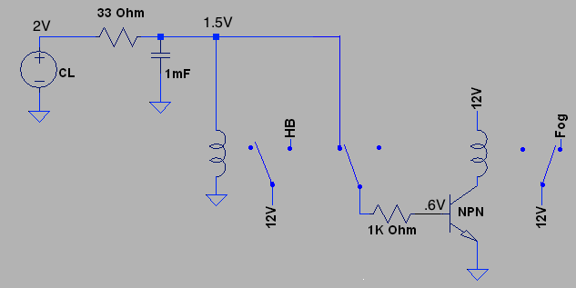
When 2V is applied, the 12V DPDT relay does not have enough current to turn on. The signal is routed through the relay to a npn transistor that is setup like a switch. The transistor only needs a Vbe of .6V to turn on. Once turned on, the current is pulled from the 12V supply through the SPST relay and then from the collector through the emmiter to ground. This turns on the SPST relay which will connect the 12V supply to the fog lights. Thus, a 2V CL will turn on the fog lights.
*Note* For whatever reason, the DRLs are run with an AC signal riding on a DC offset. My voltmeter read 2V DC and 4V AC. Others have said that the AC is typically RMS, but I think it is peak to peak due to it being a car. This would mean that the voltage on the CL is swinging from 4V to 0V. When first applied, I did not use the 33 ohm resistor and 1 mF cap. The swing was enough to switch my DPDT relay on and off and would not turn on my transistor. Adding the resistor and cap essentially adds a passive low pass filter with a -3 dB corner at, what I calculated to be, ~5 hz. I do not know what the frequency of the AC signal was. This low pass filter will block all high frequency parts of the signal and will allow the 2V DC through to the rest of the circuit. Adding the series resistor does cause a voltage divider with the relay coil which is why you see 1.5V past the filter. The 1.5V was calculated using the 100 ohm coil resistance of the DPDT relay. On a bench supply, the 1.5V was actually measured to be higher, but the ideal situation is close enough for current/power considerations.
Here is the high beam state:

When 12V is applied to the CL, the DPDT relay turns on. This disconnects the transistor switch from the CL, and at the same time, it connects the 12V supply to the high beams.
*Note* The 9V at the relay is calculated the same as the 1.5V previously. On the bench I measured ~10.5V meaning that the coil resistance of the relay is higher than spec'ed. Since the relay turns on around 6V, it did not make a difference in the application.
So, now when my car turns on the DRLs, my fogs turn on. When the lights are on, the DRL is turned off. Since the fog line of my circuit is tied to the stock fog 12V supply, the normal stock fog function remains unchanged.

If you have any questions, feel free to ask. If anyone plans to build this circuit, please let me know so that the current/power considerations can be calculated. This will save your car from having a fire in the engine bay.
Overall, I spent on the order of $40, but that included parts that were damaged in testing or were not needed. The schematic supplied is the most simple form I can come up with, and I believe all of the parts can be procured for less than $30.
If I please, I can disconnect this circuit and plug the stock bulbs and harnesses back in to return the car to stock with no damage to parts. This was the main reason for building the switch the way I did.
I bought a H7 harness to get the signal from the stock plug without any splicing. The harness came with a 12V relay and two H7 harnesses to plug into the high beams.
For the fog light signal, I tapped into the 12V wire on the fog lights. Because I added HID ballasts, there was no modification to the stock harness. If a ballast isn't used, a simple wire tap would do the job with little modification to the stock wire.
Here is the schematic for the switch. It uses one Single Pole Single Throw 12V relay (on the right) and one Double Pole Double Throw 12V relay (on the left).
This is the "Off" state.
With 0V applied to the circuit, all of the relays are off and all of the lights are disconnected from their power source.
This is the DRL state:
When 2V is applied, the 12V DPDT relay does not have enough current to turn on. The signal is routed through the relay to a npn transistor that is setup like a switch. The transistor only needs a Vbe of .6V to turn on. Once turned on, the current is pulled from the 12V supply through the SPST relay and then from the collector through the emmiter to ground. This turns on the SPST relay which will connect the 12V supply to the fog lights. Thus, a 2V CL will turn on the fog lights.
*Note* For whatever reason, the DRLs are run with an AC signal riding on a DC offset. My voltmeter read 2V DC and 4V AC. Others have said that the AC is typically RMS, but I think it is peak to peak due to it being a car. This would mean that the voltage on the CL is swinging from 4V to 0V. When first applied, I did not use the 33 ohm resistor and 1 mF cap. The swing was enough to switch my DPDT relay on and off and would not turn on my transistor. Adding the resistor and cap essentially adds a passive low pass filter with a -3 dB corner at, what I calculated to be, ~5 hz. I do not know what the frequency of the AC signal was. This low pass filter will block all high frequency parts of the signal and will allow the 2V DC through to the rest of the circuit. Adding the series resistor does cause a voltage divider with the relay coil which is why you see 1.5V past the filter. The 1.5V was calculated using the 100 ohm coil resistance of the DPDT relay. On a bench supply, the 1.5V was actually measured to be higher, but the ideal situation is close enough for current/power considerations.
Here is the high beam state:
When 12V is applied to the CL, the DPDT relay turns on. This disconnects the transistor switch from the CL, and at the same time, it connects the 12V supply to the high beams.
*Note* The 9V at the relay is calculated the same as the 1.5V previously. On the bench I measured ~10.5V meaning that the coil resistance of the relay is higher than spec'ed. Since the relay turns on around 6V, it did not make a difference in the application.
So, now when my car turns on the DRLs, my fogs turn on. When the lights are on, the DRL is turned off. Since the fog line of my circuit is tied to the stock fog 12V supply, the normal stock fog function remains unchanged.
If you have any questions, feel free to ask. If anyone plans to build this circuit, please let me know so that the current/power considerations can be calculated. This will save your car from having a fire in the engine bay.
Overall, I spent on the order of $40, but that included parts that were damaged in testing or were not needed. The schematic supplied is the most simple form I can come up with, and I believe all of the parts can be procured for less than $30.
If I please, I can disconnect this circuit and plug the stock bulbs and harnesses back in to return the car to stock with no damage to parts. This was the main reason for building the switch the way I did.
Thread Starter
Senior Moderator
Joined: Dec 2010
Posts: 31,897
Likes: 7,251
From: Austin, TX
I added a power diode to the DPDT relay but did not have a good place to put one on the SPST. We'll see if the transistor holds up. The reason I melted my first transistor was due to the lack of a base input resistance. Hence, the 1K ohm in series with the base of the NPN.
Like Carbon mentioned, adding a diode across the relay coil gives the current built up in the inductor of the coil a place to escape without killing your components. It would look like this.
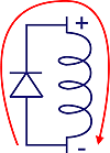
Some relays come with diodes built in and some don't. Find out because it will cause the relay to have a polarity to account for.
Like Carbon mentioned, adding a diode across the relay coil gives the current built up in the inductor of the coil a place to escape without killing your components. It would look like this.
Some relays come with diodes built in and some don't. Find out because it will cause the relay to have a polarity to account for.
Last edited by oo7spy; Nov 7, 2011 at 02:36 PM.


I think for lay people who don't understand electrical diagrams, some pictures would help? Good job though man. I have a basic understanding of electricity but not enough to play around in the RL due to high costs of repairs. I would like to do this but I probably wont add HID's. If you dont mind, shoot me a PM ir reply here with all that I need. Again, good work
Thread Starter
Senior Moderator
Joined: Dec 2010
Posts: 31,897
Likes: 7,251
From: Austin, TX
*NOTE* My previous mention of an H7 harness should be 9005 harness.
A picture of my board would be of little help to you. It would only make things more confusing. This project will require a soldering iron and a decent knowledge of following schematics. Rarely does everything work the first time it is plugged in, so a power supply outside of your car would be a great help but isn't vital to doing this project. That said, I have done the dirty work, designing and testing, and all that is left is to procure and connect the components correctly.
Here is the board I used to solder everything down.
http://www.radioshack.com/product/in...uctId=2103799#

Here is the 9005 harnesses and SPST relay used. I had to cut and splice the wires to configure it the way I needed, but it gives you the high beam harness to plug into the car, the two 9005 harnesses for the high beam bulbs, and a fused SPST relay for the 12V supply.
http://www.ebay.com/itm/160646836983...84.m1497.l2649
The other components can all be found at Radio Shack including a project enclosure to house everything.
Depending on the coil resistance of your DPDT relay, the current capacity of the wires and power rating of the resistors may change. I calculated the current of the high beams to be 4.58A each. I get this from P = V*I. The bulbs are 55W and are run at 12V, so I = 55W/12V = 4.58A. Thus, your DPDT relay needs to be able to carry 10 or more amps through its contacts to power both bulbs. I actually elected to use two relays with 5A ratings for each high beam. They are the exact same as these: http://www.radioshack.com/product/in...rodsPerPage=60 When I first designed this I thought I would need two DPDT relays and that is why I got two of these. You will only need one DPDT. If you cannot find a 10A DPDT, one 5A DPDT and one 5A SPST or SPDT will work as well. Everything will depend on what you can get. Also the relays I used are DIP components so they plug into the board linked above. Make sure the relays you get can be soldered to a board you can get.
If someone knows the actual current usage of a 55W bulb and wants to correct this, it would be appreciated.
I will not admit that this is the most simple or straightforward project. Soldering is an art and takes practice to do well. However, I think anyone who is technically minded can finish this successfully. Let me know if you want more info. I will help anyone who wants to give it a try.
As for your concern about RL repairs, there is nothing about this circuit that will damage the car's components. I did short out the CL while debugging and connected the fog line to ground while plugging it all in. Both times, each fuse blew like it should have to protect the car. This literally can be a plug an play component (except for tapping into the fog light).
A picture of my board would be of little help to you. It would only make things more confusing. This project will require a soldering iron and a decent knowledge of following schematics. Rarely does everything work the first time it is plugged in, so a power supply outside of your car would be a great help but isn't vital to doing this project. That said, I have done the dirty work, designing and testing, and all that is left is to procure and connect the components correctly.
Here is the board I used to solder everything down.
http://www.radioshack.com/product/in...uctId=2103799#
Here is the 9005 harnesses and SPST relay used. I had to cut and splice the wires to configure it the way I needed, but it gives you the high beam harness to plug into the car, the two 9005 harnesses for the high beam bulbs, and a fused SPST relay for the 12V supply.
http://www.ebay.com/itm/160646836983...84.m1497.l2649
The other components can all be found at Radio Shack including a project enclosure to house everything.
Depending on the coil resistance of your DPDT relay, the current capacity of the wires and power rating of the resistors may change. I calculated the current of the high beams to be 4.58A each. I get this from P = V*I. The bulbs are 55W and are run at 12V, so I = 55W/12V = 4.58A. Thus, your DPDT relay needs to be able to carry 10 or more amps through its contacts to power both bulbs. I actually elected to use two relays with 5A ratings for each high beam. They are the exact same as these: http://www.radioshack.com/product/in...rodsPerPage=60 When I first designed this I thought I would need two DPDT relays and that is why I got two of these. You will only need one DPDT. If you cannot find a 10A DPDT, one 5A DPDT and one 5A SPST or SPDT will work as well. Everything will depend on what you can get. Also the relays I used are DIP components so they plug into the board linked above. Make sure the relays you get can be soldered to a board you can get.
If someone knows the actual current usage of a 55W bulb and wants to correct this, it would be appreciated.
I will not admit that this is the most simple or straightforward project. Soldering is an art and takes practice to do well. However, I think anyone who is technically minded can finish this successfully. Let me know if you want more info. I will help anyone who wants to give it a try.
As for your concern about RL repairs, there is nothing about this circuit that will damage the car's components. I did short out the CL while debugging and connected the fog line to ground while plugging it all in. Both times, each fuse blew like it should have to protect the car. This literally can be a plug an play component (except for tapping into the fog light).
Trending Topics


Instructor
Joined: May 2012
Posts: 231
Likes: 61
From: Ann Arbor, MI
This doesn't seem to match up with the spec sheet on the DPDT relay you linked to, which says the pickup voltage is 9.6V. It also specifies that the dropout is 0.6V, which seems awful close to your voltage in the DRL case. Am I missing something?
Last edited by IanVS; Jul 2, 2012 at 11:37 AM.
Thread Starter
Senior Moderator
Joined: Dec 2010
Posts: 31,897
Likes: 7,251
From: Austin, TX
Well, notice that I measured 10.5V on the bench using a 12V supply, so I am well above the pickup voltage. Also, with the car running, the supply will be 13 and change.
As for the drop out voltage, my DRL case is 1.5V (~1.7-2V actual). With a 12V supply (battery only), the relay turns off. I have encountered cases where it won't turn off when driving probably due to the alternator's 13V supply, so my relay's dropout voltage seems to be somewhere around 2V. Do keep in mind that Radio Shack stocks some of the worst components, so the accuracy of their datasheet is questionable.
I would really like to rebuild the circuit with a PCB and some automotive components for increased reliability. Someday I will do that, but for now, the prototype works.
Instructor
Joined: May 2012
Posts: 231
Likes: 61
From: Ann Arbor, MI

Thread Starter
Senior Moderator
Joined: Dec 2010
Posts: 31,897
Likes: 7,251
From: Austin, TX
When I do, I will build a few. In order to buy custom PCBs cheap, you have to buy 10 or so. No promises on when that happens, though. I have already missed about 3 dates I told theNBP I would make. 

Advanced
Joined: May 2012
Posts: 63
Likes: 5

Thread Starter
Senior Moderator
Joined: Dec 2010
Posts: 31,897
Likes: 7,251
From: Austin, TX
Haha. The prototype has issues in cold temperatures. I think it is due to a shitty decoupling capacitor. I have been brainstorming ways to improve, but those darn relays are so sensitive. I will build another some day, and hopefully when I do, I will build 5 or so. I think I have abandoned the custom PCB route, though.
I'll update accordingly.
I'll update accordingly.
Advanced
Joined: May 2012
Posts: 63
Likes: 5
Haha. The prototype has issues in cold temperatures. I think it is due to a shitty decoupling capacitor. I have been brainstorming ways to improve, but those darn relays are so sensitive. I will build another some day, and hopefully when I do, I will build 5 or so. I think I have abandoned the custom PCB route, though.
I'll update accordingly.
I'll update accordingly.

Thread Starter
Senior Moderator
Joined: Dec 2010
Posts: 31,897
Likes: 7,251
From: Austin, TX
I think I came up with a better design. The prototype has issues a high as 60 degrees. The only thing that makes sense having a sensitivity to cold like that is the capacitor. However, you can't just add more or else the high beam response suffers.
I'll try to draw up my new idea and SPICE model it.
I'll try to draw up my new idea and SPICE model it.
Advanced
Joined: May 2012
Posts: 63
Likes: 5
Thread Starter
Senior Moderator
Joined: Dec 2010
Posts: 31,897
Likes: 7,251
From: Austin, TX

Originally Posted by Texas Transportation Code, � 547.328. FOG LAMPS PERMITTED.
(a) A motor vehicle may be equipped with not more than two fog lamps. (b) A fog lamp shall be: (1) mounted on the front of the vehicle at a height from 12 to 30 inches; and (2) aimed so that no part of the high-intensity portion of the beam from a lamp mounted to the left of center on a vehicle projects a beam of light at a distance of 25 feet that is higher than four inches below the level of the center of the lamp. (c) Lighted fog lamps may be used with lower headlamp beams as specified by Section 547.333.


The fog light code was written WAY before DRLs existed. With their introduction, the line between the two has become extremely blurred. I have been pulled over since installing the switch. As soon as I stopped, I killed the car. You know, to "put the LEO at ease". Coincidentally, the DRLs shut off with the car.
 He checked the front of the car, didn't see anything, and moved on.
Is it a potential risk? Sure. Is the risk significant? IMO, no. If the cop wants to be a dick, we can pull out the books on DRL laws, draw the line on their definition with the judge, and go from there.
Safety Car
Joined: Sep 2005
Posts: 3,920
Likes: 421
Thread Starter
Senior Moderator
Joined: Dec 2010
Posts: 31,897
Likes: 7,251
From: Austin, TX
Many American cars can. I know Ford Rangers in particular come stock with the ability. FWIW, it is also illegal to drive with your parking lights only, but who really cares.
Safety Car
Joined: Sep 2005
Posts: 3,920
Likes: 421
Heavy - did you mean parking lights?
I know it is illegal to drive with parking lights on - they are for parking.
Pretty sure you are supposed to have your low beams on with fog lights, i.e., no driving with fog lights only
I know it is illegal to drive with parking lights on - they are for parking.
Pretty sure you are supposed to have your low beams on with fog lights, i.e., no driving with fog lights only
parking lights = running lights = red & amber
Either way I was wrong, here's the guidance for VA inspectors (19VAC30-70-160) with irrelevant stuff removed.
The check for the fogs being wired into low beams is in section 11 (g) subsection (1)
Full Text Here
Either way I was wrong, here's the guidance for VA inspectors (19VAC30-70-160) with irrelevant stuff removed.
The check for the fogs being wired into low beams is in section 11 (g) subsection (1)
Full Text Here
19VAC30-70-160. Auxiliary lamps: backup; cornering; driving; fog; spot and warning.
A. Auxiliary lamps on a vehicle consist of seven general types: backup lamps (SAE-R), cornering lamps (SAE-K), driving lamps (SAE-Y), front fog lamps with an amber or clear lens (SAE-F and rear fog lamps with red lens (SAE-F2), spot lamps (SAE-O), warning lamps (SAE-W, W2, W3), and daytime running lamps (DRLs) (SAE-Y2).
C. There is no limit on the number of backup lamps that a vehicle may have so long as they are of an approved type (SAE-R).
D. No more than four lamps, including two headlamps, may be lighted at any time to provide general illumination ahead of the vehicle.
I. Inspect for and reject if:
� 46.2-1165 of the Code of Virginia.
A. Auxiliary lamps on a vehicle consist of seven general types: backup lamps (SAE-R), cornering lamps (SAE-K), driving lamps (SAE-Y), front fog lamps with an amber or clear lens (SAE-F and rear fog lamps with red lens (SAE-F2), spot lamps (SAE-O), warning lamps (SAE-W, W2, W3), and daytime running lamps (DRLs) (SAE-Y2).
C. There is no limit on the number of backup lamps that a vehicle may have so long as they are of an approved type (SAE-R).
D. No more than four lamps, including two headlamps, may be lighted at any time to provide general illumination ahead of the vehicle.
I. Inspect for and reject if:
1. Vehicle has an auxiliary lamp being used for a purpose other than for which it was approved.
EXCEPTION: Any lighting device that is both covered and not illuminated, other than lamps required, shall not be considered for inspection. Fog and driving lamps mounted below the level of the regular headlamps must be checked for aim as outlined in subdivisions I 10 i and 11 g of this section if not covered.
NOTE: The covers shall be a type that would be installed as original equipment and not tape, paper bags, aluminum foil or similar materials per subdivision I 11g (2).
2. A vehicle has installed on it a warning lamp (DOT or SAE-W) that is not of an approved type or has been altered.
Reject if the vehicle has wire, unapproved plastic covers, any other materials that are not original equipment or any colored material placed on or in front of any auxiliary lamps: backup, cornering, driving, fog, spot, or warning lamps.
3. Vehicle is equipped with a combination of auxiliary lamps that include more than two fog lamps, or more than two spot lamps, or more than two driving lamps. Motor vehicles may be equipped with more than two fog or auxiliary lights; however, only two of these types of lights can be illuminated at any time. Reject a vehicle equipped with a headlamp mounted or used as an auxiliary lamp.
NOTE: Vehicles equipped, from the factory, with two driving lamps should not be rejected.
4. Vehicle is equipped with an auxiliary lamp that does not function properly. (If an auxiliary lamp has been modified by removing the wiring, bulb and socket, the unit will be considered an ornament and not a lamp and will not be considered in inspection.)
6. Any lamp is not of an approved type or if lamps to be burned together as a pair do not emit the same color light.
7. The lens has a piece broken from it. The lens may have one or more cracks provided an off-color light does not project through the crack or cracks.
10. Driving lamps are not required. However, if installed they must operate and be inspected.
Inspect for and reject if:
NOTE: DRLs may or may not be wired into the tail light circuit.
Inspect for and reject if:
a. Any lamp, except headlamps, used as DRLs if not an approved type (SAE-Y2) and is not marked "DRL";
b. Fog lamps or parking lamps are used as DRLs;
c. More than one pair of lamps is used and/or designated as DRLs;
d. A DRL is mounted higher than 34 inches measured to the center of the lamp;
e. The color is other than white to amber;
f. DRLs do not deactivate when the headlamps are in any "on" position.
Any DRL optically combined with a turn signal or hazard lamp must deactivate when the turn signal or hazard lamp is activated and then reactivate when the turn signal or hazard lamp deactivates.
Statutory AuthorityEXCEPTION: Any lighting device that is both covered and not illuminated, other than lamps required, shall not be considered for inspection. Fog and driving lamps mounted below the level of the regular headlamps must be checked for aim as outlined in subdivisions I 10 i and 11 g of this section if not covered.
NOTE: The covers shall be a type that would be installed as original equipment and not tape, paper bags, aluminum foil or similar materials per subdivision I 11g (2).
2. A vehicle has installed on it a warning lamp (DOT or SAE-W) that is not of an approved type or has been altered.
Reject if the vehicle has wire, unapproved plastic covers, any other materials that are not original equipment or any colored material placed on or in front of any auxiliary lamps: backup, cornering, driving, fog, spot, or warning lamps.
3. Vehicle is equipped with a combination of auxiliary lamps that include more than two fog lamps, or more than two spot lamps, or more than two driving lamps. Motor vehicles may be equipped with more than two fog or auxiliary lights; however, only two of these types of lights can be illuminated at any time. Reject a vehicle equipped with a headlamp mounted or used as an auxiliary lamp.
NOTE: Vehicles equipped, from the factory, with two driving lamps should not be rejected.
4. Vehicle is equipped with an auxiliary lamp that does not function properly. (If an auxiliary lamp has been modified by removing the wiring, bulb and socket, the unit will be considered an ornament and not a lamp and will not be considered in inspection.)
6. Any lamp is not of an approved type or if lamps to be burned together as a pair do not emit the same color light.
7. The lens has a piece broken from it. The lens may have one or more cracks provided an off-color light does not project through the crack or cracks.
10. Driving lamps are not required. However, if installed they must operate and be inspected.
Inspect for and reject if:
a. Driving lamps are installed on vehicles equipped with the four-headlamp system, except the "F" type headlamp system;
b. A vehicle is equipped with more than two driving lamps;
c. Driving lamps are not of an approved type or have been altered;
d. The color of the lamp is other than white;
e. The lens has a piece broken from it or is rotated away from its proper position. The lens may have one or more cracks provided an off-color light does not project through the crack or crack;
f. Wiring or electrical connections are defective;
g. Any driving lamp is mounted above the level of the regular headlamps, or is not mounted firmly to prevent excessive vibration;
h. Driving lamps are not wired so that they will burn only when the high beams of the regular headlamps are activated;
i. Driving lamps are not aimed so that the center of the hot spot drops three inches in 25 feet so that the hot spot is directly ahead of the lamp;
NOTE: Driving lamps must be aimed using the optical headlight aimer. A tolerance of four inches in 25 feet is allowed in both the horizontal and the vertical adjustment.
11. Fog lamps are not required. However, if installed they must operate and be inspected.b. A vehicle is equipped with more than two driving lamps;
c. Driving lamps are not of an approved type or have been altered;
d. The color of the lamp is other than white;
e. The lens has a piece broken from it or is rotated away from its proper position. The lens may have one or more cracks provided an off-color light does not project through the crack or crack;
f. Wiring or electrical connections are defective;
g. Any driving lamp is mounted above the level of the regular headlamps, or is not mounted firmly to prevent excessive vibration;
h. Driving lamps are not wired so that they will burn only when the high beams of the regular headlamps are activated;
i. Driving lamps are not aimed so that the center of the hot spot drops three inches in 25 feet so that the hot spot is directly ahead of the lamp;
NOTE: Driving lamps must be aimed using the optical headlight aimer. A tolerance of four inches in 25 feet is allowed in both the horizontal and the vertical adjustment.
Inspect for and reject if:
a. A vehicle is equipped with more than two fog lamps;
b. Lamps are not of an approved type (DOT or SAE-F on front or F2 on rear plus two-digit year and manufacturer) or a lamp has been altered;
c. The lens is other than clear or amber. Fog lamps may have black-end bulbs or small metal caps over the end of the bulb;
d. The lens has a piece broken from it or is rotated away from its proper position. The lens may have one or more cracks provided an off-color light does not project through the crack or crack;
e. Wiring or electrical connections are defective or filaments do not burn;
f. Any fog lamp is mounted above the level of the regular headlamps, or is not mounted firmly;
g. Lamps are not wired and aimed according to the following instructions:
(1) Fog lamps are general illumination lamps as covered in subsection A of this section. They must burn through the tail light circuit even if on a separate switch. If installed on a vehicle with a four-headlamp system, or a vehicle equipped with driving lamps, they must be wired into the low beam circuit.
(2) Fog lamps must be aimed so that the top edge of the high intensity zone is set at the horizontal centerline and the left edge of the high intensity zone is set at the vertical centerline. (Same as low beam headlights.)
NOTE: Fog lamps must be aimed using the optical headlight aimer. A tolerance of four inches in 25 feet is allowed in both the horizontal and the vertical adjustment.
13. Daytime Running Lamps (DRLs) are not required. However, if installed they must operate and be inspected. DRLs must be installed in pairs.a. A vehicle is equipped with more than two fog lamps;
b. Lamps are not of an approved type (DOT or SAE-F on front or F2 on rear plus two-digit year and manufacturer) or a lamp has been altered;
c. The lens is other than clear or amber. Fog lamps may have black-end bulbs or small metal caps over the end of the bulb;
d. The lens has a piece broken from it or is rotated away from its proper position. The lens may have one or more cracks provided an off-color light does not project through the crack or crack;
e. Wiring or electrical connections are defective or filaments do not burn;
f. Any fog lamp is mounted above the level of the regular headlamps, or is not mounted firmly;
g. Lamps are not wired and aimed according to the following instructions:
(1) Fog lamps are general illumination lamps as covered in subsection A of this section. They must burn through the tail light circuit even if on a separate switch. If installed on a vehicle with a four-headlamp system, or a vehicle equipped with driving lamps, they must be wired into the low beam circuit.
(2) Fog lamps must be aimed so that the top edge of the high intensity zone is set at the horizontal centerline and the left edge of the high intensity zone is set at the vertical centerline. (Same as low beam headlights.)
NOTE: Fog lamps must be aimed using the optical headlight aimer. A tolerance of four inches in 25 feet is allowed in both the horizontal and the vertical adjustment.
NOTE: DRLs may or may not be wired into the tail light circuit.
Inspect for and reject if:
a. Any lamp, except headlamps, used as DRLs if not an approved type (SAE-Y2) and is not marked "DRL";
b. Fog lamps or parking lamps are used as DRLs;
c. More than one pair of lamps is used and/or designated as DRLs;
d. A DRL is mounted higher than 34 inches measured to the center of the lamp;
e. The color is other than white to amber;
f. DRLs do not deactivate when the headlamps are in any "on" position.
Any DRL optically combined with a turn signal or hazard lamp must deactivate when the turn signal or hazard lamp is activated and then reactivate when the turn signal or hazard lamp deactivates.
� 46.2-1165 of the Code of Virginia.


Thread
Thread Starter
Forum
Replies
Last Post
xsilverhawkx
2G TL Problems & Fixes
5
Sep 28, 2015 06:51 PM