When you click on links to various merchants on this site and make a purchase, this can result in this site earning a commission. Affiliate programs and affiliations include, but are not limited to, the eBay Partner Network.
This post gives some insight about how to do the resistor trick, but I'm having trouble comprehending what to do.
"You need a 8K resistor and a 2K resistor. The 8K resistor goes between the center pin and gnd. The 2K resistor goes between the center pin and VCC. This is on the sensor. On the motor-side, just put a 10W 3-ohm resistor between the two pins."
Is there anyone around that has done this that might be willing to help out, or has any knowledge on electronics/circuitry? I can solder, but when it comes to ohms or voltages, or any actual circuitry, I'm completely dumb.
I could just have the VSA TB plugged in and left out to the side, but that kinda irks me out. I've got a big box of resistors, so I might just play around with it until I figure something out, and if I do end up getting it done, I'll post some pics of what I got done.
Those folks are long gone.
I believe you are going to have to 'go with' that little bit of quote information and experiment to find any answers.
If you can figure out a way to apply the resistors, in an easy way before committing to a final solder, that would make the process faster keeping all OEM connections intact should you have to abandon the effort.
I know they're gone, I've tried contacting them, lol. Some has a video of their VSA delete, but they just removed the lights from the dash. I still want to pass emissions testing, and a CEL with fail me.
I made another thread in hopes that some one might know what to do. Maybe I'll be that person. Suppose we'll see.
Maybe find a large female side Acura / honda connector, at the salvage yard, and de-pin it. Use the pins to solder the 8K & 2K resistors, as per the above quote, then attach to the corresponding male pins or visa versa on the sensor. Doing the same with the 10W 3-ohm resistor, on the motor side, making them easy to install and remove for testing?
Maybe find a large female side Acura / honda connector, at the salvage yard, and de-pin it. Use the pins to solder the 8K & 2K resistors, as per the above quote, then attach to the corresponding male pins or visa versa on the sensor. Doing the same with the 10W 3-ohm resistor, on the motor side, making them easy to install and remove for testing?
My kit didn't come with 8k resistors. It was a 25 variety pack, so I have to configure multiple resistors to get close to 8k, so that's issue one.
Issue two is knowing which ones to even put where in the plug. I don't even know what they meant by 'VCC'.
Issue three is that I don't know what they mean by "on the motor side". I only have 2 plugs that aren't connected, unless they mean one of the two plugs is the 'motorside' plug. I still need to get a 10W 3ohm resistor as well.
Also, when I was doing the whole top plate for the IMRC wiring, it was impossible to get the pins out of the connector without using a drill and ruining the hole. I only did it on the 3 plugs I didn't need, but I was hoping to get the two out for a little more contact for soldering the wires. You have any tips for getting them out? I tried every which way with a small tool.
At the engine in what way though? Is it one of the two plugs, or a wire going from one of the plugs to the engine? I was also thinking they meant motor side as in the motor on the VSA TB that actually turns the throttle plate.
And I have a tool set meant for tiny screws that just has a poker type tip that I thought would work, but it didn't. Is there not a certain maneuver I can do with it to come out?
My kit didn't come with 8k resistors. It was a 25 variety pack, so I have to configure multiple resistors to get close to 8k, so that's issue one.
Issue two is knowing which ones to even put where in the plug. I don't even know what they meant by 'VCC'.
Issue three is that I don't know what they mean by "on the motor side". I only have 2 plugs that aren't connected, unless they mean one of the two plugs is the 'motorside' plug. I still need to get a 10W 3ohm resistor as well.
If you have the PDF Helms service manual for the CL-S, when you type vcc into the 'find' function, for instance, vcc comes up a lot in pin-out diagrams for connectors. If you can isolate the pin-out infor for the relevant VSA connectors, that may help your cause. Not sure if it is even there, though. You may need the 'electrical' manual for the car?
In addition, the Helms has a whole VSA section from page 19-144 through 19-231. You may find the information you need to formulate a by-pass to the VSA there, based on the quote info above?
Also, when I was doing the whole top plate for the IMRC wiring, it was impossible to get the pins out of the connector without using a drill and ruining the hole. I only did it on the 3 plugs I didn't need, but I was hoping to get the two out for a little more contact for soldering the wires. You have any tips for getting them out? I tried every which way with a small tool.
If you have the PDF Helms service manual for the CL-S, when you type vcc into the 'find' function, for instance, vcc comes up a lot in pin-out diagrams for connectors. If you can isolate the pin-out infor for the relevant VSA connectors, that may help your cause. Not sure if it is even there, though. You may need the 'electrical' manual for the car?
In addition, the Helms has a whole VSA section from page 19-144 through 19-231. You may find the information you need to formulate a by-pass to the VSA there, based on the quote info above?
It's been a struggle to get my hands on a 3 ohm 10 watt resistor, but it finally came. I've got everything hooked up and working. No VSA light, and the switch still works to turn it off. I don't know what will happen if it's left on and traction control kicks in. I imagine it'd just blow the resistors or a fuse. Everything about the TCS should still work, just not the throttle body portion since it's gone.
I don't recommend you doing this unless you upgrade your TB size like I did, because safety is more important.
I cut the plug off of the VSA motor for the throttle body plate, and simply soldered on the 10w3o to the wires. There is no particular direction it needs to be attached. I covered up the connections with shrink tubing. I didn't want the wires flopping about, so I used some duck tape to make everything snug. Looks ugly, but it gets the job done.
I didn't have an 8k resistor in my box, so I had to combine two resistors that came out to about 7.8k. The resistors have a 5%+/- though, so it's not a huge deal. I shrink wrapped it and the the 2k resistor.
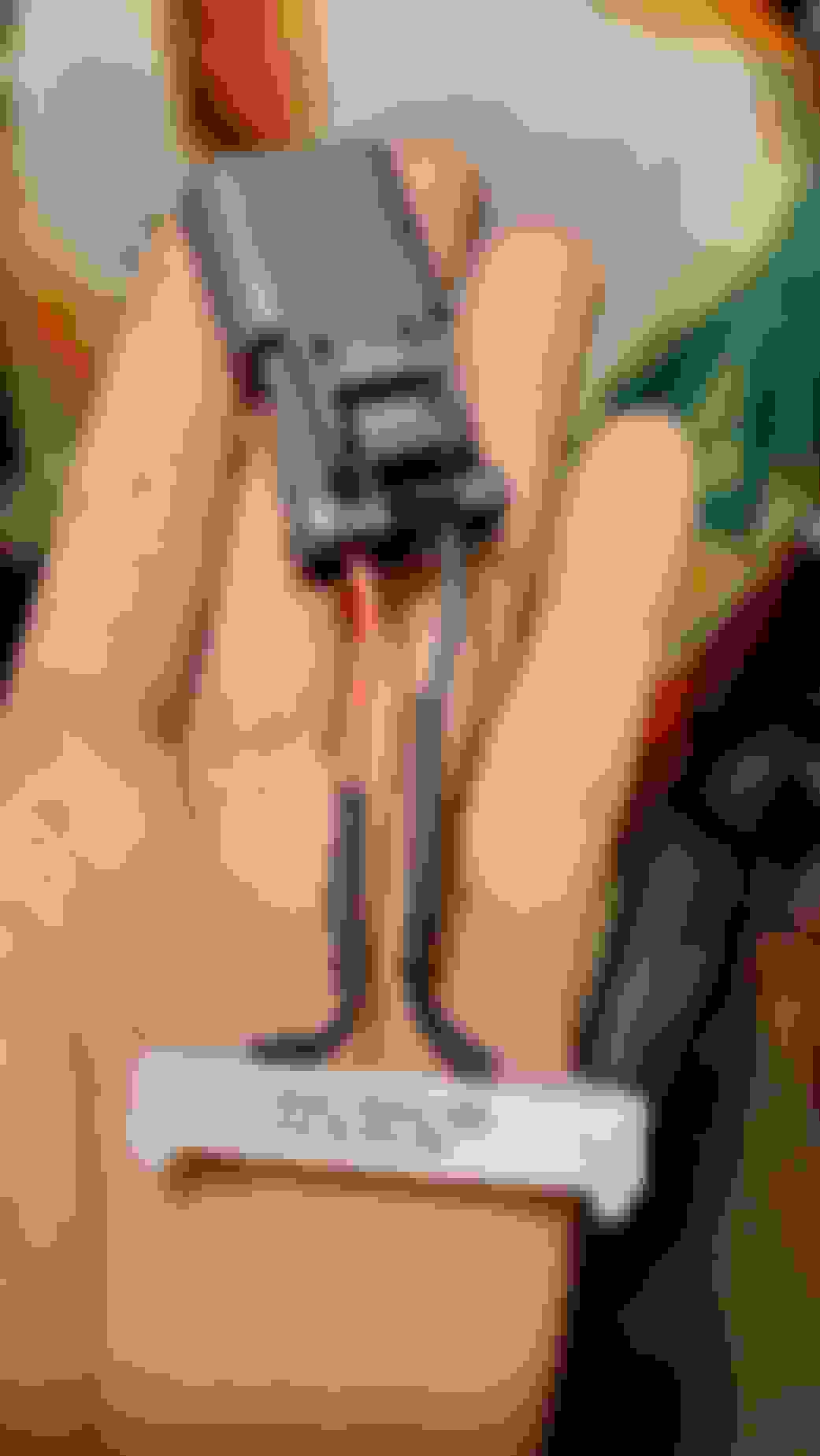
I left the leads to the plug on for testing before dedicating the connections with solder. This was the main issue I was worried when originally reading the post on this. There were no pics. I've labeled everything so you can tell what goes where.
Once I confirmed everything worked, I cut the plug's lead's off (with extra wire in case I need to put them back on), and soldered the resistors together. Shrink wrapped everything. It came out pretty ugly, but again, it gets the job done.
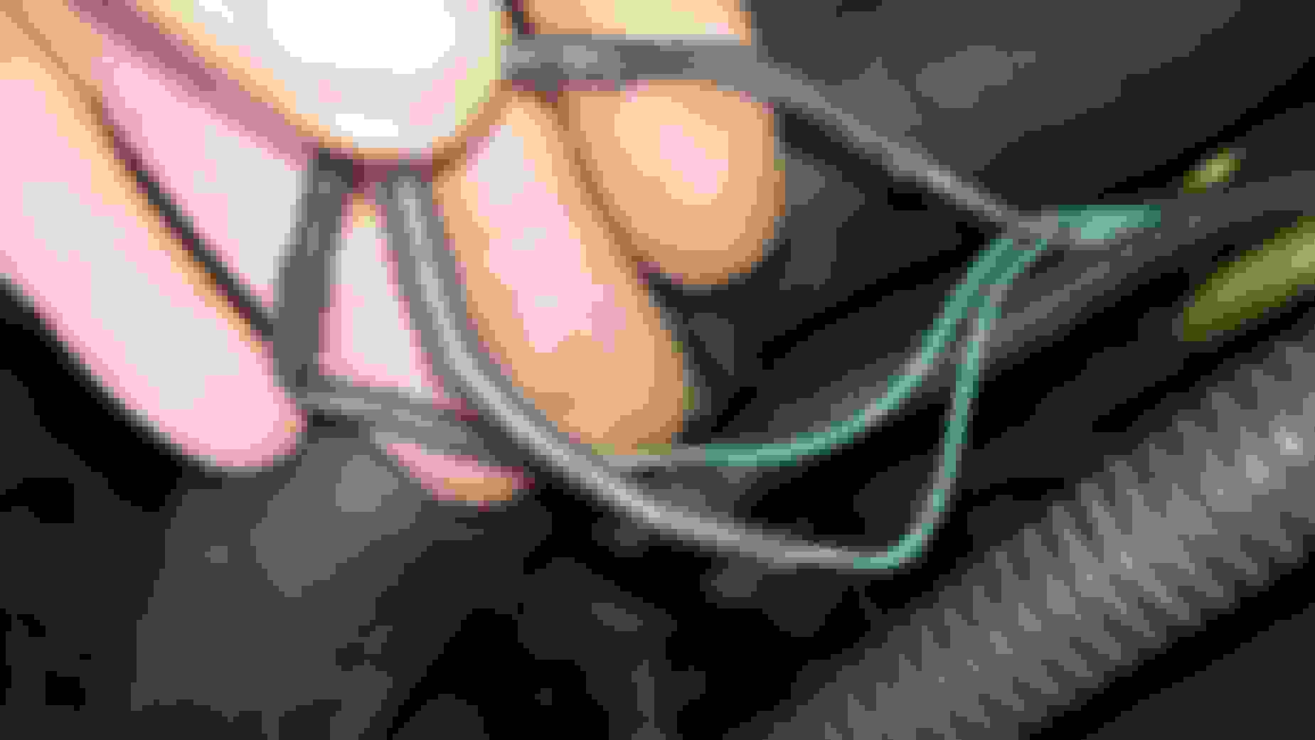
This is the motor side plug all connected and hooked up to the old VSA bracket.
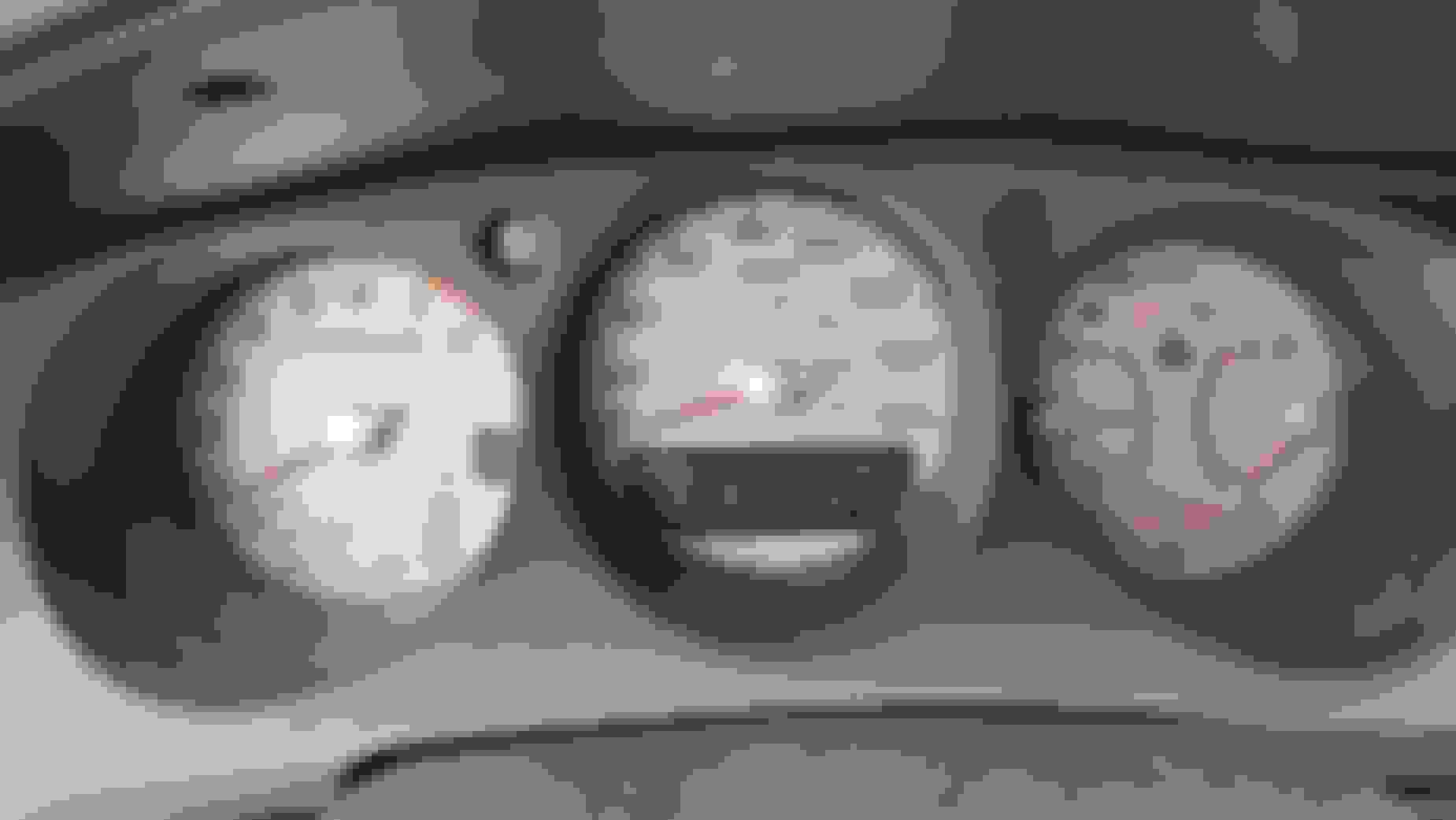
No VSA light! Hoorah! Don't judge my mileage.
After everything was all said done, I wrapped the TCS wires around the EGR wire so it won't flop around everywhere.
There you have it. Extremely simple. I was just stressing over what wire was what. Now to move on to fixing some issues on my car.
I don't know what will happen if it's left on and traction control kicks in. I imagine it'd just blow the resistors or a fuse. Everything about the TCS should still work, just not the throttle body portion since it's gone.
Nice job and pictures on how it all connects!
You are probably the only active member left here (CL side) to give this a try.
If anyone stumbles across this information on the 2G TL side, maybe there will be two.
As you know, one day when you inadvertently or purposefully? accelerate through some sand / gravel is possibly when you'll have a situation to trip the traction control function.
As a result, let us know what happens should the dash light up.
I'd be interested to hear what you experience, if anything at all.
Well, I was tempted to test it via a good ol' burn out, but I broke one of the two resistor's leads and had to redo it, so now I'm left with one. I'm not keen on busting that resistor with how long it took to get my hands on those big boys.
That said, they do mention in the thread what happens:
typeR's Avatar typeR , 01-18-2006 03:48 PM Senior Moderator
Quote:
Originally Posted by allmotor_2000 However I suggest you disable VSA when trying to race.
i mentioned that above and can attest that the car will still try to stop the wheel spin...im not sure if it fuel cuts ...but when i hit it hard from a dead stop as soon as signifigant wheel spin occurs the car all but stalls and the dash lights up....this is temp as soon as you restart the car all lights are gone
So I guess after starting and stopping the car, or pulling the ECU fuse, it'd dissapear. Still don't want to test it though.
I also made a video in case anyone is looking for this fix on there.

 03-25-2021 | 05:19 PM