
DIY: Hard Disk to DVD Navigation Conversion
 05-13-2014, 02:31 PM
#1
Racer
Thread Starter
DIY: Hard Disk to DVD Navigation Conversion
Forward
Step 5: Depining and Stowing
Step 7: ILL - Grounding
Step 8: Finalizing the MUTE Wire
Hello Everyone,
This will be a DIY guide for how to convert the hard disk based navigation system into an OEM DVD based system. The hard disk systems are found in the 1996-1999 models, although I cannot confirm the earliest known model year that was equipped with Navigation. In 2000, Acura chose to use a DVD-based system. The DVD based systems are superior as the disc is able to contain maps on the entire continental united States. Additionally, after 1999, the navigation interface received a larger display.
The hard disk systems have been known to fail and after several years it is almost guaranteed. This leaves you with a few options. You may purchase a replacement card from the dealership for approximately $1300, this is the same type of drive and is likely to fail again, you may purchase a PCMIA card from navhelp for about $100 with the region you like, or you may convert the navigation system into a DVD based system. Option 1 is obviously out of the question for most people and assuming you don't mind spending a little more money and have the tech skills to do this DIY, the conversion, I believe is the best bet because you get the added benefits of maps of the entire US, as well as a larger screen. You may be able to find a set for $300 or so, eBay is a great place to look for this equipment.
My motivation for this is that there is no definitive guide online for this (until me, anyway!) and I'd just like to have a place for consolidated information on this project. Sometimes, too, you go online and people write only 2 or 3 sentences on the matter instead of 12 pages, so I want this to be the place to go.
There are rumors out there that you lose voice prompts and stuff like that. But if you follow my method, everything will work as designed, no features are sacrificed or lost.
Please be aware this is a very advanced project. There are quite a bit of steps and if you aren't paying attention there is a lot of room for error.
And of course, the disclaimer. Although I'm pretty sure I don't have to say this, but if you screw up your car by doing this and try to sue me, Acurazine, or your dog, whatever, you'll lose. You can cross wires while doing this project and either ruin your navigation system, stereo, CD changer, or air conditioner unit. Basically anything that runs on electricity is at risk when doing this project. It is highly recommended that you have experience with soldering and advanced analytical circuitry skills. Also, there may be a risk of fire if this modification is not done properly. Please take care when doing this project, if you feel this is too advanced for you, take your car to an automotive audio shop.
Anyway, I hope you enjoy!
Difficulty Level: Advanced
Table of ContentsThis will be a DIY guide for how to convert the hard disk based navigation system into an OEM DVD based system. The hard disk systems are found in the 1996-1999 models, although I cannot confirm the earliest known model year that was equipped with Navigation. In 2000, Acura chose to use a DVD-based system. The DVD based systems are superior as the disc is able to contain maps on the entire continental united States. Additionally, after 1999, the navigation interface received a larger display.
The hard disk systems have been known to fail and after several years it is almost guaranteed. This leaves you with a few options. You may purchase a replacement card from the dealership for approximately $1300, this is the same type of drive and is likely to fail again, you may purchase a PCMIA card from navhelp for about $100 with the region you like, or you may convert the navigation system into a DVD based system. Option 1 is obviously out of the question for most people and assuming you don't mind spending a little more money and have the tech skills to do this DIY, the conversion, I believe is the best bet because you get the added benefits of maps of the entire US, as well as a larger screen. You may be able to find a set for $300 or so, eBay is a great place to look for this equipment.
My motivation for this is that there is no definitive guide online for this (until me, anyway!) and I'd just like to have a place for consolidated information on this project. Sometimes, too, you go online and people write only 2 or 3 sentences on the matter instead of 12 pages, so I want this to be the place to go.
There are rumors out there that you lose voice prompts and stuff like that. But if you follow my method, everything will work as designed, no features are sacrificed or lost.
Please be aware this is a very advanced project. There are quite a bit of steps and if you aren't paying attention there is a lot of room for error.
And of course, the disclaimer. Although I'm pretty sure I don't have to say this, but if you screw up your car by doing this and try to sue me, Acurazine, or your dog, whatever, you'll lose. You can cross wires while doing this project and either ruin your navigation system, stereo, CD changer, or air conditioner unit. Basically anything that runs on electricity is at risk when doing this project. It is highly recommended that you have experience with soldering and advanced analytical circuitry skills. Also, there may be a risk of fire if this modification is not done properly. Please take care when doing this project, if you feel this is too advanced for you, take your car to an automotive audio shop.
Anyway, I hope you enjoy!
Difficulty Level: Advanced
Equipment and Tools
Theory
Step 2: Preparing the Console Controls
Step 3: Navigation Computer Conversion
Step 4: Running the Wires
Step 5: Depining and Stowing
Step 6: Adding Pins
Step 7: ILL - Grounding
Step 8: Finalizing the MUTE Wire
Step 9: Fog Light Switch
Step 10: Rear Defroster Switch
Step 11: Fit Adjustments
Conclusion
Equipment and ToolsTheory
Problem 1: Navigation Computer Connectors
Problem 2: Extra Wires in Navigation Interface/Radio
Problem 3: Missing Pins in Original Harness Connectors for Newer System
Problem 4: Rear Defroster Switch
Step 1: Preparing the RearProblem 2: Extra Wires in Navigation Interface/Radio
Problem 3: Missing Pins in Original Harness Connectors for Newer System
Problem 4: Rear Defroster Switch
Step 2: Preparing the Console Controls
Step 3: Navigation Computer Conversion
Step 4: Running the Wires
Step 5: Depining and Stowing
Step 6: Adding Pins
Step 7: ILL - Grounding
Step 8: Finalizing the MUTE Wire
Step 9: Fog Light Switch
Step 10: Rear Defroster Switch
Step 11: Fit Adjustments
Conclusion
Navigation Interface from 2000-2003 (2004 will NOT work)
2nd Generation (Black Disc) DVD Navigation Computer
Radio from 2000-2003
Air Conditioner Console from 2000-2003
Hazard and Fog Light Switches from 2000-2003
Connectors from Each of the Above Elements
Screwdrivers (Phillips and Flathead, Preferably)
Precision Screwdriver Set
Metric Sockets and Drive
Door Panel Remover Tool
Wire Cutters
Soldering Iron and Solder
Volt Meter
Sewing Needle
Wire
Heat Shrink
Heat Shrink Shielded Tubing Terminations
Grounding Terminal
Electrical Tape
Zip Ties
Wiring Diagrams/Pinouts2nd Generation (Black Disc) DVD Navigation Computer
Radio from 2000-2003
Air Conditioner Console from 2000-2003
Hazard and Fog Light Switches from 2000-2003
Connectors from Each of the Above Elements
Screwdrivers (Phillips and Flathead, Preferably)
Precision Screwdriver Set
Metric Sockets and Drive
Door Panel Remover Tool
Wire Cutters
Soldering Iron and Solder
Volt Meter
Sewing Needle
Wire
Heat Shrink
Heat Shrink Shielded Tubing Terminations
Grounding Terminal
Electrical Tape
Zip Ties
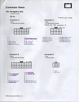
Please download and print the wiring diagrams/pinouts I've consolidated here.
TheoryIn this section, I will go into the theory of why exactly it is we are doing what I have outlined in this DIY. I strongly recommend you consider the theory behind this project, not only for the educational value, but it will help ensure you know what you are doing and will reduce the likelihood of making a mistake. Bear in mind, this project took me about 5 hours of just looking at wiring diagrams and pinout configurations before I even got started on the conversion itself. Additionally, I had my father, a degreed electrical engineer crosscheck my work.
If you are going to understand this, there are no shortcuts; you will have to print out the diagrams yourself and go through the same process I did. I will not describe every single element of every single diagram I have in this section, but I will talk about the problems that arise during the conversion process and how to resolve them.
Should you decide to go straight to the DIY below, that is fine, too. If though, for whatever reason, your system is slightly different, you are responsible for whatever goes wrong.
Problem 1: Navigation Computer Connectors
Step 1: Preparing the RearThe connectors between the hard disk and DVD computers are different. As you may see on the pinout diagrams, not only are the shapes of the connectors different, but the DVD based system has 3 extra wires that are nonexistent on the older models. These three wires are a mute wire, power wire, and taillight relay wire.
So in short, the hard disk computer has 20 wires leaving it whereas the DVD computer has 23 wires. The MUTE wire is ran to the radio, this is related to the voice output command signals. The power wire (AMP SW +B) is ran to the amplifier and tied in. When observing the wiring diagrams, and comparing the two systems, you will notice that from the computer, the AMP SW +B wire has to be tied into this line. And lastly, the tail light relay wire (ILL +) is tied into the right tail light.
All other wires have an equivalent between the systems, as I illustrate in my personal notes below. What we will do is repin the connectors and run three additional wires into for the system from the computer in the trunk.
This exact steps for the resolution are described in detail later on.

Problem 2: Extra Wires in Navigation Interface/RadioSo in short, the hard disk computer has 20 wires leaving it whereas the DVD computer has 23 wires. The MUTE wire is ran to the radio, this is related to the voice output command signals. The power wire (AMP SW +B) is ran to the amplifier and tied in. When observing the wiring diagrams, and comparing the two systems, you will notice that from the computer, the AMP SW +B wire has to be tied into this line. And lastly, the tail light relay wire (ILL +) is tied into the right tail light.
All other wires have an equivalent between the systems, as I illustrate in my personal notes below. What we will do is repin the connectors and run three additional wires into for the system from the computer in the trunk.
This exact steps for the resolution are described in detail later on.
In the older display interface, there are three wires that leave it that are not accounted for in the newer display. These wires are the AUDIO BUS +, AUDIO BUS -, and AUDIO BUS SH wires. They help control the voice prompts for the system.
In the older radio unit, too, there are two extra wires that are nonexistent in the newer radio. These wires are the AUDIO BUS + and AUDIO BUS - wires. They come from the display interface.
Since these wires are not used in the newer model, they will be capped and stowed later on; this will allow us to be able to revert to the older system if ever necessary.
Problem 3: Missing Pins in Original Harness Connectors for Newer SystemIn the older radio unit, too, there are two extra wires that are nonexistent in the newer radio. These wires are the AUDIO BUS + and AUDIO BUS - wires. They come from the display interface.
Since these wires are not used in the newer model, they will be capped and stowed later on; this will allow us to be able to revert to the older system if ever necessary.
On the radio for the newer system, there is a MUTE wire (same as from the trunk) that does not exist in the original system. Also, there is a SH AUDIO GU wire that is nonexistent. These wires will have to be added into the car so that the newer system can work as designed with them. The wiring diagrams and pinouts will clearly show why. I would like to add, too, that the system will work without the shied wires installed (SH *Whatever*), I did not add them, but I put the contact pins in anyway and stowed them.
Additionally, in the display interface, two wires will have to be added to the existing harness. These wires are the ILL - and SH DISPLAY BUS wires.
Both of these wires will be taken from pins out of the connectors of the newer unit and placed into the existing connectors for their respective locations.
It is necessary to use the newer radio with these modifications as the insides are completely different and one is designed to operate and expect the certain signals provided by components of the newer system.
Problem 4: Rear Defroster SwitchAdditionally, in the display interface, two wires will have to be added to the existing harness. These wires are the ILL - and SH DISPLAY BUS wires.
Both of these wires will be taken from pins out of the connectors of the newer unit and placed into the existing connectors for their respective locations.
It is necessary to use the newer radio with these modifications as the insides are completely different and one is designed to operate and expect the certain signals provided by components of the newer system.
In the newer model air conditioner units, there is one extra wire that is leaving it that the older one does not have. Thankfully, though, all the connectors and other pinouts are exactly the same as the other one. So here, because this is the hot wire for the rear defroster, we will integrate that into preexisting switch.
First, we will want to remove several parts off of the car to facilitate the conversion process.
Remove the lower portion of the back seat by pulling the black tab on each side that is directly aft of each front seat. The tabs pull forward and you can then lift up and pull forward on the seat. Place the seat out of the way somewhere.
Afterwards, remove the vertical portion of the back seat by removing the 6 #10 bolts that hold it to the cabin. There are four bolts on the bottom and one behind each headrest. Place with other seat portion.
Then there are four black screw clips that hold the piece of carpet immediately aft of the rear seat onto the base of trunk. Remove these and keep somewhere safe, along with the bolts you just removed, and then also place the piece of carpet out of the way.
This will all make your life quite a bit easier when having to work back there.
You should see something like this now:


Now you will want to remove the door sill trim on the front passenger and rear passenger seats. This is where the door panel remover will come in handy. After that, you can easily lift of the carpet and expose the harness underneath.
You ought to see something like this:


Step 2: Preparing the Console ControlsRemove the lower portion of the back seat by pulling the black tab on each side that is directly aft of each front seat. The tabs pull forward and you can then lift up and pull forward on the seat. Place the seat out of the way somewhere.
Afterwards, remove the vertical portion of the back seat by removing the 6 #10 bolts that hold it to the cabin. There are four bolts on the bottom and one behind each headrest. Place with other seat portion.
Then there are four black screw clips that hold the piece of carpet immediately aft of the rear seat onto the base of trunk. Remove these and keep somewhere safe, along with the bolts you just removed, and then also place the piece of carpet out of the way.
This will all make your life quite a bit easier when having to work back there.
You should see something like this now:
Now you will want to remove the door sill trim on the front passenger and rear passenger seats. This is where the door panel remover will come in handy. After that, you can easily lift of the carpet and expose the harness underneath.
You ought to see something like this:
Here we will be getting the console area ready for the conversion process. This is a relatively easy part, but it helps to just have it ready to go for when the time comes. All you will need here is a phillips screwdriver.
You will start with something like this:

Now remove the black plastic trim around the shifter by just prying up on it with your fingernails, no need for tools here. This is what you should see:

Next, remove the woodgrain trim around the shifter. Again, just pull up. Be careful, though not to snap it. And be sure to unplug the connector that goes into the trim. You should now see this:

This next bit requires a little finesse. We will now be removing the vent piece above the navigation unit. Carefully reach in with your fingernails or a small screwdriver and pry it out. Your console should now look like this:

There are four screws (two on top and two on bottom) that need to be removed to free the whole console tower. The cup holder is a great place to keep these to make sure they don't get lost on you.
Do not unplug any of the electronics as we will need to use them to find a particular wire later on. Just leave them like this.
Step 3: Navigation Computer ConversionYou will start with something like this:
Now remove the black plastic trim around the shifter by just prying up on it with your fingernails, no need for tools here. This is what you should see:
Next, remove the woodgrain trim around the shifter. Again, just pull up. Be careful, though not to snap it. And be sure to unplug the connector that goes into the trim. You should now see this:
This next bit requires a little finesse. We will now be removing the vent piece above the navigation unit. Carefully reach in with your fingernails or a small screwdriver and pry it out. Your console should now look like this:
There are four screws (two on top and two on bottom) that need to be removed to free the whole console tower. The cup holder is a great place to keep these to make sure they don't get lost on you.
Do not unplug any of the electronics as we will need to use them to find a particular wire later on. Just leave them like this.
Here we will be changing out the computer unit. This part is relatively straightforward, but there is a lot of room for mistakes. Using my personal notes above of the pinouts, we will repin each pin of the older unit into the connector from the DVD unit.
First remove the navigation computer unit by simply taking off the bolts that keep it on.
Now we will want to very carefully start the repining process.
I strongly recommend that you only do one connector at a time for each one. If you start pulling all of these pins out, you'll have a bad time. So for instance, as I illustrate above, pin A4 on the older unit (what is existing in your wiring harness now) should be placed into pin slot B7 on the connector for the DVD. Always triple check that you are indeed taking out the correct wire and putting it in the right slot.
For actually pulling the pins out, it is quite easy. Opposite of the large tab on the connector are little white rectangles that you can see through the outer piece. Take a small screwdriver and push those tabs up towards the large tab on top of the connector. This allows the pins to be pulled out with ease, just be careful not to let them all try to come out on you, they should have a decent friction fit sitll.
Remember, Connector B on the older model is the same as connector C for the newer one, no repining is necessary here.
Here is a table of pin conversions:

Push the big tab down now to secure the pins you have just put in place. Make sure, too, that they are all the way pushed forward to ensure a good connection.
Your connectors should now be similar to this:

Please note in the above that I have an extra red wire and orange wire, you should not have these in yet. They are for the MUTE wire and AMP SW +B wire. We will be running these later, at the time of the photograph I did not have the tail light relay wire run yet.
You may now bolt on the DVD based computer system, but leave the rear seat apart, I took these photos a little bit out of order and the rear seat must remain removed for the time being.

Step 4: Running the WiresFirst remove the navigation computer unit by simply taking off the bolts that keep it on.
Now we will want to very carefully start the repining process.
I strongly recommend that you only do one connector at a time for each one. If you start pulling all of these pins out, you'll have a bad time.
So for instance, as I illustrate above, pin A4 on the older unit (what is existing in your wiring harness now) should be placed into pin slot B7 on the connector for the DVD. Always triple check that you are indeed taking out the correct wire and putting it in the right slot.For actually pulling the pins out, it is quite easy. Opposite of the large tab on the connector are little white rectangles that you can see through the outer piece. Take a small screwdriver and push those tabs up towards the large tab on top of the connector. This allows the pins to be pulled out with ease, just be careful not to let them all try to come out on you, they should have a decent friction fit sitll.
Remember, Connector B on the older model is the same as connector C for the newer one, no repining is necessary here.
Here is a table of pin conversions:
Push the big tab down now to secure the pins you have just put in place. Make sure, too, that they are all the way pushed forward to ensure a good connection.
Your connectors should now be similar to this:
Please note in the above that I have an extra red wire and orange wire, you should not have these in yet. They are for the MUTE wire and AMP SW +B wire. We will be running these later, at the time of the photograph I did not have the tail light relay wire run yet.
You may now bolt on the DVD based computer system, but leave the rear seat apart, I took these photos a little bit out of order and the rear seat must remain removed for the time being.
In this bit, we will be running the 3 additional wires we need from the navigation computer. Remember, these are the AMP SW +B wire, MUTE wire, and ILL+ wire.
AMP SW +B Wire
We will be taking care of the AMP SW +B wire first.
This is the section why we left the console controls plugged in up front.
First locate the bundle of wires that we will be tying into for the AMP SW +B wire. Thanks to my dad for taking pictures of this part, I would have forgot! Here is where it's located:

This is it upon closer inspection. Again, do not mind the red and orange wires, this photograph was taken after I ran the wires already.

Now remove the electrical tape around the harness:

Now, this is where things can go wrong. We are looking for the yellow and blue (YEL/BLU) wire that is identified in the picture below. There may be another wire that is similar to this, but this is not the one you want. After locating the single yellow and blue wire, make contact with the conductor by pressing the sewing needle into it. Connect the needle to the volt meter and measure for 12 Volts DC. Verify that this it the correct wire by looking for 12 V when the radio is on and that it reads 0 V when the radio is off. This is how you know you have the right wire. Now we have to tie into it.

Solder and heat shrink one end of the wire into the one we identified.
Now begin running the wire backwards into the trunk, following the wiring harness, and once you get it there, you may cut that end of the wire from the spool. So now, you should have a wire tied in from the location in the backseat to the navigation computer now.
Now tie into the pin A-8 that should have a length of wire waiting for it. After soldering it in, apply heat shrink for insulation.
Okay, 1 down, 2 to go!
This is the section why we left the console controls plugged in up front.
First locate the bundle of wires that we will be tying into for the AMP SW +B wire. Thanks to my dad for taking pictures of this part, I would have forgot! Here is where it's located:
This is it upon closer inspection. Again, do not mind the red and orange wires, this photograph was taken after I ran the wires already.
Now remove the electrical tape around the harness:
Now, this is where things can go wrong. We are looking for the yellow and blue (YEL/BLU) wire that is identified in the picture below. There may be another wire that is similar to this, but this is not the one you want. After locating the single yellow and blue wire, make contact with the conductor by pressing the sewing needle into it. Connect the needle to the volt meter and measure for 12 Volts DC. Verify that this it the correct wire by looking for 12 V when the radio is on and that it reads 0 V when the radio is off. This is how you know you have the right wire. Now we have to tie into it.
Solder and heat shrink one end of the wire into the one we identified.
Now begin running the wire backwards into the trunk, following the wiring harness, and once you get it there, you may cut that end of the wire from the spool. So now, you should have a wire tied in from the location in the backseat to the navigation computer now.
Now tie into the pin A-8 that should have a length of wire waiting for it. After soldering it in, apply heat shrink for insulation.
Okay, 1 down, 2 to go!
MUTE Wire
Now we will do the MUTE wire.
Basically, we will be running a wire all the way from the computer unit in the trunk all the way to the radio.
So in order to do this, have someone hold (or just tape) one end at the computer. Then start running the wire towards the amplifier, following the harness for the navigation system along side the passenger side of the vehicle all the way to the front passenger multiplex control unit area (front passenger footwell). I used aircraft wiring string tie to attach it to the harness, but for most people, zip ties are much easier. Additionally, it is a good idea to run the wire inside the corrugated tubing if you can. It takes some time to do it like this, but it produces very professional results.
Once you get to the glove box, you will have to remove the white panel underneath it as well as the kick panel that covers the multiplex control unit.
This is a bit what it looks like:

Also, you will have to remove the panel shown below to make room for running the wire. Don't mind all the other wires I have coming off of it as they are other unrelated projects I've done.

You may now remove the old console tower from your car by simply unplugging all the connectors behind it. It is a good idea to label each connector and where it came from.

Run your MUTE wire to the center console area. Make sure to mark it as the MUTE wire.

Terminate your MUTE wire into Connector B, Pin 3 in the DVD computer unit. Again, there should be a wire waiting for it. After soldering, add heat shrink for insulation.
Your connectors in the trunk will now look like this:
That's 2 for 3, just one more!
Basically, we will be running a wire all the way from the computer unit in the trunk all the way to the radio.
So in order to do this, have someone hold (or just tape) one end at the computer. Then start running the wire towards the amplifier, following the harness for the navigation system along side the passenger side of the vehicle all the way to the front passenger multiplex control unit area (front passenger footwell). I used aircraft wiring string tie to attach it to the harness, but for most people, zip ties are much easier. Additionally, it is a good idea to run the wire inside the corrugated tubing if you can. It takes some time to do it like this, but it produces very professional results.
Once you get to the glove box, you will have to remove the white panel underneath it as well as the kick panel that covers the multiplex control unit.
This is a bit what it looks like:
Also, you will have to remove the panel shown below to make room for running the wire. Don't mind all the other wires I have coming off of it as they are other unrelated projects I've done.
You may now remove the old console tower from your car by simply unplugging all the connectors behind it. It is a good idea to label each connector and where it came from.
Run your MUTE wire to the center console area. Make sure to mark it as the MUTE wire.
Terminate your MUTE wire into Connector B, Pin 3 in the DVD computer unit. Again, there should be a wire waiting for it. After soldering, add heat shrink for insulation.
Your connectors in the trunk will now look like this:
That's 2 for 3, just one more!
ILL + Wire
This is the last wire we have to run.
This wire is used so the computer can detect whether or not the headlights are on.
Starting from the computer unit, solder into B-8. Again place heat shrink over it for insulation.

Now we will be running the wire into the tail light on the passenger side of the vehicle.
After running the ILL + Wire through the tubing until it gets to the carpet, run it behind the carpet to the left tail light. You will need to remove a couple tabs to be able to move the carpet. Thanks again to my dad for posing for this picture!

Now tie it into the wire shown below. For this part I used one of the saddleback connectors that I've described in one of my other DIYs. Although if you've made it this far, you probably know what you're doing and can do it however you want.

This wire is used so the computer can detect whether or not the headlights are on.
Starting from the computer unit, solder into B-8. Again place heat shrink over it for insulation.
Now we will be running the wire into the tail light on the passenger side of the vehicle.
After running the ILL + Wire through the tubing until it gets to the carpet, run it behind the carpet to the left tail light. You will need to remove a couple tabs to be able to move the carpet. Thanks again to my dad for posing for this picture!
Now tie it into the wire shown below. For this part I used one of the saddleback connectors that I've described in one of my other DIYs. Although if you've made it this far, you probably know what you're doing and can do it however you want.
As I described above, there are certain wires we will have to depin and stow because they are no longer needed. We are stowing these so that, should we ever have to revert back to the older system we may. In the pictures for this section, don't mind the added wires yet, I took the picture after I had done that bit; right now just worry about the contact pins we are pulling out.
In the same way you removed pins from the connectors at the computer we will be doing this in the center console area.
On the existing radio Connector C, depin C-6 (AUDIO BUS +) and C-12 (AUDIO BUS -). Once the pins are out, ensure to push the large tab back down on the connector so the rest do not come out. Take these wires and fold them back onto the harness and wrap electrical tape around them.

Now, we have to depin and stow 3 wires from the display unit connector. Depin A-3 (AUDIO BUS +), A-4 (AUDIO BUS SHIELD), and A-13 (AUDIO BUS -). Again, fold these back on the harness and wrap electrical tape around it to keep it from shorting anything out.

Step 6: Adding PinsIn the same way you removed pins from the connectors at the computer we will be doing this in the center console area.
On the existing radio Connector C, depin C-6 (AUDIO BUS +) and C-12 (AUDIO BUS -). Once the pins are out, ensure to push the large tab back down on the connector so the rest do not come out. Take these wires and fold them back onto the harness and wrap electrical tape around them.
Now, we have to depin and stow 3 wires from the display unit connector. Depin A-3 (AUDIO BUS +), A-4 (AUDIO BUS SHIELD), and A-13 (AUDIO BUS -). Again, fold these back on the harness and wrap electrical tape around it to keep it from shorting anything out.
Radio
The older model's connectors on the radio and navigation unit each lack 2 pins.
On the radio, Connector C lacks C-7 (MUTE) as well as C-11 (SH AUDIO GU).
As we have manipulated the pins before, obtain the wire and pin contact from the newer unit connector and install them into their respective locations in the existing connector.
Remember the idea is that we are making the existing connector match the one that came off the new system.
This is what the connector should now look like:
If you like, you may not install or stow the SH AUDIO GU wire, as it is not really necessary.
Display
Now we have to do the same thing for the navigation display connector.
The navigation display connector on the older models lack A-12 (ILL -) and A-14 (SH DISP BUS).
Again, from the connector off the newer unit remove those two wires and install them into existing connector.
If you like, you may not install the SH DISP BUS wire, as it is not really necessary.

The navigation display connector on the older models lack A-12 (ILL -) and A-14 (SH DISP BUS).
Again, from the connector off the newer unit remove those two wires and install them into existing connector.
If you like, you may not install the SH DISP BUS wire, as it is not really necessary.
Climate Control Console
Again, same thing for the climate control console.
Connect B on the existing harness, in pin 11, lacks the YEL/GRN wire for the rear defroster. Simply remove the pin from the connector off of the newer system and pin it into the existing connector.
Connect B on the existing harness, in pin 11, lacks the YEL/GRN wire for the rear defroster. Simply remove the pin from the connector off of the newer system and pin it into the existing connector.
Here, we have to ground the ILL - wire that we obtain from the newer connector.
Now, take a small length of wire (approximately 2 ft. or so) and on one end install a grounding terminal on it. Also, ground it onto the bolt shown in the picture below.

Now take the other end and attach it to the ILL - wire from the navigation display (pin A-12).

Place heat shrink over the joint for insulation.
Now, take a small length of wire (approximately 2 ft. or so) and on one end install a grounding terminal on it. Also, ground it onto the bolt shown in the picture below.
Now take the other end and attach it to the ILL - wire from the navigation display (pin A-12).
Place heat shrink over the joint for insulation.
Here we are going to finish up with the MUTE wire.
On the wire now coming from Connector C on the radio, simply join the two ends together:

Step 9: Fog Light SwitchOn the wire now coming from Connector C on the radio, simply join the two ends together:
This is another pretty easy part.
The switches between the two models are actually electronically the same, except the sizes of the casings are different.
This is to show that they are identical:

So what we will do is repin the connector.
First take one of the precision screwdrivers and lift up the little holder tab as shown below. Do this to both of the connectors.

Now, all there is to it is to take a paperclip and stick it into the top part of the whole from the front side and once you here it click, the wire pulls right out.
Swap the wires one for one for the new connector and make sure it fits and works.

Step 10: Rear Defroster SwitchThe switches between the two models are actually electronically the same, except the sizes of the casings are different.
This is to show that they are identical:
So what we will do is repin the connector.
First take one of the precision screwdrivers and lift up the little holder tab as shown below. Do this to both of the connectors.
Now, all there is to it is to take a paperclip and stick it into the top part of the whole from the front side and once you here it click, the wire pulls right out.
Swap the wires one for one for the new connector and make sure it fits and works.
Here we will address the final issue that is the rear defroster switch.
The old system and new system behave pretty much exactly the same way. On the old system switch, there are 6 wires, 2 for the indicator light, 2 for the backlight, and 2 for the signal. Of the signal wires, one provides a ground for the system and one is the ground. The one we care about is no. 3, the YEL/BLU wire.
Because the newer air conditioner console has a wire on it that grounds the signal for us (B-11), we will join these two wires together.
We want to leave the other wires in because it allows us to go back if necessary and it is a convenient place to keep the wires from shorting against anything.
So for this step, solder the wire that goes into the air conditioner unit into the end of the wire that went into the old switch. I soldered at the base of the contact pin so as not to mess it up too bad.
Again, place heat shrink over it for insulation, too.
Step 11: Fit AdjustmentsThe old system and new system behave pretty much exactly the same way. On the old system switch, there are 6 wires, 2 for the indicator light, 2 for the backlight, and 2 for the signal. Of the signal wires, one provides a ground for the system and one is the ground. The one we care about is no. 3, the YEL/BLU wire.
Because the newer air conditioner console has a wire on it that grounds the signal for us (B-11), we will join these two wires together.
We want to leave the other wires in because it allows us to go back if necessary and it is a convenient place to keep the wires from shorting against anything.
So for this step, solder the wire that goes into the air conditioner unit into the end of the wire that went into the old switch. I soldered at the base of the contact pin so as not to mess it up too bad.
Again, place heat shrink over it for insulation, too.
I apologize for not having any pictures for this section, I left the memory card out and I thought I was taking pictures when the camera was really not storing them.
I will try my best to describe what is going on here.
We have to adjust some of the surfaces to make the console fit into the older space.
The first thing that needs to go is the felt covered bar at the top near the air vent. It was too much of a pain to use a 90 degree screwdriver to get it out, so I took Dremel tool with a cutting bit and just cut it off where the screws went in.
Also, directly under the edges of that are two plastic tabs that have a bit of leather over them. Using pliers, just break those plastic tabs off. These bits interfere with the hazard lights switch and fog lights switch when going in.
There are two tabs on the bottom that the trim around the shifter goes into. They are at the bottom of the console stack and the front of the trim piece, near the cigarette lighter. I used a sanding bit to take those down almost to the top of the square opening.
Lastly, on the left side of the new trim, I used a sanding bit on the Dremel tool to knock down the back from the top of the trim to about halfway down the hazard lights switch. You also have to knock down the trim around the instrument cluster a bit, too.
It's important to use your best judgement here and fit check it quite often.
You can always remove material but you cannot add onto it again.
Just take your time on this step, it's easy to get into a hurry because once this part is done, you may go back together with everything!
ConclusionI will try my best to describe what is going on here.
We have to adjust some of the surfaces to make the console fit into the older space.
The first thing that needs to go is the felt covered bar at the top near the air vent. It was too much of a pain to use a 90 degree screwdriver to get it out, so I took Dremel tool with a cutting bit and just cut it off where the screws went in.
Also, directly under the edges of that are two plastic tabs that have a bit of leather over them. Using pliers, just break those plastic tabs off. These bits interfere with the hazard lights switch and fog lights switch when going in.
There are two tabs on the bottom that the trim around the shifter goes into. They are at the bottom of the console stack and the front of the trim piece, near the cigarette lighter. I used a sanding bit to take those down almost to the top of the square opening.
Lastly, on the left side of the new trim, I used a sanding bit on the Dremel tool to knock down the back from the top of the trim to about halfway down the hazard lights switch. You also have to knock down the trim around the instrument cluster a bit, too.
It's important to use your best judgement here and fit check it quite often.
You can always remove material but you cannot add onto it again.
Just take your time on this step, it's easy to get into a hurry because once this part is done, you may go back together with everything!
Go back together with everything now as took it apart! Be careful not to fowl anything up when you are going back with the console, e.g. makes sure wires do not get pinched. I certainly hope someone finds this of use. If you have any questions let me know and I'll try my best to answer you.
 05-13-2014, 02:38 PM
#2
Racer
Thread Starter
Wiring Diagrams/Pinouts
Here are the wiring diagrams and pinouts I have.
00-02 Nav Wiring Diagram.pdf
00-03 Nav Wiring Diagram.pdf
96-99 Nav Disaplay Troubleshoot.pdf
96-99 Nav Wiring Diagram.pdf
All Years Computer Pinout.pdf
All Years Display Pinout.pdf
All Years HVAC Pinout.pdf
All Years Radio Pinout.pdf
HVAC Wiring Diagram 1.pdf
00-02 Nav Wiring Diagram.pdf
00-03 Nav Wiring Diagram.pdf
96-99 Nav Disaplay Troubleshoot.pdf
96-99 Nav Wiring Diagram.pdf
All Years Computer Pinout.pdf
All Years Display Pinout.pdf
All Years HVAC Pinout.pdf
All Years Radio Pinout.pdf
HVAC Wiring Diagram 1.pdf
05-13-2014, 02:47 PM
#3
Racer
Thread Starter
More Wiring Diagrams/Pinouts
HVAC Wiring Diagram 2.pdf
Power Distribution.pdf
E 00-02 Nav Wiring Diagram.pdf
E 96-99 Nav Wiring Diagram.pdf
HVAC Wiring Diagram 2.pdf
Power Distribution.pdf
E 00-02 Nav Wiring Diagram.pdf
E 96-99 Nav Wiring Diagram.pdf
05-13-2014, 03:00 PM
#4
Racer
Thread Starter
Last Batch:
E All Years Display Pinout.pdf
E All Years HVAC Pinout.pdf
Some of them were a little large to attach, but all the originals made it up.

E All Years Display Pinout.pdf
E All Years HVAC Pinout.pdf
Some of them were a little large to attach, but all the originals made it up.

Thread
Thread Starter
Forum
Replies
Last Post
calrow
Car Parts for Sale
11
05-03-2017 10:21 PM
navtool.com
5G TLX Audio, Bluetooth, Electronics & Navigation
31
11-16-2015 08:30 PM