
G-109: DIY-Eliminate LED Bulb Induced Hyper flashing WITHOUT LOAD RESISTORS
 09-22-2011, 08:39 PM
#321

i just picked up a 08 tl yesterday night and i live in apex... you interested in meeting up? im in love with yours and i kinda wanna see what these leds look like in person... i'll throw you whatever you want to do the soddering n all that ... i joined yesterday so i dont have pm permission but if you want, hit me up at jerzydevil609(at)gmail(dot)com id really appreciate it... thanks pimpin hope to hear from you
thanks alot too to everybody else that contributed to this thread and i look forward to joinin the 3gen family n talkin with you guys n learnin about my new baby!! you'll probably see me askin alotta questions in the near future (post research of course haha)
 09-23-2011, 09:30 PM
#322
Cruisin'
Join Date: Sep 2010
Posts: 24
Likes: 0
Received 0 Likes
on
0 Posts
would like to also confirm this works 100% on 2008 acura tl-s. 4 led swap. 2x 12ohm resistors paralleled in the stock flasher. Also want to say thanks to Roger who found this easier method and sharing with us. Did a full led front and back swap out with soldering the resistors in 30 min. easy task to tackle for a waaaay cleaner look.
09-24-2011, 03:11 PM
#323
Burning Brakes
Got mine installed everything works great led switchbacks up front and led rear signals and no hyper flashing!
09-24-2011, 04:41 PM
#324
Burning Brakes
Little help please.. I noticed some of you guys are saying your running a .24ohm resistor if you have front and back leds? I just installed switchbacks up front and led turn signals in back and only used a 1watt .12ohm resistor ? everything blinks fine no hyper flashing. Is that going to overheat the circuit ? DO I need to swap that out for a .24???
09-24-2011, 05:16 PM
#326
Burning Brakes
09-24-2011, 06:39 PM
#327
Instructor

If anything it should build up less heat, as it's not resisting as much. Either way, the current isn't running through there the whole time you're driving, just when the blinkers are on. Also, it's just momentary while it checks if there is enough resistance in the line to activate the hyperflash or not.
09-24-2011, 07:39 PM
#328
hey MattB07TL just replied to your PM. I think its easiest to think of this resistor as like setting the temperature on a thermostat. Like a thermostat regulates the temperature based on the its set to, this resistor senses to current draw of the flasher circuit and dictates whether the relay flashes normal or enters into hyper flash mode.
If the system is drawings less power then the set point, hyper flashing is induced as a warning system, because under normal circumstances this means you have a bulb out. This might be obvious to most but I have a feeling some people may think its just a phenomena or a symptom of the electrical system (if that makes sense).
If the system is drawings less power then the set point, hyper flashing is induced as a warning system, because under normal circumstances this means you have a bulb out. This might be obvious to most but I have a feeling some people may think its just a phenomena or a symptom of the electrical system (if that makes sense).
09-27-2011, 07:17 PM
#330
OK I finally got my resistor in today (BIG THANKS TO XAVIER25)
DID NOT have a soldering gun or even held one until today.
I tried calling around to various computer shops in my area to ask if they can solder it and this is how it went.
1st place - "Oh I don't do soldering. I used to have a co-worker who did all the circuit board work, but he doesn't do it anymore"
2nd place - "Oh yes we do soldering, but we only solder computer and laptop parts, we can't solder anything outside of that due to liability purposes" (or some stupid BS)
3rd place - "No I don't do soldering, but let me try and get into contact with a friend who can possibly do it. Just call me back, leave me a voicemail saying what you need done, and I'll send the voicemail to my friend to get a price quote for you"
WTF? I did not expect for it to be such a PITA just to find a computer shop to solder this for me. Finally got fed up and looked online at radioshack for soldering guns.
Ended up purchasing http://www.radioshack.com/product/in...rodsPerPage=60.
Total was $25 after taxes.
Honestly, I didn't feel like I had enough experience or will to even attempt this myself. That's why I called other places. But after calling around and not getting anywhere for about 15 mins I just thought to myself "Fuck it, might as well learn on your own so you can do it in the future"
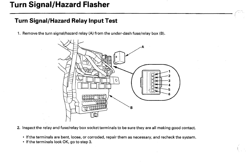
REMOVING THE TURN SIGNAL RELAY...
Taking out the turn signal relay was a little challenge... It's held in by a clip and there's 1 on each side (left and right) that hold it in. When I would be able to unclip one side, the other side would still be clipped in. When I would try and go to the other side to unclip it, than the opposite side that was previously unclipped would get clipped. I finally took a flat head screw driver and accidentally broke one of the clips on the right side (the clip that you can't see because it's facing towards the front of the car). I thought I was in trouble, but really all I did was make it ALOT easier to remove the turn signal relay. Trust me, I tried hard to properly pull out the turn signal relay without breaking anything, but amidst the frustration of the clips constantly snapping back in place when I would get one side out, and the 95F heat blazing on the back of my head, I decided to get a little rough with it and broke the clip lol.
REMOVING THE GREY PLASTIC HOUSING FROM THE RELAY..
Once I was able to remove the turn signal relay, I brought it inside to inspect it. On the exterior of the turn signal relay is a silver/grey-ish housing. No one explained how to remove this cover (well I skimmed the first 2-3 pages and found nothing). I took a very small flat head and jammed it in between the 2 different plastics and slowly pulled it up so it would unclip itself. This grey housing is also held in place by small clips. 2 on each side, a total of 4. First pry one side til its unclipped, than flip the turn signal relay over and do the same for the other side. Once both side is unclipped just use both hands and slowly remove the grey housing cover.
REMOVING THE OEM SHUNT RESISTOR..
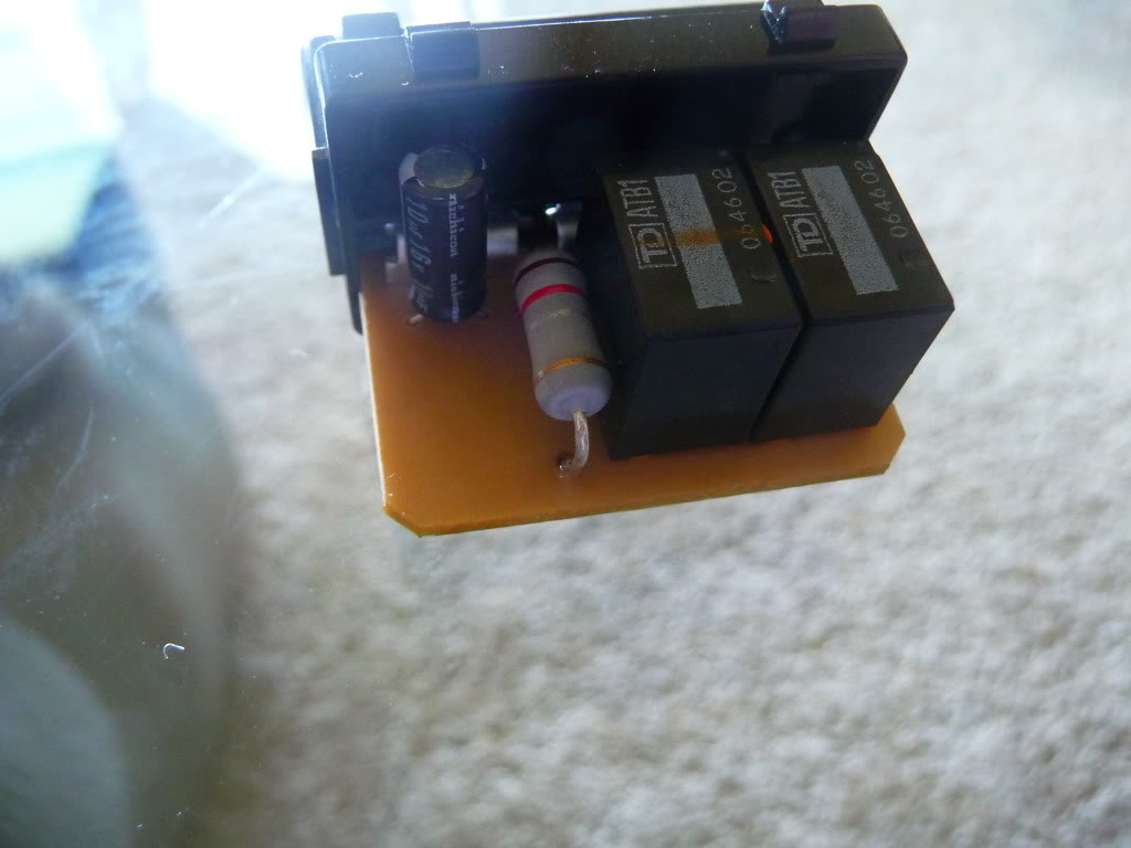
Once that is removed you will be able to see the circuit board and the "OEM Shunt Resistor". OK I didn't know shit about soldering, and when I read the first post that said "REMOVE THE SHUNT RESISTOR" I thought it was just as simple as pinching it and sliding it out. WRONG. You must DESOLDER IT to be able to remove it.
OK In this step, I'm not sure if I "Desoldered" it correctly but I did it anyways. I went to youtube.com and typed in "How to Solder" and came across these 2 informative helpful videos.
http://www.youtube.com/watch?v=I_NU2ruzyc4
http://www.youtube.com/watch?v=BLfXXRfRIzY
After watching that, I began to have a general idea on how to solder. Still don't know how to "Desolder" and I don't have a "Desoldering Gun" so forgive me If i broke any rules.
I plugged my soldering gun into the outlet and let it heat up for about 5 mins. Once it seemed up to temperature i took the gun and (i DID NOT tin the tip while removing the shunt resistor) touched the shunt resistor on the underside of the circuit board (the side where the its green and you can see the other solders on the relay). I touched the previous solder with the tapered side of my soldering gun and held it there for about 10 seconds. Once I counted to 10 seconds (Don't ask me where I got the 10 second idea from, made it up myself) I quickly, and i mean QUICKLY set the solder gun down on the stand and grabbed the pliars that came with my kit and tugged on the resistor (the side that I melted the solder) and it came out half way and stuck. I re-heated the solder on the same side again for a few seconds and was able to full pull it out with my pliars. Repeated the same step for the other side of the resistor that's still intact. TIP : When you heat up the solder to remove the shunt resistor, make sure you try to remove it quickly because if you take too long, the solder will cool down and harden again so the shunt resistor won't budge. That's why I set my gun down and quickly grabbed the pliars. I still had to re-heat the solder a few times to be able to fully extract the shunt resistor
SOLDERING YOUR 0.24 RESISTOR
With the shunt resistor finally removed, I took my 0.24ohm resistor and bent the wires and put it in place just like how the OEM shunt resistor was sitting. I noticed on the underside there was alot of extra wiring from the resistor so I took my diagonal cutters and cut it short to the length of the other wires that have been already soldered onto the turn signal relay. With the turn signal relay laying on my floor upside down (Green side of the board facing UP towards ceiling) I began to slowly solder it.
First I tinned the tip and started on one side slowly. Took my precious time because this was my first time ever soldering and I didn't want to melt anything or screw anything up. A tip that I used from the youtube videos was to never apply the solder directly to the soldering gun while you're heating up an item to be soldered... Always apply solder to the opposite side and let the heat melt the solder, and not the soldering gun itself. If you don't understand what I mean than please watch the first youtube video I linked. He makes it clear "How NOT TO solder".
Fairly simple and took no more than 5 minutes to complete soldering it. Sorry for not having any pictures.
I still have my OEM halogen bulbs for my front and rears, my front switchbacks and rear red LEDs should be here by friday so I wanted to go ahead and do this DIY ahead of time so I can just install the bulbs right away.
Needless to say, with the 0.24ohm resistor in place my regular halogen bulbs still blink just fine FRONT and BACK.
Can't wait til I get my LED's in to really test it out to see If I correctly soldered it or not..
DID NOT have a soldering gun or even held one until today.
I tried calling around to various computer shops in my area to ask if they can solder it and this is how it went.
1st place - "Oh I don't do soldering. I used to have a co-worker who did all the circuit board work, but he doesn't do it anymore"
2nd place - "Oh yes we do soldering, but we only solder computer and laptop parts, we can't solder anything outside of that due to liability purposes" (or some stupid BS)
3rd place - "No I don't do soldering, but let me try and get into contact with a friend who can possibly do it. Just call me back, leave me a voicemail saying what you need done, and I'll send the voicemail to my friend to get a price quote for you"
WTF? I did not expect for it to be such a PITA just to find a computer shop to solder this for me. Finally got fed up and looked online at radioshack for soldering guns.
Ended up purchasing http://www.radioshack.com/product/in...rodsPerPage=60.
Total was $25 after taxes.
Honestly, I didn't feel like I had enough experience or will to even attempt this myself. That's why I called other places. But after calling around and not getting anywhere for about 15 mins I just thought to myself "Fuck it, might as well learn on your own so you can do it in the future"
REMOVING THE TURN SIGNAL RELAY...
Taking out the turn signal relay was a little challenge... It's held in by a clip and there's 1 on each side (left and right) that hold it in. When I would be able to unclip one side, the other side would still be clipped in. When I would try and go to the other side to unclip it, than the opposite side that was previously unclipped would get clipped. I finally took a flat head screw driver and accidentally broke one of the clips on the right side (the clip that you can't see because it's facing towards the front of the car). I thought I was in trouble, but really all I did was make it ALOT easier to remove the turn signal relay. Trust me, I tried hard to properly pull out the turn signal relay without breaking anything, but amidst the frustration of the clips constantly snapping back in place when I would get one side out, and the 95F heat blazing on the back of my head, I decided to get a little rough with it and broke the clip lol.
REMOVING THE GREY PLASTIC HOUSING FROM THE RELAY..
Once I was able to remove the turn signal relay, I brought it inside to inspect it. On the exterior of the turn signal relay is a silver/grey-ish housing. No one explained how to remove this cover (well I skimmed the first 2-3 pages and found nothing). I took a very small flat head and jammed it in between the 2 different plastics and slowly pulled it up so it would unclip itself. This grey housing is also held in place by small clips. 2 on each side, a total of 4. First pry one side til its unclipped, than flip the turn signal relay over and do the same for the other side. Once both side is unclipped just use both hands and slowly remove the grey housing cover.
REMOVING THE OEM SHUNT RESISTOR..
Once that is removed you will be able to see the circuit board and the "OEM Shunt Resistor". OK I didn't know shit about soldering, and when I read the first post that said "REMOVE THE SHUNT RESISTOR" I thought it was just as simple as pinching it and sliding it out. WRONG. You must DESOLDER IT to be able to remove it.
OK In this step, I'm not sure if I "Desoldered" it correctly but I did it anyways. I went to youtube.com and typed in "How to Solder" and came across these 2 informative helpful videos.
http://www.youtube.com/watch?v=I_NU2ruzyc4
http://www.youtube.com/watch?v=BLfXXRfRIzY
After watching that, I began to have a general idea on how to solder. Still don't know how to "Desolder" and I don't have a "Desoldering Gun" so forgive me If i broke any rules.
I plugged my soldering gun into the outlet and let it heat up for about 5 mins. Once it seemed up to temperature i took the gun and (i DID NOT tin the tip while removing the shunt resistor) touched the shunt resistor on the underside of the circuit board (the side where the its green and you can see the other solders on the relay). I touched the previous solder with the tapered side of my soldering gun and held it there for about 10 seconds. Once I counted to 10 seconds (Don't ask me where I got the 10 second idea from, made it up myself) I quickly, and i mean QUICKLY set the solder gun down on the stand and grabbed the pliars that came with my kit and tugged on the resistor (the side that I melted the solder) and it came out half way and stuck. I re-heated the solder on the same side again for a few seconds and was able to full pull it out with my pliars. Repeated the same step for the other side of the resistor that's still intact. TIP : When you heat up the solder to remove the shunt resistor, make sure you try to remove it quickly because if you take too long, the solder will cool down and harden again so the shunt resistor won't budge. That's why I set my gun down and quickly grabbed the pliars. I still had to re-heat the solder a few times to be able to fully extract the shunt resistor
SOLDERING YOUR 0.24 RESISTOR
With the shunt resistor finally removed, I took my 0.24ohm resistor and bent the wires and put it in place just like how the OEM shunt resistor was sitting. I noticed on the underside there was alot of extra wiring from the resistor so I took my diagonal cutters and cut it short to the length of the other wires that have been already soldered onto the turn signal relay. With the turn signal relay laying on my floor upside down (Green side of the board facing UP towards ceiling) I began to slowly solder it.
First I tinned the tip and started on one side slowly. Took my precious time because this was my first time ever soldering and I didn't want to melt anything or screw anything up. A tip that I used from the youtube videos was to never apply the solder directly to the soldering gun while you're heating up an item to be soldered... Always apply solder to the opposite side and let the heat melt the solder, and not the soldering gun itself. If you don't understand what I mean than please watch the first youtube video I linked. He makes it clear "How NOT TO solder".
Fairly simple and took no more than 5 minutes to complete soldering it. Sorry for not having any pictures.
I still have my OEM halogen bulbs for my front and rears, my front switchbacks and rear red LEDs should be here by friday so I wanted to go ahead and do this DIY ahead of time so I can just install the bulbs right away.
Needless to say, with the 0.24ohm resistor in place my regular halogen bulbs still blink just fine FRONT and BACK.
Can't wait til I get my LED's in to really test it out to see If I correctly soldered it or not..
Last edited by vietxquangstah; 09-27-2011 at 07:26 PM.
The following users liked this post:
bluetroll (11-16-2016)
09-27-2011, 07:23 PM
#331
Race Director
iTrader: (8)
Thanks for the little story.
It's gonna be my first time soldering too (or I might get a friend to quickly do it; take a couple minutes right? lol).
My resistors should be here soon thanks to xavier25 and my LEDs should be here in about a month =(
It's gonna be my first time soldering too (or I might get a friend to quickly do it; take a couple minutes right? lol).
My resistors should be here soon thanks to xavier25 and my LEDs should be here in about a month =(
09-27-2011, 07:34 PM
#332
Sorry for the LEDs not arriving til next month
 . When I was looking on eBay I made sure the seller was from the US and the delivery time anywhere between 2-6 days. Sure the Hong Kong sellers may have the same LEDs for a fraction of the price, but their delivery times is 2-3 weeks! I suppose if you're not in a rush than you could save yourself a few $$ and go with the Hong Kong sellers, but in my case I wanted to get them in ASAP without having to pay extra $ for expedited shipping. Paying a few extra bucks to get my LEDs 2 weeks sooner compared to most Hong Kong sellers seemed perfect for me
Last edited by vietxquangstah; 09-27-2011 at 07:37 PM.
09-27-2011, 07:37 PM
#333
Instructor
@vietxquangstah
Sounds like you did everything perfectly (minus breaking that clip, but who cares about that). You are more than ready to install your LEDs and enjoy the lack of hyperflash. Soldering is really easy once you understand what you're doing, steady hands and sometimes an extra pair of hands help when working on stuff this small (I heated the shunt resistors solder points while my brother pulled it out). As long as you didn't accidentally de-solder something else, you should be good to go!
Now you can solder whatever you want.
Good luck to whoever else does their own soldering, don't be intimidated by it.
Also, I've received all but one set of my LEDs from Hong Kong, I don't mind waiting a little while for saving quite a bit o cabbage.
Last edited by BSpecialist; 09-27-2011 at 07:39 PM.
09-27-2011, 07:38 PM
#334
Race Director
iTrader: (8)
NP! Just trying to help other fellow members out. I'm sure alot of us don't have any soldering background so I figured if a non-experienced person can accomplish it, why not do a small write-up to help others who also don't have any experience. I tried to include as much detail as i could.
Sorry for the LEDs not arriving til next month. When I was looking on eBay I made sure the seller was from the US and the delivery time anywhere between 2-6 days. Sure the Hong Kong sellers may have the same LEDs for a fraction of the price, but their delivery times is 2-3 weeks!
Sorry for the LEDs not arriving til next month
. When I was looking on eBay I made sure the seller was from the US and the delivery time anywhere between 2-6 days. Sure the Hong Kong sellers may have the same LEDs for a fraction of the price, but their delivery times is 2-3 weeks!
09-27-2011, 07:44 PM
#335

I than resorted to using pliars
 09-27-2011, 07:53 PM
#336
Instructor
HA! I forgot to mention when I heated up the shunt resistor solder points and tried to pull it out I burnt my finger. I guess I was holding the gun at the solder point too long and the shunt resistor started to absorb the heat. I didn't realize it, and when I went to pinch the shunt resistor to pull it out I burnt my finger pretty bad.
I than resorted to using pliars
I than resorted to using pliars
09-28-2011, 03:04 PM
#338
So I got my rear red LEDs in the mail today. Installed them and they blink just fine, no hyperflash. I'm glad I purchased it in RED instead of white because when standing on the rear of the car while the turn signal is on, you can tell its red. Very red. Deep rich red color, and I love that.
I can't imagine what a WHITE LED bulb would look like. The red turn signal area would most likely look washed out due to the bright white of the LEDs and red lense doing its job filtering out all the white light.
If anyone is interested in what bulbs I bought, you can get them here - http://cgi.ebay.com/ebaymotors/ws/eB...ht_1947wt_1165 - I was fortunate enough to catch it while it was on sale and got it for $12.59/per LED bulb. You will need two (1 Left, 1 Right). I got both for $25.18 + FREE shipping.
Placed order on Sunday, Sept 25. Arrived in my mailbox Wednesday, Sept 28. From Cali ---> Texas.
The brightness of these compared to halogen bulbs is a huge difference. I swapped these out at 2PM in the afternoon so It was still plenty bright outside. I left the right side with the halogen bulb and swapped the drivers side with the LED. When I turned on my hazards to compare both, the LED was more vibrant and in-your-face-you-can't-miss-it bright. While the stock halogens looked dull and somewhat hard to see when compared to the LED in broad daylight.
It definitely looks brighter than halogen side by side. If it looks this bright at 2PM I can't imagine how bright it will look at night after the sun starts to set!
09-28-2011, 05:55 PM
#339
I was thinking.... since you can do this to prevent hyperflash for front and rear led turn signals, I noticed when installing LED DRLs (sorry, i know this is a diff subject) you have to also install a load resistor (like ijdmtoy, v-leds, etc).
Is there such thing as a 'DRL relay module' that is in the fuse box somewhere that we can perhaps pull out, simply solder in a new resistor (much like we did for our front/rear led signals), and plug it back in and still be able to use OEM stock halogen, and whenever we decide to upgrade to LEDs we can just swap the DRLs and still not have to worry about load resistor? and possibly prevent DRL light on the dashboard from appearing too because due to the resistor being in place, the computer believes the LED is getting the correct amount as a halogen ?
just a thought. i noticed no one ever mentioned it so i thought i'd just throw it out there
The following users liked this post:
gilla_monster (06-13-2013)
09-28-2011, 08:39 PM
#341
Race Director
iTrader: (8)
Thanks for the vid!
It would have been nicer if you could record both the tail lights at the same time so we can see side by side comparison.
It would have been nicer if you could record both the tail lights at the same time so we can see side by side comparison.
10-05-2011, 09:53 AM
#342
Instructor
If I'm only using 2 load resistors for my headlights, is there a cause for concern? I know some people are using 4 load resistors (headlights and tail lights) and could see why people would want to switch to this method as it seems safer for the car.
10-06-2011, 12:40 PM
#343
I prefer the 4 ohm 100W load resistor (going with the load resistor option) as the calculations have been done on a different thread that shows this resistor coming much closer to the stock resistance (so using less power and generated less heat) than using two 3 ohm 60W resistors per side.
On a side note I originally bought the .12 ohm resistors. Once I have time I plan on doing this to my car (running 2 in parallel). I'll have enough resistors left over to do 4 more setups so if anyone want's them just let me know. I can even solder them into parallel so all you have to do is solder them on the board. If you are in KC area I can do that for you as well.
The following users liked this post:
R.L. ina TL (10-06-2011)
10-06-2011, 07:24 PM
#344
Instructor
Yea I scratched doing the load resistors and I'm too going with the .12 ohm way. I don't want to deal with buying two then another two down the line for the tails. Also adding the .12 resistor looks ridiculously easy.
10-08-2011, 09:13 PM
#345
Instructor
You will want to do the .24ohm resistor if you plan on doing all 4 corners with LEDs. Even if you are only doing the front now and want the option to adding rears later I would still suggest a .24ohm resistor.
The following users liked this post:
emilio320 (10-10-2011)
10-08-2011, 09:33 PM
#346
Race Director
iTrader: (8)
Just waiting for my front LEDs to come in then I'll solder my .24 ohms in.
 10-10-2011, 01:29 PM
#349
Race Director
iTrader: (8)
Yes
10-10-2011, 02:54 PM
#351
Race Director
iTrader: (8)
10-10-2011, 03:14 PM
#352
i watched 2 youtube soldering videos and i felt that i could tackle it myself.
i tried it out, and sure enough it worked. just be very very careful and don't rush. pay close attention to what you're doing and be aware of potential mistakes like accidentally touching a nearby solder point with the gun that you're not supposed to.
i tried it out, and sure enough it worked. just be very very careful and don't rush. pay close attention to what you're doing and be aware of potential mistakes like accidentally touching a nearby solder point with the gun that you're not supposed to.
10-10-2011, 11:04 PM
#354
I appreciate the advice guys!! I'm not bad at soldering, I just don't trust myself with my car. I've soldered all kinds of stuff for my Xbox.
But just in case, the part number would be great
But just in case, the part number would be great
10-10-2011, 11:09 PM
#355
Race Director
iTrader: (8)
The following users liked this post:
Undying Dreams (09-07-2012)
 10-12-2011, 01:23 AM
#359
Intermediate

On a side note I originally bought the .12 ohm resistors. Once I have time I plan on doing this to my car (running 2 in parallel). I'll have enough resistors left over to do 4 more setups so if anyone want's them just let me know. I can even solder them into parallel so all you have to do is solder them on the board. If you are in KC area I can do that for you as well.