Small cameras on side-view mirrors
 11-24-2012, 10:01 PM
#81
Freakin' turn signal voltages are messing this entire plan up!
So I hooked up the multimeter to the ORG/WHT and BLK turn signal wires again, and without the turn signals turned on, the DC voltage was at 0.5V. With the turn signal turned on, it dropped to 0.2V.
So I hooked up the multimeter to the ORG/WHT and BLK turn signal wires again, and without the turn signals turned on, the DC voltage was at 0.5V. With the turn signal turned on, it dropped to 0.2V.
 11-24-2012, 10:57 PM
#82
Sounds like it behaves like a steering control wire. A resistance is applied when you engage the switch which causes a change in voltage that then signals the BCM to turn on the signal.
I don't know how elaborate you want to get here, but this is how I would tackle it:
1) Run the power wires and the video cable for both cameras in the car through the door molex by drilling or filing out the blank pin locations. You may have to cut and splice the video output in order to fit it through the plug since you won't be able to fit an RCA.
2) Power both cameras off of an acc power source so they are on with the key.
3) Use a PAC-TR7PRO
http://pac-audio.com/productDetails....&CategoryID=31
and use the actual turn signal pulse from the bulb (or wherever you can grab it, probably even in the mirror from the front mounted bulb) as 2 different inputs (left and right) for the TR7PRO. Program the TR7PRO to timed outputs for whatever duration you want to leave the image on the screen. Program the inputs as (-) "pulse", program the outputs as "timed" one (+) one (-).
4) Use the outputs of the TR7PRO to trigger your video input device. The VCIHON1 I sent you the PM about would allow this to work. Use one output as the the (+) trigger to the "reverse camera/video 2" input on the VCIHON1 This one will . Use the other output of the TR7PRO to trigger the (-) "Video 1" input on the VCIHON1. The trigger that trips the "video 1" input will act like the switch by providing a ground so video 1 is displayed. The trigger that comes off of the TR7PRO for the 2nd camera, running on the "r-cam/video2" input can be programmed as a positive to behave like a back-up camera, displaying that particular camera image on the screen.
The drawback to this is that if you turn on your signal that image will be displayed until the TR7PRO times out which may be longer or shorter than you want it on that particular instance. If you can live with that, you are golden.
And if you want to go really nuts, you could program the other 2 outputs to trip 2 relays to interrupt the turn signal inputs going to the TR7PRO after the first pulse so it does not continue to pulse the input each time the bulb clicks on. At that point though, you are really just showing off

edit: you may even be able to time the inputs and outputs correctly to "cycle" the inputs of the VCIHON1 to display the image uninterrupted until the turn signal is turned off. That would be tricky though.
Last edited by DiamondJoeQuimby; 11-24-2012 at 11:07 PM.
11-25-2012, 01:25 AM
#83

heres the link to the manual...
22-98 pretty much says it data... the way I take it. PDFs in windows 8 sucks a$$ so I haven't went through it in any great detail so there may be an easier way.
I don't think you should attempt to flip that relay with a data signal. I would be thinking more along the lines of modifying the voltage going to the bulb to be constant for a trigger. The type of circuit is right on my tongue. Maybe just a large cap could do the job. Anyways if you do use a manual switch the mod loses all the "coolness" and practicality.
When I ran my speaker wire through the door I just drilled a whole right below the rubber grommet, cut a slit in the grommet and fed the wire threw and I did find out there is such a thing as wire lube that day and it makes all the difference in the world.
11-25-2012, 01:31 PM
#84
Sounds like it behaves like a steering control wire. A resistance is applied when you engage the switch which causes a change in voltage that then signals the BCM to turn on the signal.
I don't know how elaborate you want to get here, but this is how I would tackle it:
1) Run the power wires and the video cable for both cameras in the car through the door molex by drilling or filing out the blank pin locations. You may have to cut and splice the video output in order to fit it through the plug since you won't be able to fit an RCA.
2) Power both cameras off of an acc power source so they are on with the key.
3) Use a PAC-TR7PRO
http://pac-audio.com/productDetails....&CategoryID=31
and use the actual turn signal pulse from the bulb (or wherever you can grab it, probably even in the mirror from the front mounted bulb) as 2 different inputs (left and right) for the TR7PRO. Program the TR7PRO to timed outputs for whatever duration you want to leave the image on the screen. Program the inputs as (-) "pulse", program the outputs as "timed" one (+) one (-).
4) Use the outputs of the TR7PRO to trigger your video input device. The VCIHON1 I sent you the PM about would allow this to work. Use one output as the the (+) trigger to the "reverse camera/video 2" input on the VCIHON1 This one will . Use the other output of the TR7PRO to trigger the (-) "Video 1" input on the VCIHON1. The trigger that trips the "video 1" input will act like the switch by providing a ground so video 1 is displayed. The trigger that comes off of the TR7PRO for the 2nd camera, running on the "r-cam/video2" input can be programmed as a positive to behave like a back-up camera, displaying that particular camera image on the screen.
The drawback to this is that if you turn on your signal that image will be displayed until the TR7PRO times out which may be longer or shorter than you want it on that particular instance. If you can live with that, you are golden.
And if you want to go really nuts, you could program the other 2 outputs to trip 2 relays to interrupt the turn signal inputs going to the TR7PRO after the first pulse so it does not continue to pulse the input each time the bulb clicks on. At that point though, you are really just showing off
edit: you may even be able to time the inputs and outputs correctly to "cycle" the inputs of the VCIHON1 to display the image uninterrupted until the turn signal is turned off. That would be tricky though.
 11-25-2012, 01:48 PM
#85
I routed the video wire under the plastic pieces on either side of the car, and when I get some more time, I'll route the wires to the trunk in anticipation of getting the NAVtool unit.
The other thought that I had was that the blue wire from the NAVtool unit requires a 12V input. I cannot hook that up to the ORG/WHT turn signal wire because the voltage is too low.
This is getting a little frustrating now.
The other thought that I had was that the blue wire from the NAVtool unit requires a 12V input. I cannot hook that up to the ORG/WHT turn signal wire because the voltage is too low.
This is getting a little frustrating now.
11-25-2012, 04:50 PM
#86
I have two options at this point: try to figure out the electrical voltage thing or hook up the blue wire to the ACC socket (so the NAVtool unit would be on all the time). I would have to hook up a normally open (i.e. off) push button switch on each of the camera power wires to work that respective camera. My initial thought would be to open a small hole for the push button switches in the steering wheel switches, but taking off the steering wheel plastic is a bit daunting, especially since it requires a torx (I think) bit.
11-25-2012, 11:39 PM
#89
22-199 on the manual has your answer.
Here's what I'm getting... 6 is always hot... and 2 and 3 provide a ground to activate coil. 4 and 5 and going to the bulb I believe and will fluctuate resulting in the ~10v the manual says is read.
If so unbolt fuse/relay panel T tap 2 and 3 respectively to your camera power and trigger wire.
Here's what I'm getting... 6 is always hot... and 2 and 3 provide a ground to activate coil. 4 and 5 and going to the bulb I believe and will fluctuate resulting in the ~10v the manual says is read.
If so unbolt fuse/relay panel T tap 2 and 3 respectively to your camera power and trigger wire.
11-26-2012, 05:18 AM
#90
Bought the NAVtool unit.
Question. The blue wire to the NAVtool unit is a trigger mechanism to turn it on automatically, correct? If I connect that to a constant +12V source, like the ACC cigarette lighter wires, it will be on automatically and all the time, right?
Reason I'm asking is that if I cannot figure this out, I'm going to add two push button switches to the power wires of the cameras, and be able to turn then on with push buttons (from the steering wheel).
11-26-2012, 05:21 AM
#91
22-199 on the manual has your answer.
Here's what I'm getting... 6 is always hot... and 2 and 3 provide a ground to activate coil. 4 and 5 and going to the bulb I believe and will fluctuate resulting in the ~10v the manual says is read.
If so unbolt fuse/relay panel T tap 2 and 3 respectively to your camera power and trigger wire.
Here's what I'm getting... 6 is always hot... and 2 and 3 provide a ground to activate coil. 4 and 5 and going to the bulb I believe and will fluctuate resulting in the ~10v the manual says is read.
If so unbolt fuse/relay panel T tap 2 and 3 respectively to your camera power and trigger wire.
Edit: Nevermind. It's downloading.
Double edit: Holy crap. Talk about the goldmine of the repair manual! Awesome! Thanks bro. I'm looking at this now and trying to understand what the hell you said.
Last edited by gatrhumpy; 11-26-2012 at 05:35 AM.
11-26-2012, 05:43 AM
#92
22-199 on the manual has your answer.
Here's what I'm getting... 6 is always hot... and 2 and 3 provide a ground to activate coil. 4 and 5 and going to the bulb I believe and will fluctuate resulting in the ~10v the manual says is read.
If so unbolt fuse/relay panel T tap 2 and 3 respectively to your camera power and trigger wire.
Here's what I'm getting... 6 is always hot... and 2 and 3 provide a ground to activate coil. 4 and 5 and going to the bulb I believe and will fluctuate resulting in the ~10v the manual says is read.
If so unbolt fuse/relay panel T tap 2 and 3 respectively to your camera power and trigger wire.

The other question is how do I hook up the wires to the relay if it's bolted in there?
Last edited by gatrhumpy; 11-26-2012 at 05:52 AM.

 11-26-2012, 08:17 AM
#95
Just spoke with an electrical engineer, and we may have figured this out using a relay and another microcontroller.
Apparently looking at the electrical diagram I made, I put the black probe on the wrong black wire (the wire going from the Combination Switch Control Unit to the Turn Signal Light Switch). I have to find another ground wire to put the black probe of the multimeter on, while the red probe goes on the ORG/WHT wire and the BLK/GRN wire (separately).
Apparently looking at the electrical diagram I made, I put the black probe on the wrong black wire (the wire going from the Combination Switch Control Unit to the Turn Signal Light Switch). I have to find another ground wire to put the black probe of the multimeter on, while the red probe goes on the ORG/WHT wire and the BLK/GRN wire (separately).
11-26-2012, 12:04 PM
#96
The blue + trigger wire is exactly that. It triggers the unit to display the image. You would normally connect this to a 12v reverse wire. The regular power and ground connections still need to be made. If you connect the trigger wire to a constant, the camera image will be on all the time. You would have to break that connection to return to the NAV display.
11-26-2012, 12:15 PM
#97
The blue + trigger wire is exactly that. It triggers the unit to display the image. You would normally connect this to a 12v reverse wire. The regular power and ground connections still need to be made. If you connect the trigger wire to a constant, the camera image will be on all the time. You would have to break that connection to return to the NAV display.
I have designed a circuit depending on what the voltage reading is across the ORG/WHT wire and the black ground wire.
11-26-2012, 01:32 PM
#98
OR I could have a push button switch connect in line with the blue wire (which would be connected to the RED/WHT cigarette lighter adapter wires), that, when I push it momentarily closed, it would show me the camera based on a three way toggle switch (whether the toggle switch is center, left, or right). That's the way the new Accord has it becauses being connected to the turn signal.

Last edited by gatrhumpy; 11-26-2012 at 01:45 PM.
11-26-2012, 05:37 PM
#100
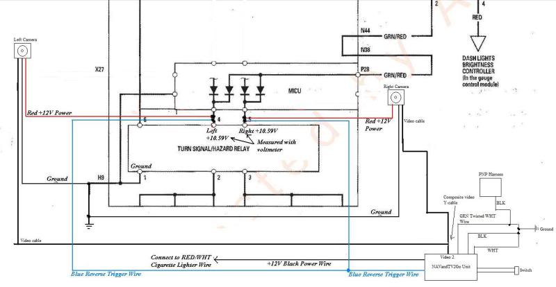
So I took out the turn signal relay under the dash and tested pins 4 (left positive) with pin 1 (ground). It measured 10.59V, and the multimeter stayed a consistent 10.59V. It's pretty close to the +/- 10% needed for the 12V of the camera, so I'm going to put the plus camera wire on pin 4 and the negative on pin 1 without the relay in and connect the video wire to a TV to see if the camera powers on when the turn signal is activated. If it is, my next problem will be how to tap into pins 4 and 1 WITH the relay in. But at least the video camera will work!
Stay tuned!
Stay tuned!
11-26-2012, 07:04 PM
#101
It works! It works!
Holy crap! It works!
I took out the turn signal relay, connected the camera positive wire to pin 5 and the camera negative wire to pin 1, turned on the car and turn signal, and connected the camera to a small TV, and it works!
Now I have to see if the 10.59V at those pins is enough voltage to turn on the NAVTool unit via the blue wire. We'll see...
 11-27-2012, 07:53 PM
#106
I routed the right camera power wire to the left side just now. Took about 15 minutes because I wanted to zip-tie the wires.
I get the NAVtool box (thanks Mugen-K!) on Thursday, and in anticipation of getting it, I'm going to take out the right-side trunk lining and the rear seat tomorrow afternoon to route the wires that I need to the front (switch and the blue trigger wire).
The hardest part left is trying to tap into the relay box somehow. I'm modifying some spade connectors to tap into the hazard/turn signal relay. I'll let everyone know how it goes!
 11-28-2012, 06:58 AM
#108
Suzuka Master
how about just steal a 2013 Honda Accord EX-L mirror and call it a day  . I can't wait to see the outcome.
. I can't wait to see the outcome.
11-28-2012, 04:27 PM
#112
I ran into some of the same issues when I tried to use my factory camera with an aftermarket radio. Couldn't get it to turn on b/c the power for it is controlled through the BCM. Ended up just punting and using an aftermarket Alpine camera in the same mount.
11-28-2012, 09:13 PM
#113
So I spent about three hours removing the rear seat upper portion and lower portion, routing the two video wires the rest of the way to the trunk, and routing the NAVtool blue wire connection and the cigarette lighter connection to the trunk in anticipation of getting the NAVtool unit tomorrow. I also removed part of the trunk lining. The only thing I have to do it to make the necessary electrical connections for the NAVtool unit and I get to see how this sucker works tomorrow!
I also modified several spade connectors to fit into the old turn signal relay socket. I had to splice three of the six pins of the turn signal relay: pin 1 for ground, pin 4 for the left +12V of the left camera, and pin 5 for the right +12V of the right camera. I took a picture of what I did, but will post it tomorrow when and if this works.
I plugged in the relay again to the spliced connections, and the relay works.
 11-29-2012, 09:15 PM
#117
I'll be posting pics soon, and several videos shortly.
The hardest parts of this project was modifying the spade connectors (not really hard per se, but time-consuming) to fit the turn signal relay, and putting the damn seat back back in the car.
The hardest parts of this project was modifying the spade connectors (not really hard per se, but time-consuming) to fit the turn signal relay, and putting the damn seat back back in the car.
11-29-2012, 09:32 PM
#118
Money shot:
Picture of the modified relay:

Pin 1 at the top is the ground, pin 4 is for the left hand positive camera +12V wire and pin 5 is for the right hand positive camera +12V wire. The blue wire needs to be spliced into pins 4 and 5 for this to work.
Picture of the modified relay:
Pin 1 at the top is the ground, pin 4 is for the left hand positive camera +12V wire and pin 5 is for the right hand positive camera +12V wire. The blue wire needs to be spliced into pins 4 and 5 for this to work.
