Small cameras on side-view mirrors
 11-15-2012, 12:39 AM
#41

1 trigger = 1 switched input = 1 camera
Hopefully you're an electrical engineer and you can explain to me exactly how you plan to get two automatically switched inputs with anything less than 2 NO SPDT relays and that running power and signal on a single relay... I'm sure there won't be any noise in the video feed. But you've probably thought this through way more than I have, so please school me.
Hopefully you're an electrical engineer and you can explain to me exactly how you plan to get two automatically switched inputs with anything less than 2 NO SPDT relays and that running power and signal on a single relay... I'm sure there won't be any noise in the video feed. But you've probably thought this through way more than I have, so please school me.
 11-15-2012, 05:36 AM
#42
Mechanical engineer, but I have a strong electrical background in my hobbies.
Yes, the NAVandTV2GO unit and NAVtool units have one switched power input for a reverse camera. Those two power wires could be connected to any power sources (even multiple sources) as long as BOTH are not on at the same time and all are in parallel.
So normally when the rear-view camera is connected to the brake lights and you put the car in reverse, it triggers the reverse lights to come on, which then routes the power through the DVD converter unit to turn on the camera.
Same thing with the turn signals. If only one comes on at any one time, it will turn on that particular camera only. I could have several cameras attached to the reverse camera output of the NAVtool unit if I wanted to, as long as no two cameras are on at the same time.
I will also have a coaxial Y cable that connects from both cameras to the automatically switched video output from the NAVtool unit.
This is how this would work:
Say I'm driving down the road, and I turn on my right turn signal (the left camera and video signal are off). That sends an electrical power signal to turn on the right camera under the right side mirror. Once the power is on to the camera, it would send a video signal through the Y-cable to the NAVtool unit, through the DVD Navi drive, and then to the navi screen up front.
Does that make sense?
Last edited by gatrhumpy; 11-15-2012 at 05:39 AM.
11-15-2012, 11:00 AM
#43
F'in Y cable... I was going off my premise of having both cams powered at the same time but if not you have a pretty good idea. Except the Hazard lights which hopefully you never use.
Looks like only place to take power suitable place is before the combo switch control unit...
Black and white 12pin connector (the lower one) underneath the steering column cover
Pin 4 for left (black/light green wire) and pin 10 for right (orange/white)
Above info is from an 04-06 ETM but is most likely to be correct.
You should def do this though. Relatively cheap easy and functional. I might have to put this on my wish list.
The following users liked this post:
gatrhumpy (11-15-2012)
11-15-2012, 01:04 PM
#44
F'in Y cable... I was going off my premise of having both cams powered at the same time but if not you have a pretty good idea. Except the Hazard lights which hopefully you never use.
Looks like only place to take power suitable place is before the combo switch control unit...
Black and white 12pin connector (the lower one) underneath the steering column cover
Pin 4 for left (black/light green wire) and pin 10 for right (orange/white)
Above info is from an 04-06 ETM but is most likely to be correct.
You should def do this though. Relatively cheap easy and functional. I might have to put this on my wish list.
Looks like only place to take power suitable place is before the combo switch control unit...
Black and white 12pin connector (the lower one) underneath the steering column cover
Pin 4 for left (black/light green wire) and pin 10 for right (orange/white)
Above info is from an 04-06 ETM but is most likely to be correct.
You should def do this though. Relatively cheap easy and functional. I might have to put this on my wish list.
Yeah, I probably will end up doing this mod IF I can find a freakin' NAVtool unit for less than $200!
 11-15-2012, 01:08 PM
#45
BANNED
iTrader: (33)

^i saw your WTB ad in the BM. they pop up from time to time, but seem to be more scarce by the day. i snagged mine for $170 last year.
best bet might be to purchase one new from dom himself if you can't find one used.
best bet might be to purchase one new from dom himself if you can't find one used.
11-15-2012, 02:54 PM
#47
Suzuka Master
So........... the camera display is going to be using the display in the center stack? No one is going to use that when making lane changes. you need to remove the mirrors and use video displays instead of mirrors. No way in hell am I going to merge left or right and pull my vision back to the center stack. thats just silly.
11-15-2012, 05:44 PM
#48
So........... the camera display is going to be using the display in the center stack? No one is going to use that when making lane changes. you need to remove the mirrors and use video displays instead of mirrors. No way in hell am I going to merge left or right and pull my vision back to the center stack. thats just silly.
11-15-2012, 06:21 PM
#49
Suzuka Master
11-15-2012, 06:31 PM
#50
You'd be the only one who thinks that. The display in the center stack is where it's at.

For me, it's easier to add cameras under the side-view mirrors rather than replace them with expensive video monitors.
Last edited by gatrhumpy; 11-15-2012 at 06:33 PM.
11-15-2012, 09:38 PM
#51
+1 on the center stack.
Think of all the technical challenges.. especially for someone adding the post factory.
Autodimming... weatherproofing... temperature extremes... glare.
Speaking of that Gatr... don't forget to take automatic carwashes into consideration if you use them. I could just see it ripping a camera off if not mount very securely
11-15-2012, 10:21 PM
#52
http://www.tvandnav2go.com/acura_hon...ifications.php
Idk for sure wrong year ETM but if the DVD drive switches to the backup feed via 12v trigger or signal sensing you could throw 2 relays in between backup cam and the dvd drive and have them energize via turn signal switch and send the correct feed to the screen.
A little more work but a lot less money. Probably less than $30 shipped from digikey.
I got a hell of a deal on a vga to rgbs converter on ebay awhile back but no composite input, you could google around just remember the screen is 15khz.
11-16-2012, 07:17 AM
#53
+1 on the center stack.
Think of all the technical challenges.. especially for someone adding the post factory.
Autodimming... weatherproofing... temperature extremes... glare.
Speaking of that Gatr... don't forget to take automatic carwashes into consideration if you use them. I could just see it ripping a camera off if not mount very securely
Think of all the technical challenges.. especially for someone adding the post factory.
Autodimming... weatherproofing... temperature extremes... glare.
Speaking of that Gatr... don't forget to take automatic carwashes into consideration if you use them. I could just see it ripping a camera off if not mount very securely
 Just bought two cameras!
11-16-2012, 08:25 PM
Just bought two cameras!
11-16-2012, 08:25 PM
#56
The cameras from the third link, the sliver-coated ones.
Found out that the camera I bought has a mounting screw on the bottom with the video and power wires going through the center of it. I will have to drill a hole in the bottom of the side mirrors to mount these. I was hoping to use double sided tape so I would not have to drill.
Found out that the camera I bought has a mounting screw on the bottom with the video and power wires going through the center of it. I will have to drill a hole in the bottom of the side mirrors to mount these. I was hoping to use double sided tape so I would not have to drill.
 )
11-19-2012, 01:01 AM
)
11-19-2012, 01:01 AM
#59
I found this...
Would be helpful for anyone that doesn't have oem back up camera being switched through the nav. (04-06's)
Can't wait to see how this turns out
Would be helpful for anyone that doesn't have oem back up camera being switched through the nav. (04-06's)
Can't wait to see how this turns out
Last edited by juniorbean; 11-29-2012 at 08:36 AM. Reason: Deleted reference to removed diagram
11-19-2012, 05:16 AM
#60
I found this... http://www.amazon.com/4-Channel-Auto...video+switcher
Would be helpful for anyone that doesn't have oem back up camera being switched through the nav. (04-06's)
Can't wait to see how this turns out
Would be helpful for anyone that doesn't have oem back up camera being switched through the nav. (04-06's)
Can't wait to see how this turns out
My cameras should be arriving this week, so Friday I plan on removing the door panels, removing the side-view mirrors, and installing the cameras. We'll see how it goes.
11-22-2012, 09:59 PM
#62
I hope to get my cameras today. Once I get the power wires hooked up to the turn signal wires (and I have no idea what's under the plastic pieces covering the steering wheel cover), I'll try to get a video source and video monitor hooked up to verify this would work.
11-23-2012, 03:46 PM
#64
So I spliced into the GRN/BLK wire, ORG/WHT wire, and the BLK ground from the turn signals in the steering wheel cover. The connector you want is the connector that has the green tape over it.
I did that and verified that the voltage does not fluctuate at those places.
There is only one problem that I see.
I measured the voltage using the DC portion of a voltmeter, set it to 20V, and measured. The measured voltage was only 0.2V, which is not enough to run and turn on the video cameras.
I'll hook up the cameras (once I get them - hopefully today) and verify this, but I have a hunch. Might have to look at alternative methods of getting the 12V necessary to turn on the cameras.
11-23-2012, 10:54 PM
#65
It may be a PMW (I think you can measure it in AC but I new to how the bus' talk.. getting there though) ... I seen a whole service manual in PDF in one the the carpc threads it should shed some light on it. Ill post a link if I can find it again.
11-24-2012, 02:54 AM
#67
Gat, you my friend are awesome. This will be very cool if it works out.
I want to see it!
Did you decide on Navtool or the DOM's unit? I may be selling my navtool in the near future.
getting 12v should be possible from many different places. i know nothing about electronics but I spliced into one of the power seat fuses using an add-a-fuse attachment. its right there on the driver's side and probably easier. I suppose you'd have to use some sort of relay to get the turn signal constant wire to act as a trigger to actually activate the camera. hope that makes sense...sounds too obvious to be true though.
Goodluck!
Last edited by quanaman; 11-24-2012 at 02:56 AM.
11-24-2012, 06:50 AM
#68
I can let you know. I still haven't bought one yet because I'm not entirely sure this will work yet. Once I get confirmation, I'll get a NAVtool or some other box.
I'm disappointed that those wires only gave me 0.2V and not 12V. I asked an electrical engineer if he could help me build an op amp or other electrical amplifier for this project.
I did not get the cameras yesterday like the tracking website said I would (thanks UPS).
I'm disappointed that those wires only gave me 0.2V and not 12V. I asked an electrical engineer if he could help me build an op amp or other electrical amplifier for this project.
I did not get the cameras yesterday like the tracking website said I would (thanks UPS).
11-24-2012, 08:22 AM
#69
This what I did to my because all the light are control by the can bus using network messages that are from 0.1 to 5 volt. Get a small relay they have it from 0.1 volt to what ever. Use the small relay to be turned on by the turn signal and then the small relay will turn on a 12 volt relay to your camera.
11-24-2012, 09:42 AM
#71
I wonder what kind of relay(s) I should get. I think I might need two DPDT relays.
http://www.radioshack.com/product/in...rodsPerPage=60
http://www.radioshack.com/product/in...rodsPerPage=60
11-24-2012, 02:42 PM
#73
http://www.radioshack.com/product/in...ductId=2062478
That is one for 5vdc, but you can get smaller ones.
11-24-2012, 03:57 PM
#74
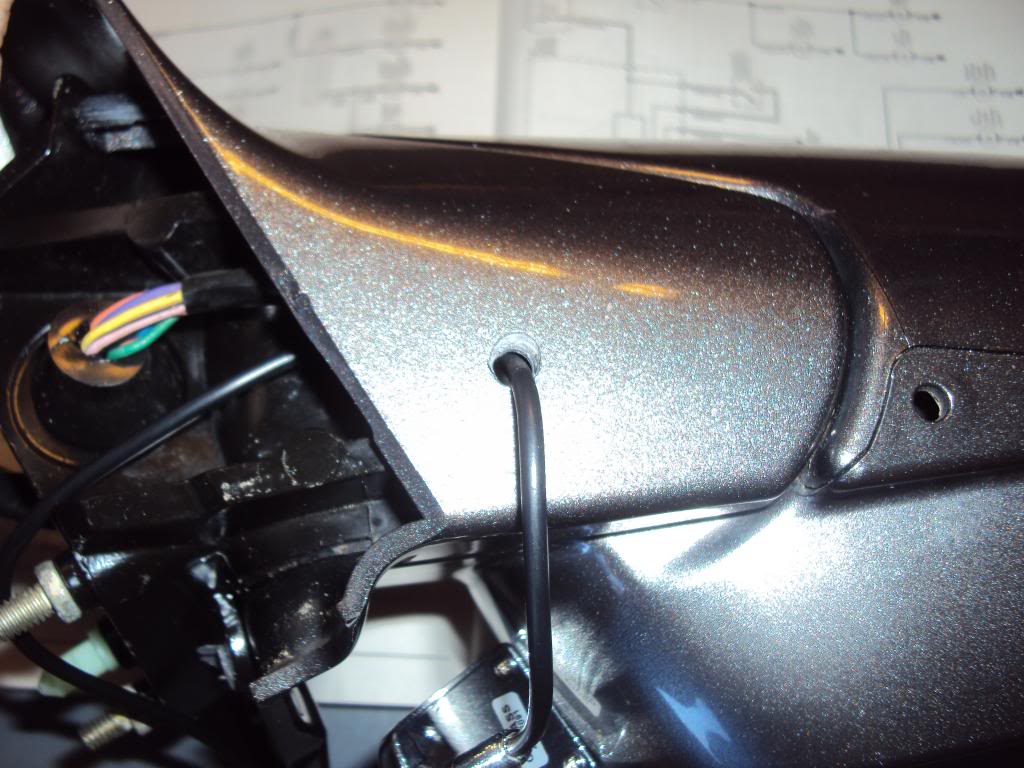
So I installed the camera, but have not hooked it up yet.
I drilled a hole in the underside of the side-view mirror and tried to route the wire inside the door. Did not work because the electrical connectors are perfect connectors from the inside of the door to the outside. There is no space to route a wire. So the camera wire is routed on the outside of the door, and I tried for an hour to route it to the cabin. Problem with THAT is that there is a double piece of metal that I cannot get the wire past, nor can I fit my hands inside there to route the wire to the cabin.
The project is a go, but now I just have to figure out how to amplify the voltage of the turn signals from 0.2V to 12V necessary for the camera power. If I can't do that, I'll just hook both cameras up to a double pole double throw switch, with neutral being off in the center position.
11-24-2012, 04:06 PM
#75
So I installed the camera, but have not hooked it up yet.
I drilled a hole in the underside of the side-view mirror and tried to route the wire inside the door. Did not work because the electrical connectors are perfect connectors from the inside of the door to the outside. There is no space to route a wire. So the camera wire is routed on the outside of the door, and I tried for an hour to route it to the cabin. Problem with THAT is that there is a double piece of metal that I cannot get the wire past, nor can I fit my hands inside there to route the wire to the cabin.
The project is a go, but now I just have to figure out how to amplify the voltage of the turn signals from 0.2V to 12V necessary for the camera power. If I can't do that, I'll just hook both cameras up to a double pole double throw switch, with neutral being off in the center position.
I drilled a hole in the underside of the side-view mirror and tried to route the wire inside the door. Did not work because the electrical connectors are perfect connectors from the inside of the door to the outside. There is no space to route a wire. So the camera wire is routed on the outside of the door, and I tried for an hour to route it to the cabin. Problem with THAT is that there is a double piece of metal that I cannot get the wire past, nor can I fit my hands inside there to route the wire to the cabin.
The project is a go, but now I just have to figure out how to amplify the voltage of the turn signals from 0.2V to 12V necessary for the camera power. If I can't do that, I'll just hook both cameras up to a double pole double throw switch, with neutral being off in the center position.
Use the reed relays I listed above to trigger the inputs of a video interface or trigger standard relays to then trigger the video interface.
Side note, personally I would power the cameras off accessory and not off the turn signal trigger. Most cameras have a slight delay from when they turn on to when they output an image. While a second or 2 doesn't seem like a long time, it will when you are traveling at 70 mph. By leaving the cameras on acc, it will pretty much be an instant display as soon as the video interface switches over.
11-24-2012, 04:15 PM
#76
You can drill out unused pin locations in the molex plugs that run through the doors. I ran 3 pair of 18 ga speaker wire through mine.
Use the reed relays I listed above to trigger the inputs of a video interface or trigger standard relays to then trigger the video interface.
Side note, personally I would power the cameras off accessory and not off the turn signal trigger. Most cameras have a slight delay from when they turn on to when they output an image. While a second or 2 doesn't seem like a long time, it will when you are traveling at 70 mph. By leaving the cameras on acc, it will pretty much be an instant display as soon as the video interface switches over.
As far as the molex connectors go, once I take out the electrical plugs from the outside and the inside of the door, I then guess you can take out the connector? The real problem is routing the wire from the outside to the inside of the cabin. I can't do that.
Edit: I cannot find relays that can be activated by 0.2V.
Last edited by gatrhumpy; 11-24-2012 at 04:22 PM.
11-24-2012, 06:15 PM
#78
In the diagram above, I hooked up the multimeter to the black and ORG/WHT wires and that's the voltage that I got.
The other thing that occurred to me is that the video switcher would not work either automatically because the blue wire needs 12V to switch automatically. That's not going to happen, so it's looking more and more like I will have to add manual switches. I have a number of push-button switches that I'll most likely attach to the steering wheel, maybe by the paddle-shifters.
Last edited by gatrhumpy; 11-24-2012 at 06:19 PM.