
Mood lighting DIY... need help.

Thread Starter
Instructor
Joined: Oct 2012
Posts: 123
Likes: 11
From: Twentynine Palms, CA / Santa Barbara, CA
Mood lighting DIY... need help.
Okay, I'll try to keep this as clear as possible. My skills with wiring and switches are very elementary. I dug around and I think I have honed in on the power leads to the dome map lights. Now, I want to create a toggle switch that will allow me to switch between the stock white lights, and the red lights I am going to install into my dome fixture. I drew up a diagram in paint to make it easier to understand(hopefully it doesn't do the opposite). Basically my question is, what would be the best way to go about doing this? Which type of switch do I need to buy, and will I need any in line fuses? I will be using T10 type sockets that accept 168 bulbs(
)
Thanks in advance, please be gentle, I'm a wiring noob.

Thanks in advance, please be gentle, I'm a wiring noob.

Engineer in Training
Joined: Mar 2012
Posts: 599
Likes: 127
From: Long Island, NY
You need a single pole double throw switch. The middle pin or lead will be common so that's the one you tie to ground. Then of the two remaining leads one will go to one set of lights and the other to your other set of lights. I recommend using a relay triggered off the switch so the switch is not handling too much of a current load. The positive of both lights would be powered off of whatever you want (parking/daytime running/etc).
Thread Starter
Instructor
Joined: Oct 2012
Posts: 123
Likes: 11
From: Twentynine Palms, CA / Santa Barbara, CA
Also, thank you. Much appreciated.
Thread Starter
Instructor
Joined: Oct 2012
Posts: 123
Likes: 11
From: Twentynine Palms, CA / Santa Barbara, CA
Are you sure I don't need a double pole double throw? My intention is to switch between one set of lights or the other, not have one set on -or- both on.
Edit: nevermind I'm trippin.
Edit: nevermind I'm trippin.
Thread Starter
Instructor
Joined: Oct 2012
Posts: 123
Likes: 11
From: Twentynine Palms, CA / Santa Barbara, CA
Like this, yes?

Obviously the actual wiring strategy for the additional T10 sockets to abridged, this is just very basic to confirm what I think you're telling me. Visual learner :P
Here is the diagram I'm going off of...


Obviously the actual wiring strategy for the additional T10 sockets to abridged, this is just very basic to confirm what I think you're telling me. Visual learner :P
Here is the diagram I'm going off of...

Last edited by WestCoastin31; Aug 8, 2013 at 07:29 PM.
Engineer in Training
Joined: Mar 2012
Posts: 599
Likes: 127
From: Long Island, NY
I just got home from a very long day at work and schematics is the last thing I want to look at lol. I'll draw something for you real quick tomorrow morning and upload it here, but in short, no. The way you have the switch wired up would cause the power leads to short directly to ground.
Dallas Chapter Leader (Midwest Region)
Joined: Feb 2013
Posts: 502
Likes: 142
From: Dallas, TX
You can just run a basic switch like in your diagram. single pole double throw. Make it the ground wire in the middle. Run power to both lights off your map light, just feed them both so they are always powered at all times just like normal. Now use the factory ground and use that as the switched input to the lights. Very simple, if you use ground through the switch, you dont have to worry about melting it or a switch that can handle so many amps... etc. No relays, none of that.
Trending Topics
Engineer in Training
Joined: Mar 2012
Posts: 599
Likes: 127
From: Long Island, NY
You can just run a basic switch like in your diagram. single pole double throw. Make it the ground wire in the middle. Run power to both lights off your map light, just feed them both so they are always powered at all times just like normal. Now use the factory ground and use that as the switched input to the lights. Very simple, if you use ground through the switch, you dont have to worry about melting it or a switch that can handle so many amps... etc. No relays, none of that.
OP, as this poster suggested use the original Dome/Mood power supply to feed both your lights and the relay(s). Then use a single pole double throw switch to supply ground through the relay to the lights you want to power. Can you get away without a relay and feed the ground through the switch straight to the lights? Sure, but it's just an added measure of safety. It'd be better for a relay to go bad than a switch. Typically when a relay burns out it kind of just dies and loses continuity through it's coil. When a switch goes bad contacts can end up melted together causing a constant power draw that can cause shorting elsewhere to happen, typically through the power source. If you select the original dome lighting power source as the source of power for your lights then you don't NEED to add a fuse, since it's already fused in the car. Normally I'd say add a fuse to any new switch/relay/circuit you're adding but I'm a nut about power safety....I'm an electrical engineer.

Let me know if you have any more questions.
Thread Starter
Instructor
Joined: Oct 2012
Posts: 123
Likes: 11
From: Twentynine Palms, CA / Santa Barbara, CA
Okay this is awesome. Thank you so much! You're probably going to flip your desk when I say this because of your profession, but I have no idea how to decipher these diagrams. The terminology is very unfamiliar to me. But thanks nonetheless 
Engineer in Training
Joined: Mar 2012
Posts: 599
Likes: 127
From: Long Island, NY
The switch is easier for it click (pun intended) how it works.
The pin labeled Common is the center terminal. It's called common because whatever signal is fed to this pin is the same signal that will be fed to either of the other two terminals depending on the position of the switch.
The following picture explains visually how the switch works internally, sort of. You'll understand (I hope) how and why the middle pin is labeled common.

A relay is a little tougher to explain but still relatively easy to understand how it works.
Like the switch above, it also has a common terminal. It also has a pin labeled NC, or Normally Closed, and NO or Normally Open. When the relay is at rest (in other words not energized, and I'll get to that later) the Common pin is connected to the NC pin. Once the relay is energized, the Common pin loses connection with the NC pin and instead is now connected to the NO pin. So,
Not Energized Com -> NC
Energized Com -> NO
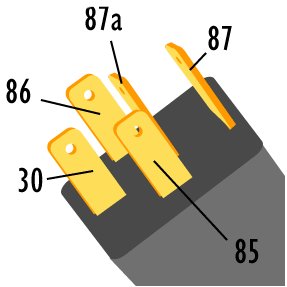
Now how is a relay energized to make this happen? With the "coil" contacts. On a standard 5-pin automotive relay they are labeled/called Pins 85 & 86. By putting a positive signal on one pin and a negative (or ground in this case) on the other pin the coil inside the relay is "on" and therefore the relay becomes energized connecting Common to NO. For most (and almost all) automotive relays it does not matter whether 85 or 86 get positive or negative; the coil inside is not polarized.
Recap of the pins and their labeling:
30 - Common
87a - Normaly Closed (NC)
87 - Normally Open (NO)
85 - Coil ( typically - )
86 - Coil (typically + )
This is a typical Automotive relay

This is what the bottom of the relay looks like, where the pins are seen (p.s. The drawing in my previous post has the pins oriented so as to depict what it would look like if you pointed the pins towards you, aka bottom view)
They also make mini relays to make it easier to hide them, which is especially useful if you don't plan on making long cable runs or using high current. The pins are still labeled and called the same, but the orientation is a little different. All you'd have to do is transpose what you'd normally hook up to your standard relay to the mini relay's pins. A lot easier than it sounds.

And there you have it. Switches and Relays 101
 If you or any other members have any questions feel free to ask away.

Thread
Thread Starter
Forum
Replies
Last Post
mada51589
3G TL Problems & Fixes
80
Jan 9, 2025 04:40 PM
akbears15
3G TL Audio, Bluetooth, Electronics & Navigation
15
Nov 5, 2015 07:06 AM
prox
5G TLX Problems & Fixes
6
Sep 1, 2015 02:03 AM