
DIY: Radio LED Conversion

Thread Starter
SOLD: 03 SSM CLS Auto
iTrader: (2)
Joined: Feb 2005
Posts: 1,095
Likes: 4
From: Texas
DIY: Radio LED Conversion
Hey guys, so I've been taking some time to put a DIY for a couple of things, first off will be my method of converting the stock radio in the 2nd Gen. CLs/TLs.
Ok, this is a very tedious task, and I recommend anyone who is not experienced with soldering to seriously ask yourself if you want to try this, because the consequences may be a totally useless radio.
Now, to start off you will need the following:
Eleven (11) 3mm at least 10,000mcd LEDs, in whatever color of your choice (or Thirteen (13) LEDs if you are wanting to make the rings around the knobs a different color).
The same amount of 560ohm 1/4watt resistors (11 or 13)
26 gauge Black solid or stranded wire, and 26 gauge Red solid or stranded wire (this is only required for the two tone look), 9volt battery, alligator clips (3).
A Soldering Iron (I used a 30watt all purpose from Radio Shack)
Electronics Solder (Also from Radio Shack), Superglue, Sharpie.
Wire cutters, wire stripper, needle nose pliers, Small/Medium Phillips screw driver, small Flat head screw driver, a Dremel, and lots of time and patience.
Now, If you�re looking to do this, you should already know how to take the center console out and remove the radio. If not, read up on it. I�d suggest disconnecting the battery first before taking anything apart, just in case. Oh, and make sure you have your radio�s anti-theft code.
Now that you have the radio out and on a good work space, you�re going to need to take the face of the radio off. In order to do that, you�ll have to take off the card holder tray which is connected to the radio (for those with Navi, I�m assuming the climate control is attached here instead, though it�s the same concept). Remove the two screws on either side:

Lift up on the card holder, and it will come off. Next you�ll need to unscrew the face of the radio from the metal housing. Take your screw driver and unscrew the four (4) screws through each hole on the side of the radio:

There�s two exactly the same on the other side.
Now, flip the radio up on its end, so the face of the radio is in the air. There are five (5) clips still holding the face in place, get your small flat head screw driver and gently pry up the clips on the top (they are indicated by arrows on the radio itself. While prying them up, gently push the face forward, so they dislodge from the housing. There are three clips on the top, and two clips on the bottom.

Now that all the clips are loose, the face should come right off. Here�s what the back of the face looks like:

Pull the knobs off of the front of the radio (may take some force, but they�ll pop off). There are six (6) screws holding the circuit board to the face of the radio. Unscrew them and place them in a safe place so they aren�t lost. Now the circuit board should just come out.
Each of the black rectangles are the bulbs for the radio. Underneath there is a plastic diffuser to spread the light out evenly. Here is what one of the holders looks like up close:

As you can see, the bulb leads are wrapped around the black holder, which is soldered onto the circuit board. We�ll need to take each of these out by wiggling them loose with your needle nose pliers. There is another bulb underneath the black felt piece above the connector plug. Peel up the felt, and you�ll see the black holder.
This is where it starts to get more complicated. Once all of the bulbs have been taken out (you can keep them if you want, maybe later you�ll want to put the radio back to stock?), you�ll need to take all of your LEDs and shave off the top part of the lens. This is to diffuse the light emitting from the LED to create a more dispersed beam, which will eliminate hot spots.
To do this, take your Dremel, with a sanding or grinding wheel:

One of these things, and take off as much of the lens as you can without exposing the diode (that will render the LED bulb useless). Once all of the bulbs have been shaved down, you�ll need to start warming up your soldering iron.
Now, take all of your LEDs and bend negative anode (shorter) out, and the positive anode (longer) down, like this:

You can also tell the negative end by the flat side of the LED (are you can see in the picture).
Now, take all of your resistors and bend the leads in towards each other so the ends cross, like this:

Now that you have all of this done, take your wire cutters and cut all of the leads of the LEDs to about a 1/4� long, and the resistors to about 1/8� long, like this:

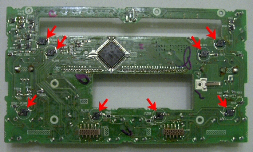
Your soldering iron should be good an hot by now, so we can start soldering! Before we actually start soldering, you�ll need to know which side is positive and which is negative. In the picture below each of the red dots indicates the positive side, where the resistor needs to be soldered to:

Remember, there is another bulb under the black felt, sorry, I didn�t take a picture without the felt, positive is on the right.
Now, Take one of your LEDs and place it into the whole with the negative anode facing the correct direction, and the positive facing out wards. You�ll need to put a little more solder on the circuit board connections (both positive and negative) in order for everything to hold together. Solder the negative side to the board.
Now you have the positive sticking anode of the LED sticking out to one side, with the positive connection above it. Take your resistor with your needle nose pliers (or tweezers may be easier to handle) and place it in the correct position, soldering it to the circuit board, then to the positive anode of the LED. Here is what it should look like when you�re done:


Repeat that same step for each of the other LEDs, using the same technique. This is where you are going to spend a lot of time hunched over your desk soldering. Take it slow, and try and keep a steady hand. Take a break if you have to, because it will be very tedious. If the LEDs are not pointing straight up when you flip the circuit board over, you can gently bend it in the right direction as not to break the solder connection.
Once you�re done with all the soldering, you might want to take a 9volt battery and some alligator clips, and test out the bulbs (I always like to have a resistor in between two clips connected to the positive, so not to burn out any LED not soldered correctly). Connect the positive to positive, negative to negative. If all goes well, the LEDs should all light up. The two LEDs for the screen are on a different circuit, so they should light up in sequence when current is run through them. If one of the bulbs doesn�t light, check your solder connections. If everything looks alright, I may have goofed on the positive and negative sides, so reverse the LED in the socket (sorry, that would be my bad), and try again.
__________________________________________________ _____________
Now, for those of you who are whole heartedly set on making you�re knobs a different color that the rest of the bulbs, read on. Though, there is another warning, this will require the mutilation of the clear light diffuser, and will not be able to be put back together if it is messed up. You�ll need your Dremel tool once again, this time using a cutting tool.
Take the last screw out of the radio face (it�s up at the top if you haven�t noticed it yet). Pop out the diffuser, keeping all of the buttons in their respective places while doing so. Set aside the face, and you�ll need this a little later on.

Now, you�re going to cut each side of the diffuser right below the circles for the knobs.


Once that is complete, you�ll need to place some Whiteout on both sides of the cut (this is to prevent the different colored light mixing together or drowning the other out). Should look something like this:


Now that that�s over with we can move on. Next step is to cut a notch out of the radio face so our LED will have a place to fit. Take your Dremel with the cutting tool again, and cut a notch right above the brace next to the whole for the knob, like this:

Place the top portion of the diffuser in place, and note where the notch is on the ring either by sight or you can place a very small dot with a sharpie. Do the same for the other side.
Next step is basically the same as the other LEDs, shave the lens down, bend the leads and cut them to about 1/4" long. Now you�re going to solder the resistor to the positive anode of the LED, and then solder about a 3 inch Red 26 gauge wire to the end of the resistor. To the negative anode, you�ll solder a 3 inch Black 26 gauge wire. Now you�ll need to get some superglue, and glue the LED to the ring of the diffuser at the very base where you noted the notch was. Wait till the glue dries, and see if everything fits into place like it should. If not, make adjustments accordingly.


Now, take your red wire, and solder it to the positive connection of one of the other LEDs already on the board (it�s best to solder it to the board, rather than the connection between the resistor and the LED already in place). Now solder the black wire to the same LED connection, but to the negative side. Now might be a good time to test your connections with the 9volt battery and alligator clips. If all is well, do the other side just the same. Now to put everything back together can be kind of tricky, but it�ll fit.
That�s just about it. Now all that needs to be done is place all of the screws back into place, place the face back onto the housing of the radio, and make sure none of the connections are touching and part of the metal housing (as this will most likely short out any of your LEDs and you�ll have to take everything back apart). Plug your radio back into your car, reconnect the battery and test it out! If all goes well, you�ll have a real slick looking radio.

If there are any questions, PM me, or email me at gaping46and2@gmail.com
I do have this in a PDF format, if someone can host it, that would be very helpful, or I can email it to anyone interested.
***I do not take any responsibility towards any mishaps while using this tutorial. This should be done at your own risk, and know that this could ruin your radio if it�s not done properly.***
Ok, this is a very tedious task, and I recommend anyone who is not experienced with soldering to seriously ask yourself if you want to try this, because the consequences may be a totally useless radio.
Now, to start off you will need the following:
Eleven (11) 3mm at least 10,000mcd LEDs, in whatever color of your choice (or Thirteen (13) LEDs if you are wanting to make the rings around the knobs a different color).
The same amount of 560ohm 1/4watt resistors (11 or 13)
26 gauge Black solid or stranded wire, and 26 gauge Red solid or stranded wire (this is only required for the two tone look), 9volt battery, alligator clips (3).
A Soldering Iron (I used a 30watt all purpose from Radio Shack)
Electronics Solder (Also from Radio Shack), Superglue, Sharpie.
Wire cutters, wire stripper, needle nose pliers, Small/Medium Phillips screw driver, small Flat head screw driver, a Dremel, and lots of time and patience.
Now, If you�re looking to do this, you should already know how to take the center console out and remove the radio. If not, read up on it. I�d suggest disconnecting the battery first before taking anything apart, just in case. Oh, and make sure you have your radio�s anti-theft code.
Now that you have the radio out and on a good work space, you�re going to need to take the face of the radio off. In order to do that, you�ll have to take off the card holder tray which is connected to the radio (for those with Navi, I�m assuming the climate control is attached here instead, though it�s the same concept). Remove the two screws on either side:
Lift up on the card holder, and it will come off. Next you�ll need to unscrew the face of the radio from the metal housing. Take your screw driver and unscrew the four (4) screws through each hole on the side of the radio:
There�s two exactly the same on the other side.
Now, flip the radio up on its end, so the face of the radio is in the air. There are five (5) clips still holding the face in place, get your small flat head screw driver and gently pry up the clips on the top (they are indicated by arrows on the radio itself. While prying them up, gently push the face forward, so they dislodge from the housing. There are three clips on the top, and two clips on the bottom.
Now that all the clips are loose, the face should come right off. Here�s what the back of the face looks like:
Pull the knobs off of the front of the radio (may take some force, but they�ll pop off). There are six (6) screws holding the circuit board to the face of the radio. Unscrew them and place them in a safe place so they aren�t lost. Now the circuit board should just come out.
Each of the black rectangles are the bulbs for the radio. Underneath there is a plastic diffuser to spread the light out evenly. Here is what one of the holders looks like up close:
As you can see, the bulb leads are wrapped around the black holder, which is soldered onto the circuit board. We�ll need to take each of these out by wiggling them loose with your needle nose pliers. There is another bulb underneath the black felt piece above the connector plug. Peel up the felt, and you�ll see the black holder.
This is where it starts to get more complicated. Once all of the bulbs have been taken out (you can keep them if you want, maybe later you�ll want to put the radio back to stock?), you�ll need to take all of your LEDs and shave off the top part of the lens. This is to diffuse the light emitting from the LED to create a more dispersed beam, which will eliminate hot spots.
To do this, take your Dremel, with a sanding or grinding wheel:
One of these things, and take off as much of the lens as you can without exposing the diode (that will render the LED bulb useless). Once all of the bulbs have been shaved down, you�ll need to start warming up your soldering iron.
Now, take all of your LEDs and bend negative anode (shorter) out, and the positive anode (longer) down, like this:
You can also tell the negative end by the flat side of the LED (are you can see in the picture).
Now, take all of your resistors and bend the leads in towards each other so the ends cross, like this:
Now that you have all of this done, take your wire cutters and cut all of the leads of the LEDs to about a 1/4� long, and the resistors to about 1/8� long, like this:
Your soldering iron should be good an hot by now, so we can start soldering! Before we actually start soldering, you�ll need to know which side is positive and which is negative. In the picture below each of the red dots indicates the positive side, where the resistor needs to be soldered to:
Remember, there is another bulb under the black felt, sorry, I didn�t take a picture without the felt, positive is on the right.
Now, Take one of your LEDs and place it into the whole with the negative anode facing the correct direction, and the positive facing out wards. You�ll need to put a little more solder on the circuit board connections (both positive and negative) in order for everything to hold together. Solder the negative side to the board.
Now you have the positive sticking anode of the LED sticking out to one side, with the positive connection above it. Take your resistor with your needle nose pliers (or tweezers may be easier to handle) and place it in the correct position, soldering it to the circuit board, then to the positive anode of the LED. Here is what it should look like when you�re done:
Repeat that same step for each of the other LEDs, using the same technique. This is where you are going to spend a lot of time hunched over your desk soldering. Take it slow, and try and keep a steady hand. Take a break if you have to, because it will be very tedious. If the LEDs are not pointing straight up when you flip the circuit board over, you can gently bend it in the right direction as not to break the solder connection.
Once you�re done with all the soldering, you might want to take a 9volt battery and some alligator clips, and test out the bulbs (I always like to have a resistor in between two clips connected to the positive, so not to burn out any LED not soldered correctly). Connect the positive to positive, negative to negative. If all goes well, the LEDs should all light up. The two LEDs for the screen are on a different circuit, so they should light up in sequence when current is run through them. If one of the bulbs doesn�t light, check your solder connections. If everything looks alright, I may have goofed on the positive and negative sides, so reverse the LED in the socket (sorry, that would be my bad), and try again.
__________________________________________________ _____________
Now, for those of you who are whole heartedly set on making you�re knobs a different color that the rest of the bulbs, read on. Though, there is another warning, this will require the mutilation of the clear light diffuser, and will not be able to be put back together if it is messed up. You�ll need your Dremel tool once again, this time using a cutting tool.
Take the last screw out of the radio face (it�s up at the top if you haven�t noticed it yet). Pop out the diffuser, keeping all of the buttons in their respective places while doing so. Set aside the face, and you�ll need this a little later on.
Now, you�re going to cut each side of the diffuser right below the circles for the knobs.
Once that is complete, you�ll need to place some Whiteout on both sides of the cut (this is to prevent the different colored light mixing together or drowning the other out). Should look something like this:
Now that that�s over with we can move on. Next step is to cut a notch out of the radio face so our LED will have a place to fit. Take your Dremel with the cutting tool again, and cut a notch right above the brace next to the whole for the knob, like this:
Place the top portion of the diffuser in place, and note where the notch is on the ring either by sight or you can place a very small dot with a sharpie. Do the same for the other side.
Next step is basically the same as the other LEDs, shave the lens down, bend the leads and cut them to about 1/4" long. Now you�re going to solder the resistor to the positive anode of the LED, and then solder about a 3 inch Red 26 gauge wire to the end of the resistor. To the negative anode, you�ll solder a 3 inch Black 26 gauge wire. Now you�ll need to get some superglue, and glue the LED to the ring of the diffuser at the very base where you noted the notch was. Wait till the glue dries, and see if everything fits into place like it should. If not, make adjustments accordingly.
Now, take your red wire, and solder it to the positive connection of one of the other LEDs already on the board (it�s best to solder it to the board, rather than the connection between the resistor and the LED already in place). Now solder the black wire to the same LED connection, but to the negative side. Now might be a good time to test your connections with the 9volt battery and alligator clips. If all is well, do the other side just the same. Now to put everything back together can be kind of tricky, but it�ll fit.
That�s just about it. Now all that needs to be done is place all of the screws back into place, place the face back onto the housing of the radio, and make sure none of the connections are touching and part of the metal housing (as this will most likely short out any of your LEDs and you�ll have to take everything back apart). Plug your radio back into your car, reconnect the battery and test it out! If all goes well, you�ll have a real slick looking radio.
If there are any questions, PM me, or email me at gaping46and2@gmail.com
I do have this in a PDF format, if someone can host it, that would be very helpful, or I can email it to anyone interested.
***I do not take any responsibility towards any mishaps while using this tutorial. This should be done at your own risk, and know that this could ruin your radio if it�s not done properly.***


Trending Topics

Senior Moderator
Joined: Aug 2002
Posts: 35,218
Likes: 15
From: Swansea, MA
If you get the PDF hosted, I can add the link to the first post... I'll let this sit here for a couple more days, but it's gotta go into the FAQ section (for safekeeping) soon 
Great reference
Great reference
White as night.
Joined: Jan 2006
Posts: 984
Likes: 0
From: Southern California
I'm here in spirit...
Joined: Mar 2005
Posts: 7,607
Likes: 0
From: CO
Great write up G46&2.
So does your white in the radio now match the stock lighting on the instruments and did you do the a/c screen as well? Looks like you did the clock.
I would love to do this in my Jeep if I had more steady hands.
So does your white in the radio now match the stock lighting on the instruments and did you do the a/c screen as well? Looks like you did the clock.
I would love to do this in my Jeep if I had more steady hands.
Don't Mess With Texas
Joined: Oct 2004
Posts: 4,600
Likes: 2
From: austin tx
Originally Posted by Lord Helmet
Great write up G46&2.
So does your white in the radio now match the stock lighting on the instruments and did you do the a/c screen as well? Looks like you did the clock.
I would love to do this in my Jeep if I had more steady hands.
So does your white in the radio now match the stock lighting on the instruments and did you do the a/c screen as well? Looks like you did the clock.
I would love to do this in my Jeep if I had more steady hands.
he has actually done mine as well, but it needs some fine tuning cause the colors didnt come out exactly right so i havent posted pics yet.
Thread Starter
SOLD: 03 SSM CLS Auto
iTrader: (2)
Joined: Feb 2005
Posts: 1,095
Likes: 4
From: Texas
Thanks for all the support guys, this write up did take a while to put together. When I get the time I'll try and make other's like it for other parts of the interior.
Thanks to Corrosion, the PDF version is now up on the net.
LH: All of the screens in the dash have had LEDs in them. I guess I just never had taken a picture with the a/c display on so anyone can see, but I assure you, they are there. If you come over to Texas sometime, maybe we can take your Jeep apart and see what we can do.
Thread Starter
SOLD: 03 SSM CLS Auto
iTrader: (2)
Joined: Feb 2005
Posts: 1,095
Likes: 4
From: Texas
Originally Posted by MSW 6SP
Would you install the LEDs on my car if I drove to Texas? Its just a hop, skip, and jump away! you cant turn down a guy that has the same birthday as you 
great write up, gaping
great write up, gaping
Haha, c'mon over. You can buy me lunch.
contrarian in fashion
Joined: Dec 2005
Posts: 9,861
Likes: 19
From: Los Angeles / Highland Park
i dont have a 2nd gen... but i gotta give it to you! not many people take the time and effort to do a DIY!
my hats off to you sir!
if u could get rep points here... id give it to you! LOL
my hats off to you sir!
if u could get rep points here... id give it to you! LOL
Banned
Joined: Feb 2006
Posts: 1,439
Likes: 0
From: Tampa, FL
OMG... The circuit board on your CL's radio looks alot better than the board that's in the TL... Looks more like the Accord's radio. I went through raw hell trying to figure things out with mine. Everything's straight forward and easy to get to for yours.
Hope you don't mind me showing you what I mean.. here's your radio board:
Here's the Honda accord... a little more difficult, but everything's still easy to get to..
When you look at an older TL's HU.... there's alot more clutter than you can see in the Accord's HU. Glad the install was easy for you.. never again will I touch my headunit. lol Once I start taking the car apart, I'll take pics of the headunit for you so you can see what I mean.


2014 TL SH-AWD Advance

Joined: Dec 2006
Posts: 291
Likes: 18
From: Charleston, IL
Have you thought about buying a spare radio, doing the conversion, and selling this to members? You know, like have one or more spares that you convert, charge a set price, plus refundable core charge. I'm pretty good with a soldering gun, but don't really have the time to jack around with something like this. If you could crank out some of these I bet the people who aren't comfortable in doing this would be interested in swapping their non-modded radio for your converted radio, for a fee.
Thread Starter
SOLD: 03 SSM CLS Auto
iTrader: (2)
Joined: Feb 2005
Posts: 1,095
Likes: 4
From: Texas
Originally Posted by 03sixer
Have you thought about buying a spare radio, doing the conversion, and selling this to members? You know, like have one or more spares that you convert, charge a set price, plus refundable core charge. I'm pretty good with a soldering gun, but don't really have the time to jack around with something like this. If you could crank out some of these I bet the people who aren't comfortable in doing this would be interested in swapping their non-modded radio for your converted radio, for a fee.
That is an idea I've been considering for some time now, though it would be a very time consuming process. I've been meaning to put up a feeler thread here and on the tl boards about this just to see how many people might be interested in something like this.

10th Gear
Joined: Feb 2007
Posts: 10
Likes: 0
hey I was just wondering if you could give me any pointers on taking the radio out, the rest seems pretty easy but tedious with oyur instructions my only problem is getting the radio out. you think youi could give me some tips?
also on the the shift gate I saw that there is a guy who did put the LEDs in the shift gate I was wondering if you know how to take that apart also.
thanks for your time
and is it possible to do this to the dash display?
also on the the shift gate I saw that there is a guy who did put the LEDs in the shift gate I was wondering if you know how to take that apart also.
thanks for your time
and is it possible to do this to the dash display?
03 3.2 CL Type-S (AT)
Joined: Dec 2006
Posts: 105
Likes: 0
From: Birmingham, AL
For the dash:
http://www.ledautomotive.com/OrderInfo/
http://www.ledautomotive.com/OrderInfo/
03 3.2 CL Type-S (AT)
Joined: Dec 2006
Posts: 105
Likes: 0
From: Birmingham, AL
How to do the shift gate:
https://acurazine.com/forums/ramblings-12/so-im-assuming-all-madden-heads-have-been-busy-150446/
https://acurazine.com/forums/ramblings-12/so-im-assuming-all-madden-heads-have-been-busy-150446/
Thread Starter
SOLD: 03 SSM CLS Auto
iTrader: (2)
Joined: Feb 2005
Posts: 1,095
Likes: 4
From: Texas
Originally Posted by badacura01typeS
hey I was just wondering if you could give me any pointers on taking the radio out, the rest seems pretty easy but tedious with oyur instructions my only problem is getting the radio out. you think youi could give me some tips?
also on the the shift gate I saw that there is a guy who did put the LEDs in the shift gate I was wondering if you know how to take that apart also.
thanks for your time
and is it possible to do this to the dash display?
also on the the shift gate I saw that there is a guy who did put the LEDs in the shift gate I was wondering if you know how to take that apart also.
thanks for your time
and is it possible to do this to the dash display?


Thread Starter
SOLD: 03 SSM CLS Auto
iTrader: (2)
Joined: Feb 2005
Posts: 1,095
Likes: 4
From: Texas
It's come to my attention the link to the PDF version of the DIY is dead. I hope this one will work:
Radio LED pdf
Radio LED pdf
Advanced
Joined: Jun 2008
Posts: 98
Likes: 0
From: Saskatchewan, Canada
"you’ll need to take all of your LEDs and shave off the top part of the lens. This is to diffuse the light emitting from the LED to create a more dispersed beam, which will eliminate hot spots. "
What if instead I would use these?
http://cgi.ebay.com.au/20x-3mm-White...3286.m63.l1177
Would I still need to shave the tops off?
What if instead I would use these?
http://cgi.ebay.com.au/20x-3mm-White...3286.m63.l1177
Would I still need to shave the tops off?
Thread Starter
SOLD: 03 SSM CLS Auto
iTrader: (2)
Joined: Feb 2005
Posts: 1,095
Likes: 4
From: Texas
"you�ll need to take all of your LEDs and shave off the top part of the lens. This is to diffuse the light emitting from the LED to create a more dispersed beam, which will eliminate hot spots. "
What if instead I would use these?
http://cgi.ebay.com.au/20x-3mm-White...3286.m63.l1177
Would I still need to shave the tops off?
What if instead I would use these?
http://cgi.ebay.com.au/20x-3mm-White...3286.m63.l1177
Would I still need to shave the tops off?

Advanced
Joined: Jun 2008
Posts: 98
Likes: 0
From: Saskatchewan, Canada

Thread Starter
SOLD: 03 SSM CLS Auto
iTrader: (2)
Joined: Feb 2005
Posts: 1,095
Likes: 4
From: Texas
Extremely cost prohibitive. The time it takes for one person to do this sort of stuff, you'd either start a business, doing this and only this, or REALLY have a lot of free time and desperate for a hobby.
That's one reason I made a DIY, so others can follow along and do it themselves. It's really not difficult, just takes a bit of soldering skill and quite a bit of free time.
That's one reason I made a DIY, so others can follow along and do it themselves. It's really not difficult, just takes a bit of soldering skill and quite a bit of free time.
Last edited by gaping46and2; Sep 19, 2009 at 09:58 PM.
Extremely cost prohibitive. The time it takes for one person to do this sort of stuff, you'd either start a business, doing this and only this, or REALLY have a lot of free time and desperate for a hobby.
That's one reason I made a DIY, so others can follow along and do it themselves. It's really not difficult, just takes a bit of soldering skill and quite a bit of free time.
That's one reason I made a DIY, so others can follow along and do it themselves. It's really not difficult, just takes a bit of soldering skill and quite a bit of free time.
Thread Starter
SOLD: 03 SSM CLS Auto
iTrader: (2)
Joined: Feb 2005
Posts: 1,095
Likes: 4
From: Texas