


DIY: White front sidemarkers (best thread!)



DIY: White front sidemarkers (best thread!)
Okay so I have read the past threads with white LED modification in the front sidemarkers but I have never been happy with them, the LEDs either die out, or it requires adding a whole new strip in place. I have a background in electrical and pretty mechanically inclined so I was sure I can invent a better way myself. I will also explain why people's white LEDs always failed in the past and how I plan to improve on that. I have custom made my dome LEDs with pirahna superflux white LEDs so I have plenty left over to use in my sidemarkers. Here is my thread of the dome LEDs: https://acurazine.com/forums/3g-tl-2004-2008-93/made-some-custom-leds-849785/
Anyways, so I began the project and took out the circuit board inside, I began to analyze why people's LEDs always failed in the past. It turns out there are three 389 Ohm resistors in parallel for the LEDs, and after doing some calculation, it will give the circuit 55.4 mA to each LED. The optimal value for an LED is 20mA, so 55.4 is way too higher thus leading to flickering and burnt out LEDs. I decided 1 resistor was enough so I removed the three stock resistors and I went with a single 330 Ohm resistor to take the place. With this value, I guarantee the LEDs will NOT burn out and retains most OEM parts. I'll let the pictures speak for themselves, and I've included a picture of my calculations for any engineers here to analyze.
Before:

Cut open, very easy, no trouble here:


Testing the resistance of the stock resistors:

Calculations:

Stock amber LEDs removed:


Soldered on new 330 Ohm resistor:

Soldered on new white LEDs:

All done!:

Anyways, so I began the project and took out the circuit board inside, I began to analyze why people's LEDs always failed in the past. It turns out there are three 389 Ohm resistors in parallel for the LEDs, and after doing some calculation, it will give the circuit 55.4 mA to each LED. The optimal value for an LED is 20mA, so 55.4 is way too higher thus leading to flickering and burnt out LEDs. I decided 1 resistor was enough so I removed the three stock resistors and I went with a single 330 Ohm resistor to take the place. With this value, I guarantee the LEDs will NOT burn out and retains most OEM parts. I'll let the pictures speak for themselves, and I've included a picture of my calculations for any engineers here to analyze.
Before:
Cut open, very easy, no trouble here:
Testing the resistance of the stock resistors:
Calculations:
Stock amber LEDs removed:
Soldered on new 330 Ohm resistor:
Soldered on new white LEDs:
All done!:







Trending Topics

Sure, yours may work, but i went with the OG thread that used Oznium LED's for the simple fact that the led module runs off 12v and it has more leds, so no hot spots showing when lit up.
I have had no problems in 4 years now with the oznium LED modules. Thanks for your contribution.
I have had no problems in 4 years now with the oznium LED modules. Thanks for your contribution.




I'm definitely in for the post install pics. This seems to be a very easy method, just soldering a couple things on and closing back up, not unlike the LED turn signal relay mod. Hardest part is likely just opening and closing the lights (or maybe pulling them from the car? Not sure, never removed mine...)
I wanna see pics too. Some members say it might have hot spots compared to oznium module which is believable. Pics will prove if its true or not. I do like this method since its far less expensive than buying LED module, but its a little more work since you have to desolder, solder, and figure out what size resistor is needed.
Using the LED module method is as easy as just taping it ontop of the LED board and from there the user can decide if he wants to do the solder method or just wire it like I did.
The con to the LED module is its not true pure white. It's more of a 6,000-6,500k white. I would probably do your method sometime in the future because I don't like the "white" the oznium bars produce, and you say yours are 5,000k pure white with no hint of blue or purple
Using the LED module method is as easy as just taping it ontop of the LED board and from there the user can decide if he wants to do the solder method or just wire it like I did.
The con to the LED module is its not true pure white. It's more of a 6,000-6,500k white. I would probably do your method sometime in the future because I don't like the "white" the oznium bars produce, and you say yours are 5,000k pure white with no hint of blue or purple

the overexplainer
Joined: Feb 2011
Posts: 3,287
Likes: 385
From: OC, CA
my OEM side markers dim occasionally or dont turn on at all. If I have them on long enough eventually they'll come to full brightness.
What could be wrong? Would it be possible to repair/replace the LEDs inside?
IIRC a OEM replacement is around $45.
What could be wrong? Would it be possible to repair/replace the LEDs inside?
IIRC a OEM replacement is around $45.
Sure, yours may work, but i went with the OG thread that used Oznium LED's for the simple fact that the led module runs off 12v and it has more leds, so no hot spots showing when lit up.
I have had no problems in 4 years now with the oznium LED modules. Thanks for your contribution.
I have had no problems in 4 years now with the oznium LED modules. Thanks for your contribution.
LOL!!!
I'm definitely in for the post install pics. This seems to be a very easy method, just soldering a couple things on and closing back up, not unlike the LED turn signal relay mod. Hardest part is likely just opening and closing the lights (or maybe pulling them from the car? Not sure, never removed mine...)
yes, I'm 100% sure it's possible, you can have my old amber LEDs if you want lol, but if you cut it open you might as well replace with white LEDs.
I wanna see pics too. Some members say it might have hot spots compared to oznium module which is believable. Pics will prove if its true or not. I do like this method since its far less expensive than buying LED module, but its a little more work since you have to desolder, solder, and figure out what size resistor is needed.
Using the LED module method is as easy as just taping it ontop of the LED board and from there the user can decide if he wants to do the solder method or just wire it like I did.
The con to the LED module is its not true pure white. It's more of a 6,000-6,500k white. I would probably do your method sometime in the future because I don't like the "white" the oznium bars produce, and you say yours are 5,000k pure white with no hint of blue or purple
Using the LED module method is as easy as just taping it ontop of the LED board and from there the user can decide if he wants to do the solder method or just wire it like I did.
The con to the LED module is its not true pure white. It's more of a 6,000-6,500k white. I would probably do your method sometime in the future because I don't like the "white" the oznium bars produce, and you say yours are 5,000k pure white with no hint of blue or purple
Here are some pics:



Engineer in Training
Joined: Mar 2012
Posts: 599
Likes: 127
From: Long Island, NY
Very nice! I like people taking the initiative to hack their own equipment. The saying after all is, If you don't hack it, You don't own it.
Paperboy, just so you know for next time, don't hold the resistors you are measuring, you will throw off the resistance a bit. Either read the color bands or measure the resistance across the resistor while it's still in the PCB. The value won't be affected by the surrounding circuit if you place your leads right on the resistor instead of somewhere else on the board.
Great job!!
Paperboy, just so you know for next time, don't hold the resistors you are measuring, you will throw off the resistance a bit. Either read the color bands or measure the resistance across the resistor while it's still in the PCB. The value won't be affected by the surrounding circuit if you place your leads right on the resistor instead of somewhere else on the board.
Great job!!

Engineer in Training
Joined: Mar 2012
Posts: 599
Likes: 127
From: Long Island, NY
You could also use a solder sucker but they suck

Thanks LockDots. Looking forward to this mod, seems pretty easy!
Paperboy - happen to have links to where you got the LEDs and resistors from?
Edit: Looks like these are the LEDs, but I still don't know what wattage resistor should be used.
http://lighthouseleds.com/5mm-piranh...2-000-mcd.html
Paperboy - happen to have links to where you got the LEDs and resistors from?
Edit: Looks like these are the LEDs, but I still don't know what wattage resistor should be used.
http://lighthouseleds.com/5mm-piranh...2-000-mcd.html
Last edited by KJ TL-S; Jan 3, 2013 at 08:40 AM.
Engineer in Training
Joined: Mar 2012
Posts: 599
Likes: 127
From: Long Island, NY
Thanks LockDots. Looking forward to this mod, seems pretty easy!
Paperboy - happen to have links to where you got the LEDs and resistors from?
Edit: Looks like these are the LEDs, but I still don't know what wattage resistor should be used.
http://lighthouseleds.com/5mm-piranh...2-000-mcd.html
Paperboy - happen to have links to where you got the LEDs and resistors from?
Edit: Looks like these are the LEDs, but I still don't know what wattage resistor should be used.
http://lighthouseleds.com/5mm-piranh...2-000-mcd.html
Engineer in Training
Joined: Mar 2012
Posts: 599
Likes: 127
From: Long Island, NY
 no problem, I just blurt stuff out sometimes. If you use the OP's measurements and resistance values the current through the resistor is about 55mA with a voltage of about 8V. 55mA x 8V = 440mW so a resistor that can handle 880mW should suffice. This however, is not a standard value and the next closest 1W which is even safer. So, in short a 1W resistor should be fine.
Thanks! Just ordered the LEDs, resistors, and the copper braid all from that site, for less than $8 shipped, including extra of all the parts, just in case.
Now I just need the material/epoxy that gets used to put the sidemarker back together and I'll be set.
Now I just need the material/epoxy that gets used to put the sidemarker back together and I'll be set.


Phmbm12
Joined: May 2009
Posts: 740
Likes: 26
From: West Valley City, UT
i have zero experience in soldering and in watts/ohms and stuff. if you could direct me to where you got the leds and the ohms resistor things, i'll have my friend do it for me haha.
i just dont wanna buy the wrong thing and have something blow up
i just dont wanna buy the wrong thing and have something blow up
Here is what I bought, hopefully it is all correct:
LEDs: http://lighthouseleds.com/5mm-piranh...2-000-mcd.html
Resistors: http://lighthouseleds.com/1-watt-met...tolerance.html 330ohm variety
Copper Braid: http://lighthouseleds.com/desolder-braid-5-feet.html
LEDs: http://lighthouseleds.com/5mm-piranh...2-000-mcd.html
Resistors: http://lighthouseleds.com/1-watt-met...tolerance.html 330ohm variety
Copper Braid: http://lighthouseleds.com/desolder-braid-5-feet.html
Engineer in Training
Joined: Mar 2012
Posts: 599
Likes: 127
From: Long Island, NY
Easy, just need a relay. I'm going to do this mod on my car soon soon. In the meantime I can put up a wiring diagram/schematic if you want to wire it up yourself and post pictures for everyone else.
edit: just realized you meant switchbacks, not just turn signals. so that stuff up there^^? forget it lol
edit: just realized you meant switchbacks, not just turn signals. so that stuff up there^^? forget it lol
Last edited by LockDots; Jan 3, 2013 at 12:56 PM.
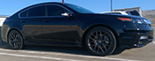
Now I am contemplating re-doing my side markers with this method since it's closer to 5k white compared to the Oznium modules which are far from pure white... They look friggin purple during the day for goodness sakes!
Can you post some night time pics of the side markers
Can you post some night time pics of the side markers
Last edited by vietxquangstah; Jan 4, 2013 at 12:20 AM.
no problem, I just blurt stuff out sometimes. If you use the OP's measurements and resistance values the current through the resistor is about 55mA with a voltage of about 8V. 55mA x 8V = 440mW so a resistor that can handle 880mW should suffice. This however, is not a standard value and the next closest 1W which is even safer. So, in short a 1W resistor should be fine.Based on these equations, a 1/4 watt resistor(which is what I used), is definitely more than adequate. I think that is why the stock circuit had 3 resistors in parallel, because the stock circuit is designed for 55mA which based on your calculations, required almost 1/2 watt. The stock resistors are 1/4W so having 3 in parallel was adequate.
Haha the cold weather recently makes me not want to wash my car!
Thanks for the advice, I held it in my fingers for the picture, but yea you are right.
I got my LEDs from ebay, just get the warm white to get the same color as mine. a 1/4W resistor is enough for this job. The one you linked seems to be a "cool white" though so it might be closer to 6000k.
LEDs from ebay, resistors I got from my friend's shop but you can get them anywhere, just get one ~330 Ohms, 1/4W.
I'd post pics at night but you know how cameraphones are for nighttime pics, its a bunch of blurs/glares most of the time lol, and I have an iphone 4S so its not like a crappy camera on a phone
Very nice! I like people taking the initiative to hack their own equipment. The saying after all is, If you don't hack it, You don't own it.
Paperboy, just so you know for next time, don't hold the resistors you are measuring, you will throw off the resistance a bit. Either read the color bands or measure the resistance across the resistor while it's still in the PCB. The value won't be affected by the surrounding circuit if you place your leads right on the resistor instead of somewhere else on the board.
Great job!!
Paperboy, just so you know for next time, don't hold the resistors you are measuring, you will throw off the resistance a bit. Either read the color bands or measure the resistance across the resistor while it's still in the PCB. The value won't be affected by the surrounding circuit if you place your leads right on the resistor instead of somewhere else on the board.
Great job!!
Thanks LockDots. Looking forward to this mod, seems pretty easy!
Paperboy - happen to have links to where you got the LEDs and resistors from?
Edit: Looks like these are the LEDs, but I still don't know what wattage resistor should be used.
http://lighthouseleds.com/5mm-piranh...2-000-mcd.html
Paperboy - happen to have links to where you got the LEDs and resistors from?
Edit: Looks like these are the LEDs, but I still don't know what wattage resistor should be used.
http://lighthouseleds.com/5mm-piranh...2-000-mcd.html
Now I am contemplating re-doing my side markers with this method since it's closer to 5k white compared to the Oznium modules which are far from pure white... They look friggin purple during the day for goodness sakes!
Can you post some night time pics of the side markers
Can you post some night time pics of the side markers
Engineer in Training
Joined: Mar 2012
Posts: 599
Likes: 127
From: Long Island, NY
The current after installing the new 330 ohm resistor will not be 55mA anymore, it would be ~20mA. Using P=V^2/R, the resistor only needs to take about 0.16W of power. Your P=IV also works but it would be 0.02A x 7.6= 0.152W
Based on these equations, a 1/4 watt resistor(which is what I used), is definitely more than adequate. I think that is why the stock circuit had 3 resistors in parallel, because the stock circuit is designed for 55mA which based on your calculations, required almost 1/2 watt. The stock resistors are 1/4W so having 3 in parallel was adequate.
Based on these equations, a 1/4 watt resistor(which is what I used), is definitely more than adequate. I think that is why the stock circuit had 3 resistors in parallel, because the stock circuit is designed for 55mA which based on your calculations, required almost 1/2 watt. The stock resistors are 1/4W so having 3 in parallel was adequate.
So I don't really know what the differences really mean, but will the 1 watt resistors I ordered work? Or should they be 1/4 watt? I also might order those warm whites off eBay, don't want them to end up looking purple, and I only feel like doing this once.

Engineer in Training
Joined: Mar 2012
Posts: 599
Likes: 127
From: Long Island, NY
you'll be fine. You can go up in Power Rating (wattage), not down.