
Valentine-1 Concealed Main Unit with Hidden Display: Step by Step WITH PICTURES

Thread Starter
The Voice of Reason
Joined: Aug 2003
Posts: 879
Likes: 0
Valentine-1 Concealed Main Unit with Hidden Display: Step by Step WITH PICTURES
Valentine-1 Concealed Main Unit with Hidden Display: Step by Step Instructions WITH PICTURES.
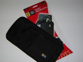
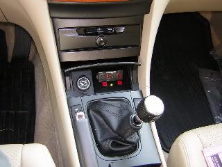
I hardwired my V-1 and mounted the remote display in the space in the console formerly occupied by the fuzzy red �Not An Ashtray� coin tray that we in the PC USA get in place of an ashtray. At most this requires sacrifice of the coin holder or ashtray, well worth it IMO. To each his own vice. My main V-1 unit is located in the pocket of a Case Logic visor organizer ($7.99, Target Stores), the cord is routed down behind the trim of the "A" pillar, behind the glove box and into the console. The power source I used is the wires for the front accessory power socket connector. It�s completely invisible if you close the door of the coin pocket holder!
Standard dIsclaimer: This is how I did it, I don�t know if your skill level is greater or less than mine, so I don�t necessarily recommend that you attempt this. So if you try this and break something or blow anything up or maim kill or disfigure yourself you�re on your own!
I also installed the cassette tape player when I was doing this, many of the same pieces need to be removed. Honda Acura World-Dot-com has installation instructions online.
Tools:
Thin-blade putty knives
Dremel Moto-Tool
Helms TSX Service Manual (HIGHLY recommended)
Materials:
V-1
V-1Concealed Display
V-1 Wiring harness
3M wire taps
HD Velcro pads
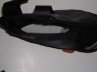
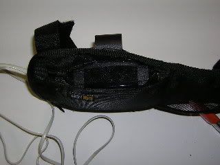
1 Case Logic Visor Organizer
1 Sheet black felt
7� Telephone cord
1� Telephone cord
Cable ties
Electrical Tape
Duct Tape
Masking tape
1. DISCONNECT BATTERY!!!!
2. Pull down weather strip on front edge of passenger�s door frame
3. Pull up front pillar cap on �A� pillar and pull off �A� pillar trim
4. Remove glovebox stops.
5. Disconnect glove box damper.
6. Pop off side cover of dashboard
7. Remove screw and pop off side cover of console in passenger�s footwell.
8. CAREFULLY remove console storage box (pulls out), Don�t pull on lid.
9. Unscrew shift knob.
10. CAREFULLY remove console top (pulls up)
11. Disconnect seat heater switches.
12. Remove 4 Phillips screws from coin pocket holder assembly.
13. Disconnect power socket connector. Remove Coin Pocket Holder.
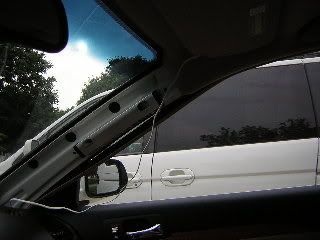
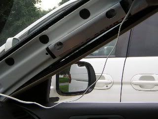
14. Note that head airbag occupies top 1/3 and rearmost 1/2 of �A� pillar. Leaving about 10-15 cm. of slack cord, duct tape one end of 7� telephone wire forward of airbag assembly. Route wire down A pillar in front of trim clip holes, again keeping on place with duct tape. Route wire into dash, behind glove box and into center console.
15. Pop red felt coin holder out of assembly.
16. Using Dremel, cut out entire back of coin pocket holder.
17. Now is also a good time to cut a cardboard template for the plastic piece to fill the tray. (You may wish to cover the wires visible behind the concealed display.)
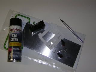
18. Fabricate a plastic plug and aluminum bracket to mount the V-1, LE-30 status diode and kill switches for the �Not An Ashtray� holder, and paint it using black interior trim paint.
19. Unwrap electrical tape from power socket wire. Press 3M wire taps into wires. I modified the V-1 wiring harness by adding a second spade connector. Insert spade connectors into wire taps, wrap everything in electrical tape.
20. Plug 7� and 1� telephone cords into V-1 harness.
21. Pull V-1 fuse holder thru 1� hole an into pocket of coin holder assembly. Secure with cable tie.
22. Pull 1� phone cord thru hole.
23. Attach HD Velcro to V-1 Concealed Display and coin tray assembly.
24. Plug telephone cord into V-1 display.
25, Replace 4 Phillips head screws for coin pocket holder assembly.
26. Cut black felt to size to cover unsightly bundle of wires.
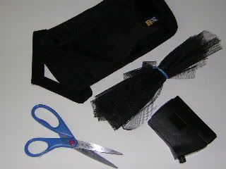
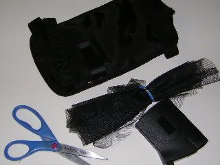
27. Cut 4 cm. slit in the top of the Visor Organizer at the leading edge for the visor mount and a 1cm slit on the window side for the cord. Cut a �window� for the front LIDAR detector (microwaves will travel through the material, LIDAR won�t. I also glued black nylon netting over the �window�.
28. Mount visor clip on visor.
29. Mount visor organizer on visor.
30. Insert cord thru hole.
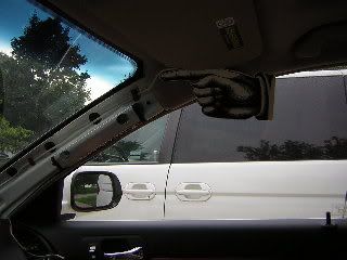
31. Slide V-1 into visor bracket.
32. Plug telephone cable into V-1.
Next, as they say in the Haynes manuals �Reassembly is (Simply!) the reverse of disassembly�!
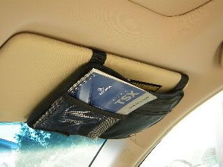
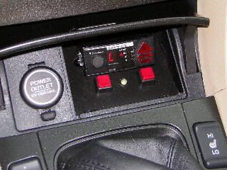
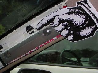
Valentine-1 remote display
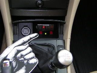
Power switch (for Valentine-1)
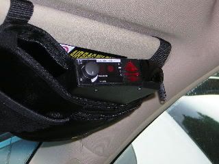
Now you see it....
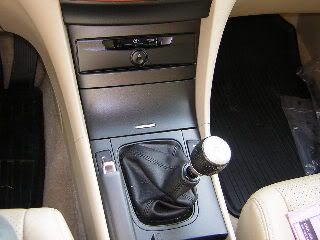
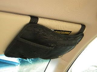
...and now you don�t!
I hardwired my V-1 and mounted the remote display in the space in the console formerly occupied by the fuzzy red �Not An Ashtray� coin tray that we in the PC USA get in place of an ashtray. At most this requires sacrifice of the coin holder or ashtray, well worth it IMO. To each his own vice. My main V-1 unit is located in the pocket of a Case Logic visor organizer ($7.99, Target Stores), the cord is routed down behind the trim of the "A" pillar, behind the glove box and into the console. The power source I used is the wires for the front accessory power socket connector. It�s completely invisible if you close the door of the coin pocket holder!
Standard dIsclaimer: This is how I did it, I don�t know if your skill level is greater or less than mine, so I don�t necessarily recommend that you attempt this. So if you try this and break something or blow anything up or maim kill or disfigure yourself you�re on your own!
I also installed the cassette tape player when I was doing this, many of the same pieces need to be removed. Honda Acura World-Dot-com has installation instructions online.
Tools:
Thin-blade putty knives
Dremel Moto-Tool
Helms TSX Service Manual (HIGHLY recommended)
Materials:
V-1
V-1Concealed Display
V-1 Wiring harness
3M wire taps
HD Velcro pads
1 Case Logic Visor Organizer
1 Sheet black felt
7� Telephone cord
1� Telephone cord
Cable ties
Electrical Tape
Duct Tape
Masking tape
1. DISCONNECT BATTERY!!!!
2. Pull down weather strip on front edge of passenger�s door frame
3. Pull up front pillar cap on �A� pillar and pull off �A� pillar trim
4. Remove glovebox stops.
5. Disconnect glove box damper.
6. Pop off side cover of dashboard
7. Remove screw and pop off side cover of console in passenger�s footwell.
8. CAREFULLY remove console storage box (pulls out), Don�t pull on lid.
9. Unscrew shift knob.
10. CAREFULLY remove console top (pulls up)
11. Disconnect seat heater switches.
12. Remove 4 Phillips screws from coin pocket holder assembly.
13. Disconnect power socket connector. Remove Coin Pocket Holder.
14. Note that head airbag occupies top 1/3 and rearmost 1/2 of �A� pillar. Leaving about 10-15 cm. of slack cord, duct tape one end of 7� telephone wire forward of airbag assembly. Route wire down A pillar in front of trim clip holes, again keeping on place with duct tape. Route wire into dash, behind glove box and into center console.
15. Pop red felt coin holder out of assembly.
16. Using Dremel, cut out entire back of coin pocket holder.
17. Now is also a good time to cut a cardboard template for the plastic piece to fill the tray. (You may wish to cover the wires visible behind the concealed display.)
18. Fabricate a plastic plug and aluminum bracket to mount the V-1, LE-30 status diode and kill switches for the �Not An Ashtray� holder, and paint it using black interior trim paint.
19. Unwrap electrical tape from power socket wire. Press 3M wire taps into wires. I modified the V-1 wiring harness by adding a second spade connector. Insert spade connectors into wire taps, wrap everything in electrical tape.
20. Plug 7� and 1� telephone cords into V-1 harness.
21. Pull V-1 fuse holder thru 1� hole an into pocket of coin holder assembly. Secure with cable tie.
22. Pull 1� phone cord thru hole.
23. Attach HD Velcro to V-1 Concealed Display and coin tray assembly.
24. Plug telephone cord into V-1 display.
25, Replace 4 Phillips head screws for coin pocket holder assembly.
26. Cut black felt to size to cover unsightly bundle of wires.
27. Cut 4 cm. slit in the top of the Visor Organizer at the leading edge for the visor mount and a 1cm slit on the window side for the cord. Cut a �window� for the front LIDAR detector (microwaves will travel through the material, LIDAR won�t. I also glued black nylon netting over the �window�.
28. Mount visor clip on visor.
29. Mount visor organizer on visor.
30. Insert cord thru hole.
31. Slide V-1 into visor bracket.
32. Plug telephone cable into V-1.
Next, as they say in the Haynes manuals �Reassembly is (Simply!) the reverse of disassembly�!
Valentine-1 remote display
Power switch (for Valentine-1)
Now you see it....
...and now you don�t!

Thread Starter
The Voice of Reason
Joined: Aug 2003
Posts: 879
Likes: 0
Originally Posted by elduderino
Nice writeup, Dan. Looks functional and stealth.
Now, can you gut the V1 and put the sensors in place without the whole unit up there? : )
Now, can you gut the V1 and put the sensors in place without the whole unit up there? : )

Since the antennas are about the same height as the entire unit, there isn't an awful lot to gain by ditching the case, anyway. Mike Valentine also seems to discourage this.
If the V-1 is located in the visor organizer the overall thickness really isn't noticable. Other, more stealthy locations I've seen used by Virginians are in a headrest, and under (M5) and on the rear package shelf, either disguised as an additional speaker or under a baseball cap. Problem is that there is "some" degradation of performance the lower the radar antennas are mounted. (As opposed to the Laser jammer, that you want to mount low because they aim at the front license plate!)
Suzuka Master
Joined: Mar 2003
Posts: 6,897
Likes: 1
From: Austin, TX
So, Bob, when do you want to come to Austin? (nice install by the way).
I think I just want to hide my wire after I just have it mounted near the rearview mirror, but just bury the cord. I'm just funny about taking apart my interior (though I have no issues with fucking up the ECU).
I think I just want to hide my wire after I just have it mounted near the rearview mirror, but just bury the cord. I'm just funny about taking apart my interior (though I have no issues with fucking up the ECU).

Trending Topics
Rep'n Taxbrain.com
Joined: Aug 2004
Posts: 7,075
Likes: 3
From: N. Cali-forn-i-a
Hey Bob,
I noticed that you have the OEM cassette player. I'm thinking about buying the Acura OEM installation kit normally used for the cassette/mp3 player and putting an Pioneer AVIC-N1 with NAvi/dvd/mp3/ 6.5" screen there.
Do you think the unit will fit. How long is the factory cassette player. Is is the size of a standard aftermarket radio?
Thanks a lot!! Kenny

Thread
Thread Starter
Forum
Replies
Last Post
rockyboy
2G RDX (2013-2018)
46
Jan 25, 2016 06:00 PM
Oakes
Wash & Wax
10
Oct 12, 2015 11:17 AM
Yumcha
Automotive News
1
Sep 17, 2015 09:01 PM