
G-003: DI: Independent fog lights from headlights mod -> Pictures!
 11-14-2010, 08:30 PM
#1
Gets bored easily
Thread Starter
On the 2nd gen TSX, the fog lights are effectively integrated into the rest of the car's lighting, such that a simple rewire of the foglights using only the existing wiring and switches is not possible (as far as I could tell). As such, I wired in a separate relay and switch in order to have the fog lights operate independently of any other lights. The fogs can now be run with no other lights, parks only, and low and high beams.
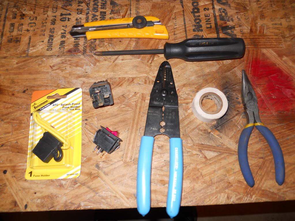
What you'll need:
Wire strippers/cutters
Utility knife
Electrical tape (black would be best, all I had was white laying around)
Awl (not pictured)
Needlenose pliers
Switch
12v relay (any generic five terminal relay will do)
Fuseable link and 10A fuse
Flathead screwdriver
Wire
I wanted to maintain the ability to switch the fogs off if I wanted, so I hid the switch inside the cabin above the passenger's feet. You could put the switch anywhere of course; this was the easiest spot for me right now. If you look at the engine compartment side of the firewall, you'll see two rubber grommets with one bundle of wires going through each. The one near the center of the car was too difficult for me to get to in the interior, so I chose to use the grommet on passenger side.
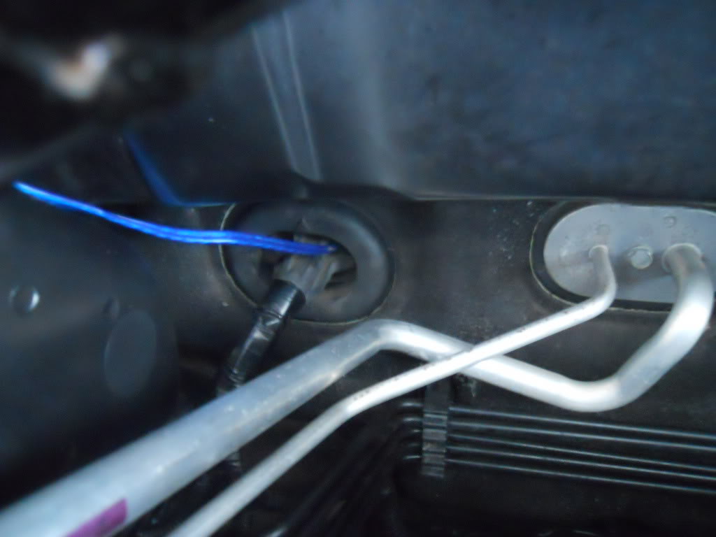
Above you see my new wires already running through the grommet. Here's how I did it:
1. Remove the panel above the passenger footwell. You'll see a lot of plastic ductwork. Remove the center screw at the bottom of this ductwork, as well as the nut on the right side bottom. This should allow you to move the ducts a little bit. You'll need to stick your hand behind the ducts to route the wires.
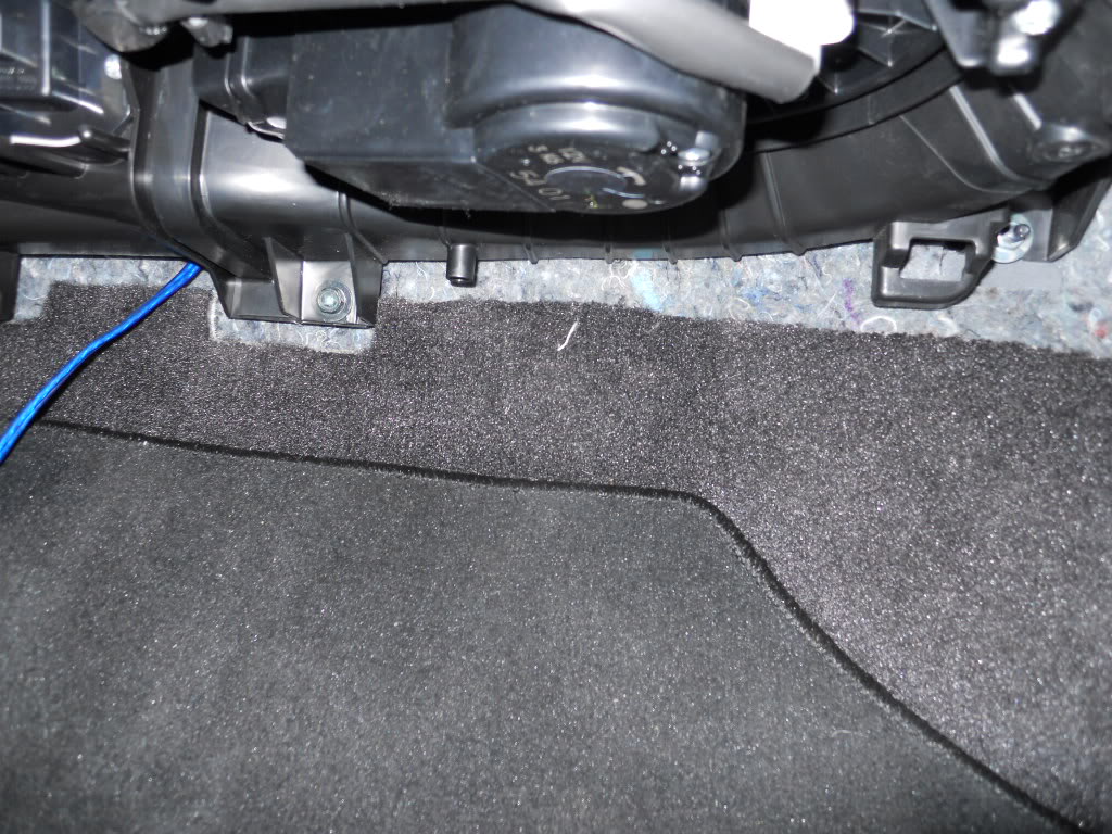
(Above, again, you see the wire already run...but you can see the ductwork as well.)
2. Remove the grommet pictured above. Just pull on it, and it will pop out of the firewall. Use the awl to poke a hole in the grommet, and push your wires through it (remember, two wires!). Pull a couple feet of wire through the grommet, then push that wire through the firewall into the cabin. Make sure the wire goes over insulation.
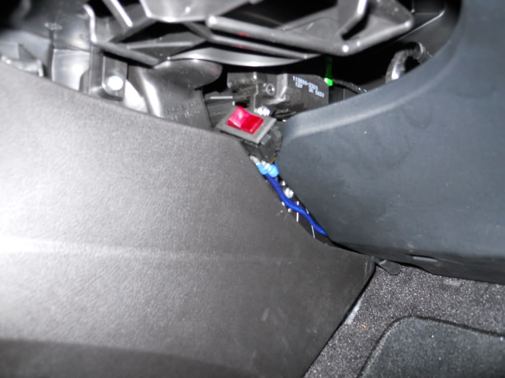
3. Head back into the interior, and pull the wire down from behind the ducts. This may take some work, as there's not much space to work in. Once you've got the wires through, wire up the switch and mount it somewhere. Mine isn�t �mounted� yet, but this is where it�ll be. Bolt the ducts back down, and reinstall the cover.
4. Heading back to the engine compartment, reinstall the grommet in the firewall. It should just pop back into its hole with some force; make sure it�s properly seated!
5. Mount the relay. There is an engine ground cable bolted to the passenger inner fender near the windshield washer fluid fill. I used this as my relay mount, and as my ground for the relay as well (terminal 86). I'm going to clean this up later with black electrical tape. You'll want to cover all of the metal on the relay so it doesn't corrode (liquid electrical tape should work well here).
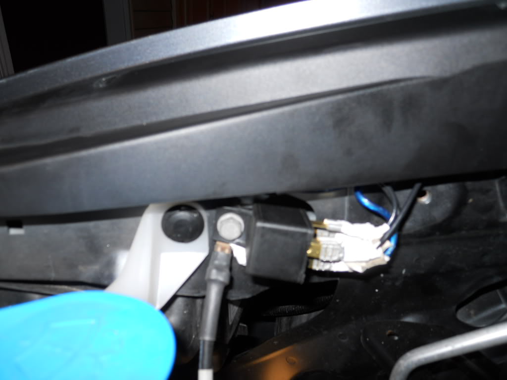
6. Run a wire from the battery positive terminal to terminal 30 on the relay. Be sure to use that fused link you bought, within 18� of the battery.
7. Connect the relay to the foglights. Stock, each foglight is powered by its own circuit; a 10A fuse can be found both in the driver's side fuse box and the passenger's side fuse box. As such, you�ll need to run power from the relay to both fog lights, not just one. I found it easiest to jack the car up for some extra room, but you should be able to get by w/o doing so.
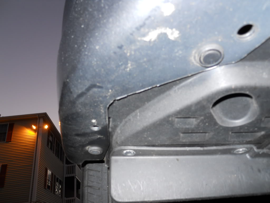
On the underside of the front bumper, you�ll need to remove three body fasteners near each corner. You can see two in the pic below; the third one is a little more towards the center of the car. Use a small flathead screwdriver to pop the center (male end) of these fasteners out, then pull the female end out (sometimes they come out together). Once all three are out on a side, just use some force to get the plastic cover out of the way.
Unplug the fog light wires from the bulb, and remove the electrical tape from the wires near the plug. Find the positive wire (it�s the one that�s NOT black), and splice into it with another wire. Now run that new wire up into the engine compartment, and connect it to terminal 87 on the new relay (there will be two 87s). Tape up the wires again, plug the connector back into the fog light, and replace the plastic cover and fasteners. Do the same thing for the other fog light, and connect that new wire to the other terminal 87.
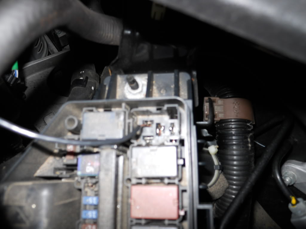
8. Switching the relay. You can use whatever �switch� you want for the relay depending on how you want the lights to function, but I chose to use something that gets power only when the key is in ON. This way I don�t have to remember to turn the lights off when I leave the car. Head to your underhood fuse box, and remove the relay in the upper right corner (if you�re looking at the box from the driver�s side). I believe that�s the windshield wiper motor relay, but I can�t remember now�it�s depicted below, anyway.
Take another length of new wire, and strip about 1.5� from the end. With the WW relay removed, stick the end of your new wire into the upper left female terminal in the fuse box (shown below). Reinstall the relay, and test that the wire is securely pinned down by the relay.
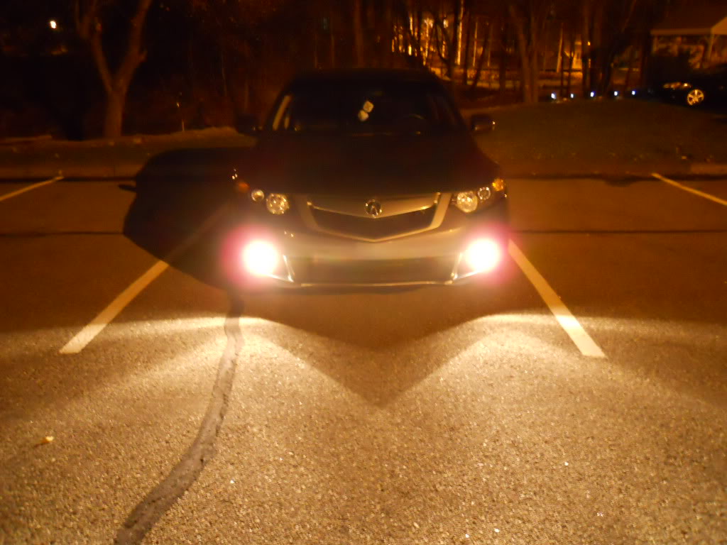
Run that new wire to your newly-installed relay, terminal 85. Turn key to on, and voila:
Tomorrow I'll post the wiring diagrams I have, just need to scan them in.
What you'll need:
Wire strippers/cutters
Utility knife
Electrical tape (black would be best, all I had was white laying around)
Awl (not pictured)
Needlenose pliers
Switch
12v relay (any generic five terminal relay will do)
Fuseable link and 10A fuse
Flathead screwdriver
Wire
I wanted to maintain the ability to switch the fogs off if I wanted, so I hid the switch inside the cabin above the passenger's feet. You could put the switch anywhere of course; this was the easiest spot for me right now. If you look at the engine compartment side of the firewall, you'll see two rubber grommets with one bundle of wires going through each. The one near the center of the car was too difficult for me to get to in the interior, so I chose to use the grommet on passenger side.
Above you see my new wires already running through the grommet. Here's how I did it:
1. Remove the panel above the passenger footwell. You'll see a lot of plastic ductwork. Remove the center screw at the bottom of this ductwork, as well as the nut on the right side bottom. This should allow you to move the ducts a little bit. You'll need to stick your hand behind the ducts to route the wires.
(Above, again, you see the wire already run...but you can see the ductwork as well.)
2. Remove the grommet pictured above. Just pull on it, and it will pop out of the firewall. Use the awl to poke a hole in the grommet, and push your wires through it (remember, two wires!). Pull a couple feet of wire through the grommet, then push that wire through the firewall into the cabin. Make sure the wire goes over insulation.
3. Head back into the interior, and pull the wire down from behind the ducts. This may take some work, as there's not much space to work in. Once you've got the wires through, wire up the switch and mount it somewhere. Mine isn�t �mounted� yet, but this is where it�ll be. Bolt the ducts back down, and reinstall the cover.
4. Heading back to the engine compartment, reinstall the grommet in the firewall. It should just pop back into its hole with some force; make sure it�s properly seated!
5. Mount the relay. There is an engine ground cable bolted to the passenger inner fender near the windshield washer fluid fill. I used this as my relay mount, and as my ground for the relay as well (terminal 86). I'm going to clean this up later with black electrical tape. You'll want to cover all of the metal on the relay so it doesn't corrode (liquid electrical tape should work well here).
6. Run a wire from the battery positive terminal to terminal 30 on the relay. Be sure to use that fused link you bought, within 18� of the battery.
7. Connect the relay to the foglights. Stock, each foglight is powered by its own circuit; a 10A fuse can be found both in the driver's side fuse box and the passenger's side fuse box. As such, you�ll need to run power from the relay to both fog lights, not just one. I found it easiest to jack the car up for some extra room, but you should be able to get by w/o doing so.
On the underside of the front bumper, you�ll need to remove three body fasteners near each corner. You can see two in the pic below; the third one is a little more towards the center of the car. Use a small flathead screwdriver to pop the center (male end) of these fasteners out, then pull the female end out (sometimes they come out together). Once all three are out on a side, just use some force to get the plastic cover out of the way.
Unplug the fog light wires from the bulb, and remove the electrical tape from the wires near the plug. Find the positive wire (it�s the one that�s NOT black), and splice into it with another wire. Now run that new wire up into the engine compartment, and connect it to terminal 87 on the new relay (there will be two 87s). Tape up the wires again, plug the connector back into the fog light, and replace the plastic cover and fasteners. Do the same thing for the other fog light, and connect that new wire to the other terminal 87.
8. Switching the relay. You can use whatever �switch� you want for the relay depending on how you want the lights to function, but I chose to use something that gets power only when the key is in ON. This way I don�t have to remember to turn the lights off when I leave the car. Head to your underhood fuse box, and remove the relay in the upper right corner (if you�re looking at the box from the driver�s side). I believe that�s the windshield wiper motor relay, but I can�t remember now�it�s depicted below, anyway.
Take another length of new wire, and strip about 1.5� from the end. With the WW relay removed, stick the end of your new wire into the upper left female terminal in the fuse box (shown below). Reinstall the relay, and test that the wire is securely pinned down by the relay.
Run that new wire to your newly-installed relay, terminal 85. Turn key to on, and voila:
Tomorrow I'll post the wiring diagrams I have, just need to scan them in.

The following users liked this post:
BLKOUT714 (01-30-2012)
11-14-2010, 09:53 PM
#2
Drifting
fucking awesome man!!
how did you figure it out?
ill try this.
whats awl?
what wire gauge did you use?
how long did it take?
how did you figure it out?
ill try this.
whats awl?
what wire gauge did you use?
how long did it take?
Last edited by defconskylude; 11-14-2010 at 10:05 PM.
11-14-2010, 10:53 PM
#3
Drifting
did you unplug your battery while doing this?
can you post a picture of the postive wire from the battery? do you just splice into the positive battery terminal? how would you do this?
how can you tell whats terminal 30 on the relay? does it say terminal 30 on the relay?
how does your fusable link look like? are these just a bunch of male and female end connectors hooked up to a wire?
so theres only 1 positive wire that will be spliced into each foglight wires that runs individually to terminal 87 on the relay?
so do we need 2 relays? one for passenger side and one for driver side for each foglight? no right?
11-15-2010, 01:35 AM
#5
Three Wheelin'
Nice job.
You can get a light switch/button from a Honda dealer that you can install next to the VSA button. I have seen one in the current gen USDM Accord with blue ambient light and they have a separate light switch/button very similar to our VSA button.
You can get a light switch/button from a Honda dealer that you can install next to the VSA button. I have seen one in the current gen USDM Accord with blue ambient light and they have a separate light switch/button very similar to our VSA button.
11-15-2010, 07:23 PM
#6
Instructor
Is it possible to tweak the fog light wiring to be able to turn on even with just the park lights and DRL on and not only for the headlights? This is what I would want to do to mine :-)
Last edited by BlacK_HawK10; 11-15-2010 at 07:25 PM.
11-15-2010, 09:39 PM
#7
Gets bored easily
Thread Starter
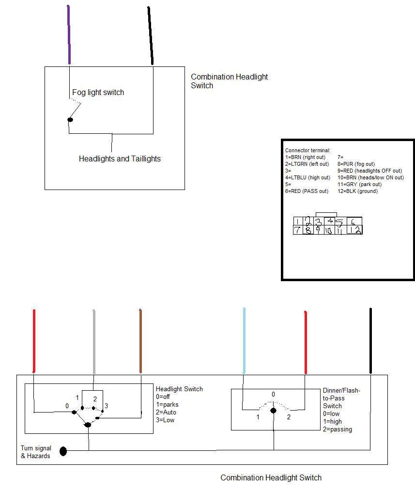
Here's a link to the actual wiring diagrams - click here.
Considering they're not really clear, you can use this BMP too
No. There are two 87 terminals on the relay; I ran a separate wire from each 87 terminal to each fog light positive wire. You could, in theory, run both wires from just one 87 terminal and leave the other empty...but I didn't see the need to do that.
I thought about that, as I would like the ability to easily switch them off if I needed to for some reason...then I found out those switches are like $25. I don't need the ability that badly 
The instructions above allow you to have the fog lights on with any combination of DRLs/parks/lows/highs. Or am I misreading your question? (Also, does your s/n have anything to do with the helicopter?)
Considering they're not really clear, you can use this BMP too
how did you figure it out?
I figured out that I couldn't use the stock switch alone (1) by studying the wiring diagrams and (2) by talking to an Acura tech friend of mine. I figured out how to do the rest just based on my previous automotive knowledge.
ill try this.
whats awl?

what wire gauge did you use?
I think it was 14. The stock wiring is very small, so whatever you have should be fine.
how long did it take?
Maybe 2.5 hours. The hardest part was getting the wires through the firewall (and trying to figure out where to route them first!). If I did it on another car, I could probably shave 60-90 minutes off.
I figured out that I couldn't use the stock switch alone (1) by studying the wiring diagrams and (2) by talking to an Acura tech friend of mine. I figured out how to do the rest just based on my previous automotive knowledge.
ill try this.
whats awl?
what wire gauge did you use?
I think it was 14. The stock wiring is very small, so whatever you have should be fine.
how long did it take?
Maybe 2.5 hours. The hardest part was getting the wires through the firewall (and trying to figure out where to route them first!). If I did it on another car, I could probably shave 60-90 minutes off.
did you unplug your battery while doing this?
No, but that's not a bad idea anytime you're working with electronics.
can you post a picture of the postive wire from the battery? do you just splice into the positive battery terminal? how would you do this?
I can post up a pic if you want...but what I did was, attach a Y terminal to the end of the fused link , loosen the positive battery terminal clamp's nut a little bit, and slip the Y connector between the nut and the clamp. Then tighten back up. Do NOT try to splice into the battery cable!

how can you tell whats terminal 30 on the relay? does it say terminal 30 on the relay?
It says it on the relay, and the packaging should say it as well.
how does your fusable link look like? are these just a bunch of male and female end connectors hooked up to a wire?
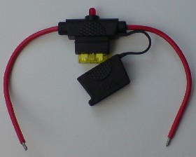
It was pictured in the first pic above, but a similar one is below.
so theres only 1 positive wire that will be spliced into each foglight wires that runs individually to terminal 87 on the relay?
Yes
so do we need 2 relays? one for passenger side and one for driver side for each foglight? no right?
No, but that's not a bad idea anytime you're working with electronics.
can you post a picture of the postive wire from the battery? do you just splice into the positive battery terminal? how would you do this?
I can post up a pic if you want...but what I did was, attach a Y terminal to the end of the fused link , loosen the positive battery terminal clamp's nut a little bit, and slip the Y connector between the nut and the clamp. Then tighten back up. Do NOT try to splice into the battery cable!
how can you tell whats terminal 30 on the relay? does it say terminal 30 on the relay?
It says it on the relay, and the packaging should say it as well.
how does your fusable link look like? are these just a bunch of male and female end connectors hooked up to a wire?
It was pictured in the first pic above, but a similar one is below.
so theres only 1 positive wire that will be spliced into each foglight wires that runs individually to terminal 87 on the relay?
Yes
so do we need 2 relays? one for passenger side and one for driver side for each foglight? no right?
The instructions above allow you to have the fog lights on with any combination of DRLs/parks/lows/highs. Or am I misreading your question? (Also, does your s/n have anything to do with the helicopter?)
Trending Topics
11-15-2010, 10:06 PM
#8
Drifting
i cant really understand your wiring diagram. do you have a simpler version like in layman?
i can draw one up in photoshop and feel free to correct me.
on your switch, there's three prongs. whats connected to that? positive(red), negative(black), and whats the 3rd one?
i can draw one up in photoshop and feel free to correct me.
on your switch, there's three prongs. whats connected to that? positive(red), negative(black), and whats the 3rd one?
Last edited by defconskylude; 11-15-2010 at 10:19 PM.
11-15-2010, 10:15 PM
#9
Gets bored easily
Thread Starter
The wiring diagram was posted for informational purposes only - you don't need to understand it to follow my DIY...in fact, the diagram isn't related to completing the mod at all. I only posted it because I got the information locally, and wasn't able to find it online before.
The number of terminals on a switch will differ depending on the type of switch. I happened to have handy a switch that lights up when it's on...its third terminal needs to be connected to ground for it to light up. I didn't actually want it to light up, so I didn't ground out the third terminal. If you buy a switch that doesn't light up, it will only have two terminals.
The number of terminals on a switch will differ depending on the type of switch. I happened to have handy a switch that lights up when it's on...its third terminal needs to be connected to ground for it to light up. I didn't actually want it to light up, so I didn't ground out the third terminal. If you buy a switch that doesn't light up, it will only have two terminals.
11-15-2010, 11:01 PM
#10
Drifting
where does the red wire and green wire on the switch connect to which part of the relay?
do i just splice the positive wire from the switch to either terminal 87 or 30 on the relay?
am i missing anything else?

do i just splice the positive wire from the switch to either terminal 87 or 30 on the relay?
am i missing anything else?
Last edited by defconskylude; 11-15-2010 at 11:05 PM.
11-15-2010, 11:01 PM
#11
Drifting
The wiring diagram was posted for informational purposes only - you don't need to understand it to follow my DIY...in fact, the diagram isn't related to completing the mod at all. I only posted it because I got the information locally, and wasn't able to find it online before.
The number of terminals on a switch will differ depending on the type of switch. I happened to have handy a switch that lights up when it's on...its third terminal needs to be connected to ground for it to light up. I didn't actually want it to light up, so I didn't ground out the third terminal. If you buy a switch that doesn't light up, it will only have two terminals.
The number of terminals on a switch will differ depending on the type of switch. I happened to have handy a switch that lights up when it's on...its third terminal needs to be connected to ground for it to light up. I didn't actually want it to light up, so I didn't ground out the third terminal. If you buy a switch that doesn't light up, it will only have two terminals.
11-16-2010, 08:33 PM
#12
Drifting
whats the male and female connector size do we use with the relay and switch?
also i got a 20amp fuse holder? would a 10amp fuse be ok to load in there? i couldnt find a 10amp fuse holder
the fuse holder has 12 gauge wires. would a 16 gauge wire be ok to connect with the 12 gauge?
also i got a 20amp fuse holder? would a 10amp fuse be ok to load in there? i couldnt find a 10amp fuse holder
the fuse holder has 12 gauge wires. would a 16 gauge wire be ok to connect with the 12 gauge?
Last edited by defconskylude; 11-16-2010 at 08:46 PM.
11-16-2010, 09:31 PM
#13
Gets bored easily
Thread Starter
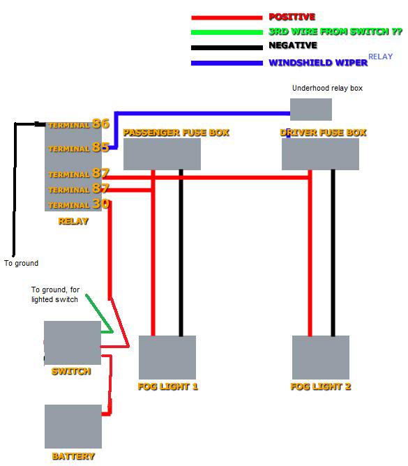
Here you go - your diagram was slightly off.
whats the male and female connector size do we use with the relay and switch?
The male/female ends are only one size. The only thing that differs size-wise is the end where you crimp the wire...and you need whatever size terminal fits on the wire you're using.
also i got a 20amp fuse holder? would a 10amp fuse be ok to load in there? i couldnt find a 10amp fuse holder
You can put any size fuse in there. Start with a 10A fuse, and if it blows, put a 20A fuse in there.
the fuse holder has 12 gauge wires. would a 16 gauge wire be ok to connect with the 12 gauge?
Yup
11-16-2010, 10:03 PM
#14
Drifting
ok i understand the 2 grounds for the switch and terminal 86.
im confused in your edited diagram in regards to the positive wires on the switch and battery. 1) you show that terminal 30 is connected to the switch, and 2) the switch is connected to the battery? in your guide, you said to use the fused link between the battery to terminal 30. can you expand on this?
where does the positive wire of the switch connect to?
11-16-2010, 10:12 PM
#15
Gets bored easily
Thread Starter
Yes, if you want to have the ability to switch the lights off, you need to put the switch in the middle of the power wire (or in the middle of the "switched" wire, the one from the windshield wiper relay). Think of it this way - any switch serves to interrupt the flow of electricity, or complete the flow. If you put the switch off the normal flow of that electricity (instead of inline with the flow), the switch won't actually switch anything!
The fuse should be within 18" of the battery. It's not depicted on your drawing, but it would be right next to the battery, between it and the switch.
The two terminals on my switch which were not the ground wire connected (1) to the battery (fused link) and (2) to Terminal 30 on the relay...just as shown in the diagram. If you get a non-lighted switch, it will only have two terminals, so you won't have any confusion.
11-16-2010, 10:20 PM
#16
Drifting
the edit diagram threw me off because the switch is in the engine? i thought it would be inside the interior?
more likely i wont turn off my foglights. i just want them on at all times after turning the key.
let me edit the diagram with the fused link
more likely i wont turn off my foglights. i just want them on at all times after turning the key.
let me edit the diagram with the fused link
11-16-2010, 10:22 PM
#17
Gets bored easily
Thread Starter
The edited diagram doesn't really show that, b/c the fuse boxes are in the passenger compartment as well. If you'd like, draw a half circle around the switch like this ) to show that it's separate from the engine bay.
 11-23-2010, 07:44 PM
#21
Gets bored easily
Thread Starter
If you connect the #85 terminal on the relay to something that only gets power when the key is ON, then accidentally leaving the fogs on is impossible.
11-24-2010, 08:12 AM
#22
Racer
If you wire in a switch like I did, and you turn the new switch OFF, the stock fog light switch works as designed. If the new switch is ON, however, you're bypassing the stock switch.
If you connect the #85 terminal on the relay to something that only gets power when the key is ON, then accidentally leaving the fogs on is impossible.
If you connect the #85 terminal on the relay to something that only gets power when the key is ON, then accidentally leaving the fogs on is impossible.
11-24-2010, 09:22 AM
#24
Racer
wanna come down to philly and help me out with this?
dinner on me haha
im still having trouble figuring out the wiring of this. where these components get wired too
dinner on me haha
im still having trouble figuring out the wiring of this. where these components get wired too
11-24-2010, 12:44 PM
#26
Racer
ok, i studied the page.
so the WW relay connection is used to give power to the new relay. this relay will the only power on the fog lights when the battery is connected (through the new switch) and when terminal 85 is getting power from the WW relay. this provides the off function for when the car is not on prevent accidental battery drain.
What i wanted to do was keep the stock switch but allow the headlights to be turned on with the parking lights. and i think with a tweak to your setup it is possible.
remove the switch from your diagram and have the battery connected directly to the relay through the new fuse.
then terminal 85, instead of being connected to the WW relay, connect it to one of the parking light positive wires, right before the bulb. this way terminal 85 will receive power once the parking lights are turn on, thus turning on the fog lights.
what do you think?
props on your research. i think i might keep the switch in play just for the added functionality. i just hope i can make everything look clean, from the switch, to mounting the relay and fuse, and the wiring.
where can i find that honda switch to put next to the vsa. but i could always drill out one of the blanks and place one in there.
thanks again for the write up. i plan on doing this sometime.
11-26-2010, 12:19 PM
#27
Gets bored easily
Thread Starter
hjahmad - connecting #85 directly to the parking light hot wire will be fine if you want the lights to be on only when the parks are. I wanted the ability to have the fogs on independent of the parks, so I used a different "switch" for #85.
12-01-2010, 03:54 PM
#28
Drifting
i tried doing this yesterday and messed up. i bought a $17 kit off pepboys that supplied the 5 pin relay, switch, and 7 wires with the end connectors.
1) wires in the kit were too short. i have to make longer wires and end connectors from scratch
2) end connector for the WW fuse was too big. i realized you're using a smaller end connector to plug into the WW fuse and when you plug the WW relay over the end connector, it wont have any problems going down.
3) it got dark and i couldnt find my damn flashlight
the good part was i actually hooked up all the wires correctly to the relay and switch. so visually i have a better understanding now.
another question:
the 5 pin relay i have is for a 30amp. is this ok even though i have a 10amp fuse and a 20amp fuse holder?
ill tackle this over the weekend and make a video of the installation
Last edited by defconskylude; 12-01-2010 at 04:06 PM.
12-01-2010, 07:09 PM
#29
Gets bored easily
Thread Starter
That's why prepacked stuff, unless specifically for your car, is always a PITA 
Glad you got the ball rolling - hopefully the wrap-up goes well this weekend. To answer your question, yes that should be fine. The really is really just there to act as a switch; the 10A fuse will be the thing that blows first, anything larger (30A) downstream of there shouldn't ever pop. And you can use any amperage fuse in any fuse holder, so long as it's the right shape fuse.
Glad you got the ball rolling - hopefully the wrap-up goes well this weekend. To answer your question, yes that should be fine. The really is really just there to act as a switch; the 10A fuse will be the thing that blows first, anything larger (30A) downstream of there shouldn't ever pop. And you can use any amperage fuse in any fuse holder, so long as it's the right shape fuse.
12-01-2010, 09:36 PM
#31
Gets bored easily
Thread Starter
Originally Posted by me, above
how long did it take?
Maybe 2.5 hours. The hardest part was getting the wires through the firewall (and trying to figure out where to route them first!). If I did it on another car, I could probably shave 60-90 minutes off.
Maybe 2.5 hours. The hardest part was getting the wires through the firewall (and trying to figure out where to route them first!). If I did it on another car, I could probably shave 60-90 minutes off.
02-20-2011, 08:35 PM
#33
Drifting
ive attempted this and im about 90% done.
the male connector to the relay was too big.
what other alternatives can i use instead of the windshield wiper relay?
i have a 3 prong switch
the male connector to the relay was too big.
what other alternatives can i use instead of the windshield wiper relay?
i have a 3 prong switch
Last edited by defconskylude; 02-20-2011 at 08:38 PM.
02-20-2011, 08:57 PM
#34
Gets bored easily
Thread Starter
You are confusing the two relays in my instructions. The relay in Step 5 is essentially a fancy fuse. The relay in Step 8 (the windshield wiper motor relay) is used to "open" the Step 5 Relay so power can reach the fogs.
The fact that you have a 3 prong switch has no bearing on the relay(s) used.
In lieu of the wiper motor relay, you could use any other relay that turns on only when the key is ON or ACC. If you chose to not add a separate relay in Step 5 Relay, you don't need to (and, really, cannot) run a wire from the wiper motor relay. Just run a power wire from the battery, through an add-on fuse, to a switch, to the fogs.
02-20-2011, 09:50 PM
#35
Drifting
Just run a power wire from the battery, through an add-on fuse, to a switch, to the fogs.
so can i just tap a wire from terminal 85 into the wire thats connected to the fuse holder/battery?
or should i get another fuse holder for terminal 85 that connects to the battery?
what happens if i dont use terminal 85 at all?
i skipped the grommet/firewall part. i just lined up the wires to go through the upper passenger hood, and passenger door.
im almost there man!! took me 2 hours so far.
02-20-2011, 10:02 PM
#36
Gets bored easily
Thread Starter
You have to read everything I wrote, not just a portion of it.
All of the bold text goes together. So, if you're adding a "Step 5 Relay" (which it sounds like you already have done, and is really the right thing to do), then you cannot just run a wire from the battery to Terminal 85 on the Step 5 Relay if you want an auto-off feature on the fogs.
In other words: technically you can run a wire from Battery to 85, but if you don't remember to flip your added switch when you shut the car off, the fogs will stay on. If you run a wire from anything that only gets power when the key is in the ON or ACC positions to 85, you will have that "auto-off" feature.
If you don't connect anything to 85, the Step 5 Relay will never get switched on, so all your work will be for nothing.
If you chose to not add a separate relay in Step 5 Relay, you don't need to (and, really, cannot) run a wire from the wiper motor relay. Just run a power wire from the battery, through an add-on fuse, to a switch, to the fogs.
In other words: technically you can run a wire from Battery to 85, but if you don't remember to flip your added switch when you shut the car off, the fogs will stay on. If you run a wire from anything that only gets power when the key is in the ON or ACC positions to 85, you will have that "auto-off" feature.
If you don't connect anything to 85, the Step 5 Relay will never get switched on, so all your work will be for nothing.
02-20-2011, 10:23 PM
#37
Drifting
Just run a power wire from the battery, through an add-on fuse, to a switch, to the fogs.
yes i have a step 5 relay just like yours.
87 and 87a are wired to the positive wires on the fogs
30 wired to switch
86 is grounded
85 still empty
battery/fuse holder wired to switch
ground wired to switch
yea i really do want to get power when they key is ON or ACC.
i was using this diagram to wire it up

Last edited by defconskylude; 02-20-2011 at 10:25 PM.
02-20-2011, 10:54 PM
#39
Drifting
also on my 3 prong switch, theres 2 silver and 1 gold. you mentioned the middle one is for the power switch that connects to the fuse holder/battery
what about the other gold and silver prong left over? i think the gold one is the ground, while the silver prong connects to terminal 30
what about the other gold and silver prong left over? i think the gold one is the ground, while the silver prong connects to terminal 30
02-21-2011, 07:35 PM
#40
Gets bored easily
Thread Starter
but i already have a power wire from the battery and fuse holer connected on a switch
yes i have a step 5 relay just like yours.
87 and 87a are wired to the positive wires on the fogs
30 wired to switch
86 is grounded
85 still empty
battery/fuse holder wired to switch
ground wired to switch
yea i really do want to get power when they key is ON or ACC.
yes i have a step 5 relay just like yours.
87 and 87a are wired to the positive wires on the fogs
30 wired to switch
86 is grounded
85 still empty
battery/fuse holder wired to switch
ground wired to switch
yea i really do want to get power when they key is ON or ACC.
If you want power only when key ON or ACC, then why can't you use the wiper motor relay for 85 like I described?
also on my 3 prong switch, theres 2 silver and 1 gold. you mentioned the middle one is for the power switch that connects to the fuse holder/battery
what about the other gold and silver prong left over? i think the gold one is the ground, while the silver prong connects to terminal 30
what about the other gold and silver prong left over? i think the gold one is the ground, while the silver prong connects to terminal 30
- You do not have to ground your switch. The ground is only for the switch to be illuminated when power is on. If you do want the switch to light up, then you must ground it.
- If you DON'T ground the switch, then it doesn't matter which silver terminal is power in and which is power out. If you DO ground the switch, just try the "in" and "out" wires one way --- if the fog lights come on and the switch light is on, you're good to go. If the fog lights come on and the switch light is off, you have the silver terminals reversed.