Does anyone know where to find the power wire from the dome light switch?
i'll be tapping the puddle lights i got to this so when i open and close the door, the puddle lights will come on along with the interior lights. thanks
i'll be tapping the puddle lights i got to this so when i open and close the door, the puddle lights will come on along with the interior lights. thanks
Being an Acha Bacha in
I tried searching for this the other day and couldn't find any threads. And the threads that I did find, they talked about tapping it but they didn't show which wire they tapped.
yeah the only thing i remember is it being done on a tsx but im assuming the wire is differnt then the tl's... no one knows?
Just got my lights in from Oznium Saturday. Gonna take a voltometer to the rear map lights tomorrow morning. I'll let you know.
Retired!!! ON TOP!!!
I got y'all covered... the dome wire circuit is very trickie... But I'm willing to help you guys out...
What do you want to achieve??? Do you want to hit the remote and when the doors unlock you want the lights to turn ON??? Do you want to turn on the accessories with the dome lights too???
Let me know... then I'll give you the right wire and what to use to wire it up correctly... 'cause I've already did it for my door handles LEDs...
Being an Acha Bacha in
Can you give us both options Rodney? I want to put it on a switch but don't want to add extra switches to my dash, so I'd like to just control it off a pre-existing switch, and I guess the best one is the switch for domes, unless you have a better idea.

Safety Car
I did the puddle light mod awhile back. I used the dome light wires that are located in the a-pillar. If I remember correctly one is gray with a blue stripe and the other is green with red, I think the gray is the + and the green is the -. I remember these 2 wires being thicker then the other wires in the a-pillar.
I have puddle lights wired to the dome lights so they come on/off when you lock/unlock the doors.
I have puddle lights wired to the dome lights so they come on/off when you lock/unlock the doors.
Quote:
What do you want to achieve??? Do you want to hit the remote and when the doors unlock you want the lights to turn ON??? Do you want to turn on the accessories with the dome lights too???
Let me know... then I'll give you the right wire and what to use to wire it up correctly... 'cause I've already did it for my door handles LEDs...
well i wanted the lights to come on when i unlock the doors via the key remote. i also have a switch that came with the puddle lights that lets me change the mode of the lights so im going to wire that in too. Could you tell me which wire and where to find it when hitting the key remote? thanksOriginally Posted by rodneyc77
I got y'all covered... the dome wire circuit is very trickie... But I'm willing to help you guys out... What do you want to achieve??? Do you want to hit the remote and when the doors unlock you want the lights to turn ON??? Do you want to turn on the accessories with the dome lights too???
Let me know... then I'll give you the right wire and what to use to wire it up correctly... 'cause I've already did it for my door handles LEDs...
Quote:
I have puddle lights wired to the dome lights so they come on/off when you lock/unlock the doors.
oh ok thanks. i'll go this route if i cannot have the lights turned out w/o wiring them up to the dome lights if it's possible.Originally Posted by CarrieLynn
I did the puddle light mod awhile back. I used the dome light wires that are located in the a-pillar. If I remember correctly one is gray with a blue stripe and the other is green with red, I think the gray is the + and the green is the -. I remember these 2 wires being thicker then the other wires in the a-pillar.I have puddle lights wired to the dome lights so they come on/off when you lock/unlock the doors.
Safety Car
^ yea i didnt switch mine because the only time i wanted them on was when i locked/inlocked the doors. Anyway lmk how you make out 
Just did my testing. The rear map lights have three wires: Y - GY/BL - W. Yellow did nothing, whether the lights were on or off. It may serve some purpose when you're actually using the map light. Gray/Blue constantly fluctuated. It never made 0 volts nor 12 volts, just back and forward between 3 and 6. The white seems the most promising but it's weird. Sitting in the car with the lights off, it reads a full 12 volts but as soon as you unlock and the lights come on, zero. Like the polarity is reversed some way. Can anyone explain this?
If you could, CarrieLynn, take a picture of the wires you tapped in the A-pillar. I didn't see a G/R wire and the GY/BL I found was the same thickness as the others. Two thickest were black and red, I believe.
InFaMouSLink
Chapter Leader (NY/NJ)
close


Jun 6, 2025
- Join DateOct 2008
- LocationRahway, NJ
- Age41
- Posts:2,596
-
iTrader Positive Feedback100
-
iTrader Feedback Score(10)
-
Likes:121
-
Liked:187 Times in 147 Posts
Quote:
relay where white is actually a ground trigger. you are getting 12V on the meter but its not true power. ( dont quote me i'll look into this later)Originally Posted by ciscopath
Just did my testing. The rear map lights have three wires: Y - GY/BL - W. Yellow did nothing, whether the lights were on or off. It may serve some purpose when you're actually using the map light. Gray/Blue constantly fluctuated. It never made 0 volts nor 12 volts, just back and forward between 3 and 6. The white seems the most promising but it's weird. Sitting in the car with the lights off, it reads a full 12 volts but as soon as you unlock and the lights come on, zero. Like the polarity is reversed some way. Can anyone explain this?
Being an Acha Bacha in
^^ But if you use the white as a trigger wire AL then won't the coil have to be charged all the time, meaning when the lights are actually off? So you would be in fact hooking up the lights to the 87a constant on prong on the relay? Or am I missing something?
Retired!!! ON TOP!!!
Like Carrie mentioned... the courtesy light circuit is controlled by the negative pulse of the GREEN w/ RED stripe wire... That's how I have my door handles wired up...
The Green w/ red stripe wire can be tapped at the fuse box. It's located at the TOP RIGHT corner (back side) of the fuse box. It's the Last six pin connector (green) on the back side of the fuse box... it's a PITA to get to...
In terms of wiring... just hook up the negative wire to the Green w/ red and the possitive to a constant 12V (B+) source... and you're done... make sure to isolate your NEW circuit with the use of diodes etc...
Good LUCK
InFaMouSLink
Chapter Leader (NY/NJ)
close
Jun 6, 2025
- Join DateOct 2008
- LocationRahway, NJ
- Age41
- Posts:2,596
-
iTrader Positive Feedback100
-
iTrader Feedback Score(10)
-
Likes:121
-
Liked:187 Times in 147 Posts
Quote:
Originally Posted by Elegant TYPE S
^^ But if you use the white as a trigger wire AL then won't the coil have to be charged all the time, meaning when the lights are actually off? So you would be in fact hooking up the lights to the 87a constant on prong on the relay? Or am I missing something?
i wasn't saying how to wire it, i was answering the question of "reversed polarity"
Drifting
i wired mine to the rear map lights.. now my puddle lights turn on whenever the map lights are on. So if I turn on the maplights, my puddle lights turn on.. whenever i lock/unlock my car my map lights/puddle lights turn on.. if i turn off the maplights my maplights/puddle lights/ DO NOT turn on .. i can do all this with the front map light switch.. i remember there being 3 wires coming out of the rear map light.. i just wired my lights into each wire and test it.. took 2 tries to get the wire right.. forgot what color the wires were tho..
Unregistered User
Rodney, did you post a diy on the handle lights? I looked around but I will be a noob at searching forever. Anyway, I have a pretty good idea how to do the mod, but before I start drilling, ha, I'd like to see what options you chose.
Quote:
The Green w/ red stripe wire can be tapped at the fuse box. It's located at the TOP RIGHT corner (back side) of the fuse box. It's the Last six pin connector (green) on the back side of the fuse box... it's a PITA to get to...
In terms of wiring... just hook up the negative wire to the Green w/ red and the possitive to a constant 12V (B+) source... and you're done... make sure to isolate your NEW circuit with the use of diodes etc...
Good LUCK
sorry but do i need to use diodes? and what size/ where do i place them? thanksOriginally Posted by rodneyc77
Like Carrie mentioned... the courtesy light circuit is controlled by the negative pulse of the GREEN w/ RED stripe wire... That's how I have my door handles wired up... The Green w/ red stripe wire can be tapped at the fuse box. It's located at the TOP RIGHT corner (back side) of the fuse box. It's the Last six pin connector (green) on the back side of the fuse box... it's a PITA to get to...
In terms of wiring... just hook up the negative wire to the Green w/ red and the possitive to a constant 12V (B+) source... and you're done... make sure to isolate your NEW circuit with the use of diodes etc...
Good LUCK
and is there a way of checking the codes when your check engine light is on with out using a obd2 scanner? because i remember for my integra, i could use a paper clip, bend it into a U-shape, insert it into the plug and the check engine light would flash either short or long flashes to tell you the number code. then from there, you can look at a list of number codes that stand for certain problems with your car.
Quote:
Thank you, bzyrice. All the testing with the voltometer was confusing, so I went back to the basics: good ol' process of elimination. Originally Posted by bzyrice
i just wired my lights into each wire and test it.. took 2 tries to get the wire right
Positive lead goes to Gray/Blue
Negative lead goes to the White
Oznium lights lit up brilliantly. Can't wait to install them this weekend and check the glow at night. I'll do a DIY on the process when it's all said and done. Thanks again, bzyrice (got it on the 3rd attempt) and those who contributed advice.
Also, I believe I've figured out the "reverse polarity" thing on the white wire is not that at all. The map light and courtesy light "share" either the same power source or ground. The white wire is the constant 12v source for the maps, so when the doors are closed and locked, maps are in control. When unlocked and opened, power is "shifted" from the maps to the courtesy. Which explains more for my testing because whenever I locked the doors, the white wire did not JUMP to 12v, it gradually rose. Makes sense due to the fact that our courtesy lights gradually fade out when locked. Since my TLs a base, gonna wire up and Dremel in two blue leds for each map housing and eliminate the maps as the courtesys but still keep them as, of course, map lights. I'll DIY that one too if no beats me to it.
1st TL-S on air in
Quote:
and is there a way of checking the codes when your check engine light is on with out using a obd2 scanner? because i remember for my integra, i could use a paper clip, bend it into a U-shape, insert it into the plug and the check engine light would flash either short or long flashes to tell you the number code. then from there, you can look at a list of number codes that stand for certain problems with your car.
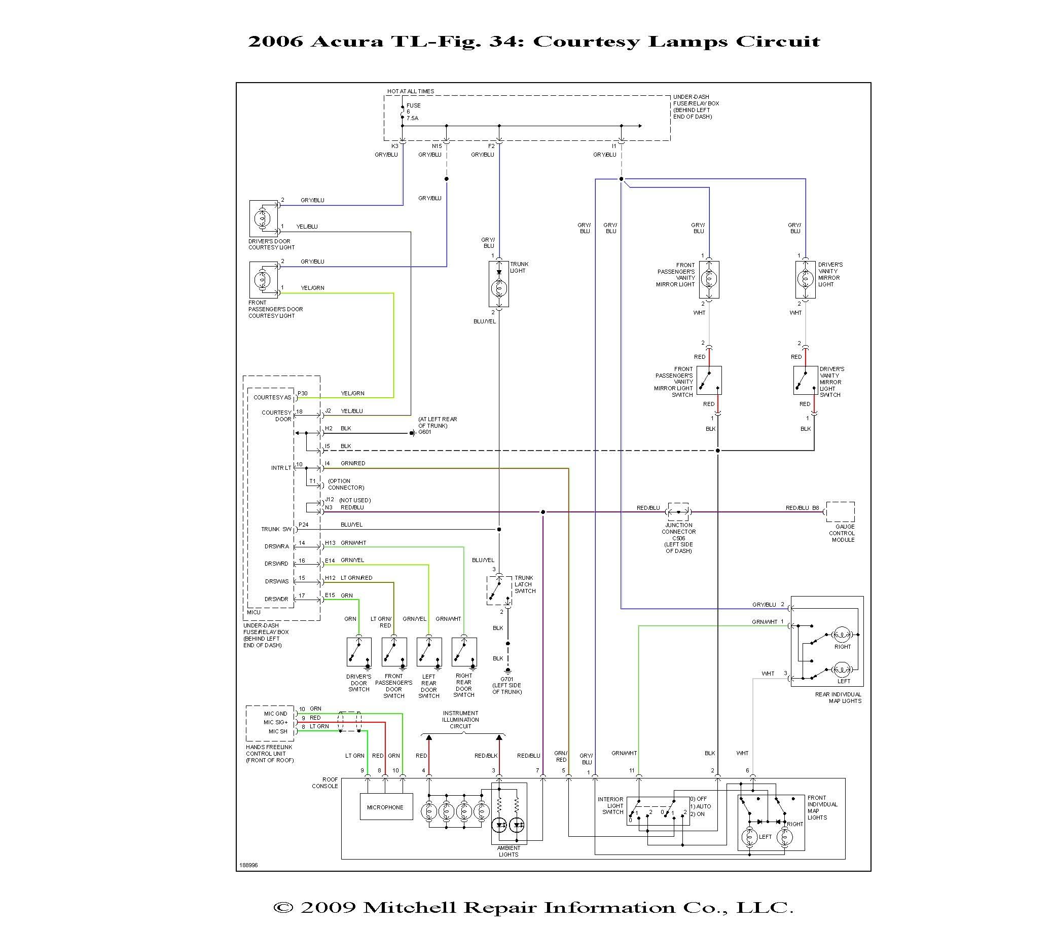
Here is a wiring diagram for the lighting section of your 2006 TL also if you need to check the cel i have a obd2 scanner that can read it for you, just let me know.Originally Posted by nokiaboy808
sorry but do i need to use diodes? and what size/ where do i place them? thanksand is there a way of checking the codes when your check engine light is on with out using a obd2 scanner? because i remember for my integra, i could use a paper clip, bend it into a U-shape, insert it into the plug and the check engine light would flash either short or long flashes to tell you the number code. then from there, you can look at a list of number codes that stand for certain problems with your car.
Drifting
Quote:
Positive lead goes to Gray/Blue
Negative lead goes to the White
Oznium lights lit up brilliantly. Can't wait to install them this weekend and check the glow at night. I'll do a DIY on the process when it's all said and done. Thanks again, bzyrice (got it on the 3rd attempt) and those who contributed advice.
Also, I believe I've figured out the "reverse polarity" thing on the white wire is not that at all. The map light and courtesy light "share" either the same power source or ground. The white wire is the constant 12v source for the maps, so when the doors are closed and locked, maps are in control. When unlocked and opened, power is "shifted" from the maps to the courtesy. Which explains more for my testing because whenever I locked the doors, the white wire did not JUMP to 12v, it gradually rose. Makes sense due to the fact that our courtesy lights gradually fade out when locked. Since my TLs a base, gonna wire up and Dremel in two blue leds for each map housing and eliminate the maps as the courtesys but still keep them as, of course, map lights. I'll DIY that one too if no beats me to it.
no problem man.. i find that sometimes just wiring up lights is easier then using a voltmeter.. because you know exactly what will happen Originally Posted by ciscopath
Thank you, bzyrice. All the testing with the voltometer was confusing, so I went back to the basics: good ol' process of elimination. Positive lead goes to Gray/Blue
Negative lead goes to the White
Oznium lights lit up brilliantly. Can't wait to install them this weekend and check the glow at night. I'll do a DIY on the process when it's all said and done. Thanks again, bzyrice (got it on the 3rd attempt) and those who contributed advice.
Also, I believe I've figured out the "reverse polarity" thing on the white wire is not that at all. The map light and courtesy light "share" either the same power source or ground. The white wire is the constant 12v source for the maps, so when the doors are closed and locked, maps are in control. When unlocked and opened, power is "shifted" from the maps to the courtesy. Which explains more for my testing because whenever I locked the doors, the white wire did not JUMP to 12v, it gradually rose. Makes sense due to the fact that our courtesy lights gradually fade out when locked. Since my TLs a base, gonna wire up and Dremel in two blue leds for each map housing and eliminate the maps as the courtesys but still keep them as, of course, map lights. I'll DIY that one too if no beats me to it.
worse thing that can happen this way is u blow a fuse =)
Quote:
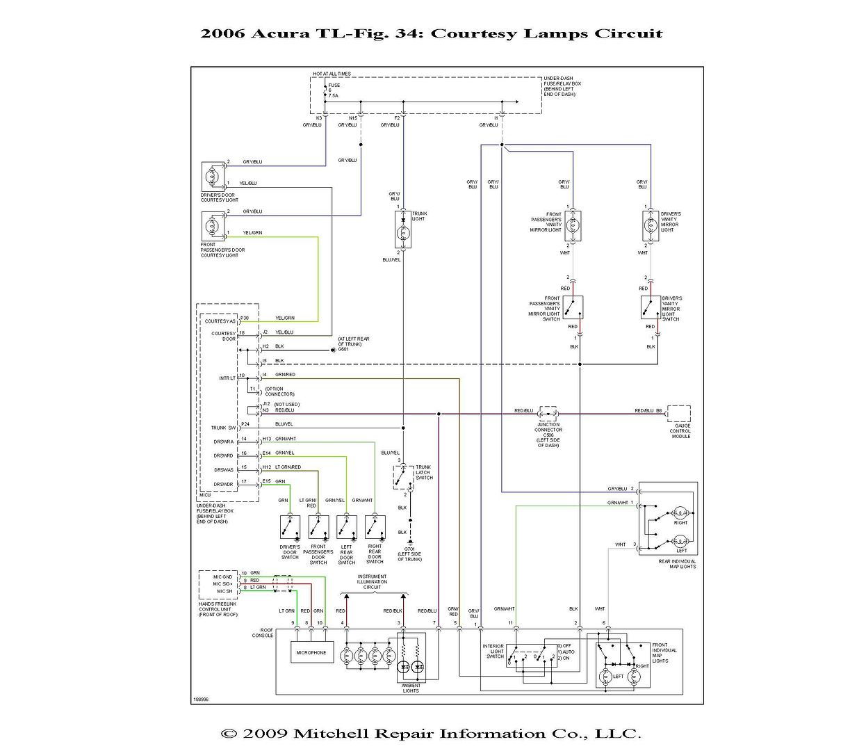
well my check engine light went off.. weird. but thanks anyways and the diagram is pretty useful!Originally Posted by wrxyboy
Here is a wiring diagram for the lighting section of your 2006 TL also if you need to check the cel i have a obd2 scanner that can read it for you, just let me know.
ok so i got a little problem in finding out how to wire up my puddle lights...
heres what i wanted to do.
1) have the puddle lights light up when i unlock/open the door via the interior light green/red wire.
2) be able to use the controller the puddle lights came with. the controller lets you turn your lights off and on and allows you to change the light pattern.
with that said, imagine the controller in the middle. the positive and negative wires to power the switch and lights are located on the top of the switch. the bottom of the switch has the wires that lead to the led puddle lights. there are 2 wires, one for each side of the car and each wire has i think 4 small wires in them.
now my problem is that i would need to tap 2 different sources into just one power/negative wire. how would i do this? would i need to use a relay to have it work or some kind of switch with more than multiple prongs?
i'll post up pictures of the actually puddle lights and controller in a little. thanks in advance!
heres the pictures...
The controller with the positive/negative wires coming from the top and the wires leading to the puddle lights on the bottom of the controller.

Inside the controller. as you can see, the two wires leading to the puddle lights have multiple smaller wires in them. i was going to tap the interior light wires to these but since theres so much wires and their so small, i'm trying to find another way.

The controller with the positive/negative wires coming from the top and the wires leading to the puddle lights on the bottom of the controller.
Inside the controller. as you can see, the two wires leading to the puddle lights have multiple smaller wires in them. i was going to tap the interior light wires to these but since theres so much wires and their so small, i'm trying to find another way.
I hear ya, those small wires can suck especially when using the clamp downs. I invested in Posi-Taps along time ago.

Good luck with a new location.
Good luck with a new location.
1st TL-S on air in
either you can use a on off on toggle switch or you can wire two relays so that one controlls interior lights and one for the controller. Let me know if you need help with this i think i can figure out a solution that would work. Its just easier if i can actually wire it up and work things from there.

I'M GOING IN
Hey guys chime in on helping me out as well I have ozium superflux 12v prewired white LEDs and I cannot get them to turn on I tapped into the front map lights and nothing I am stumpedreally bad I taped into the a pillar were the airbag is also with no luck. Some one chime in I need this project finished please!!!!!!
Quote:
ok id probably want to run the two relays. don't know much about how to wire then up though... pm me your number so you can take a look at it. thanksOriginally Posted by wrxyboy
either you can use a on off on toggle switch or you can wire two relays so that one controlls interior lights and one for the controller. Let me know if you need help with this i think i can figure out a solution that would work. Its just easier if i can actually wire it up and work things from there.
Quote:
Haven't popped the front map assembly to check it's wiring, but I mentioned above the wires to tap in the rear maps.Originally Posted by hondadna4
Hey guys chime in on helping me out as well I have ozium superflux 12v prewired white LEDs and I cannot get them to turn on I tapped into the front map lights and nothing I am stumpedreally bad I taped into the a pillar were the airbag is also with no luck. Some one chime in I need this project finished please!!!!!!
Drifting
Quote:
make sure the lights work.. attach the power and ground wires for your lights to the power and ground of the battery.. if that doesnt work its your lights.. dogh.. you can also figure out which wires do what with your lights.. For example, if you have a black solid wire and a black wire with a white stripe you will most likely figure out the black with white stripe wire is the power wire.. Originally Posted by hondadna4
Hey guys chime in on helping me out as well I have ozium superflux 12v prewired white LEDs and I cannot get them to turn on I tapped into the front map lights and nothing I am stumpedreally bad I taped into the a pillar were the airbag is also with no luck. Some one chime in I need this project finished please!!!!!!
if you test them with the battery and they do work, how are you tapping into the wires in the map lights? Are you using taps or wiring them directly? I hate using the T taps because sometimes you dont get a good connection for some reason. So usually I will just strip the wire I want to get into and then just connect the two wires together.. and if there is enough space I will solder them together.. then just cover up with electric tape..
let us know what happens!
Drifting
Quote:
Positive lead goes to Gray/Blue
Negative lead goes to the White
Oznium lights lit up brilliantly. Can't wait to install them this weekend and check the glow at night. I'll do a DIY on the process when it's all said and done. Thanks again, bzyrice (got it on the 3rd attempt) and those who contributed advice.
Also, I believe I've figured out the "reverse polarity" thing on the white wire is not that at all. The map light and courtesy light "share" either the same power source or ground. The white wire is the constant 12v source for the maps, so when the doors are closed and locked, maps are in control. When unlocked and opened, power is "shifted" from the maps to the courtesy. Which explains more for my testing because whenever I locked the doors, the white wire did not JUMP to 12v, it gradually rose. Makes sense due to the fact that our courtesy lights gradually fade out when locked. Since my TLs a base, gonna wire up and Dremel in two blue leds for each map housing and eliminate the maps as the courtesys but still keep them as, of course, map lights. I'll DIY that one too if no beats me to it.
Originally Posted by ciscopath
Thank you, bzyrice. All the testing with the voltometer was confusing, so I went back to the basics: good ol' process of elimination. Positive lead goes to Gray/Blue
Negative lead goes to the White
Oznium lights lit up brilliantly. Can't wait to install them this weekend and check the glow at night. I'll do a DIY on the process when it's all said and done. Thanks again, bzyrice (got it on the 3rd attempt) and those who contributed advice.
Also, I believe I've figured out the "reverse polarity" thing on the white wire is not that at all. The map light and courtesy light "share" either the same power source or ground. The white wire is the constant 12v source for the maps, so when the doors are closed and locked, maps are in control. When unlocked and opened, power is "shifted" from the maps to the courtesy. Which explains more for my testing because whenever I locked the doors, the white wire did not JUMP to 12v, it gradually rose. Makes sense due to the fact that our courtesy lights gradually fade out when locked. Since my TLs a base, gonna wire up and Dremel in two blue leds for each map housing and eliminate the maps as the courtesys but still keep them as, of course, map lights. I'll DIY that one too if no beats me to it.
Did you ever install those puddle lights?
For all those who are wanting to install the puddle lights I really would suggest doing it through the rear map lights, just because you can remove the rear bottom seat portion and find 2 plugs that lead to the outside of the car making it very easy to wire your puddle lights to your car. Look at the first page of my thread (post #26 - near the bottom of the first page) and I took pics during the whole process.. I also give a little bit of a DIY ..
Click here to see how I did my puddle lights! Pics Included of my install
Oh yah here is a video of my car of how the puddle lights fade in and out with your car alarm .. SOO AWESOME..
http://www.youtube.com/watch?v=EjsyLOIQJIQ
Got "volunteered" to help my wife's brother move Saturday, so that shot the weekend to heck. They'll be on soon
Drifting
Quote:
that sux.. but check out my thread before you start.. it may help out Originally Posted by ciscopath
Got "volunteered" to help my wife's brother move Saturday, so that shot the weekend to heck. They'll be on soon
