
G-100: DIY LED Interior Conversion, Part I: Map Light Console

Thread Starter
Fearless DIY Guy
iTrader: (2)
Joined: Jan 2008
Posts: 3,003
Likes: 376
From: Jersey 'Burbs
G-100: DIY LED Interior Conversion, Part I: Map Light Console
Alright, fellow AZiners...lemme ask you a question...do you LOVE your TL but HATE the crappy GM-esque green glow that illuminates the buttons? I do. SO, there's the obvious action that must be taken and it is a full-on assault against the OE bulbs that Acura provided!
This is the first thread of a multiple thread series that will walk us through the complete LED version for our cars.
Thanks go to dwb993 for specifying the exact bulbs to use.
LET'S GO!
TOOLS NEEDED
Dremel
Soldering Iron
Angle cutters
Flat head screwdriver
T10 Torx Driver
MATERIALS
5 x 3mm bulbs to your liking...I am used wide-angle flat headed 3mm bulbs
Solder
FLUX, I CANNOT STRESS THIS ENOUGH
5 x 560-ohm resistors
Desoldering Braid
TIME
This portion can be fully completed in under 60 minutes
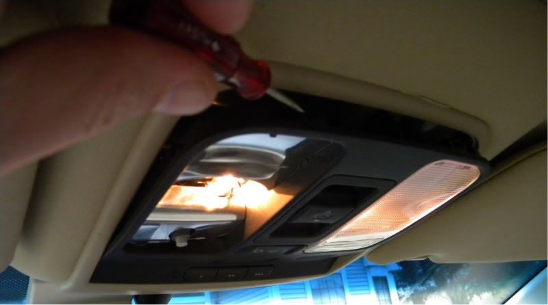
STEP I - MAPLIGHT THIEVERY
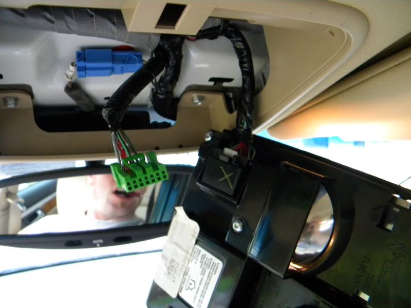
Easy enough, huh? Simply place the screwdriver in between the trim housing and pry towards the windshield. You will need to remove two harnesses by depressing the tab on the male end of the receptacle and pulling out.
STEP II - CRACK OPEN AN AMBIENT TEMPERATURE ONE
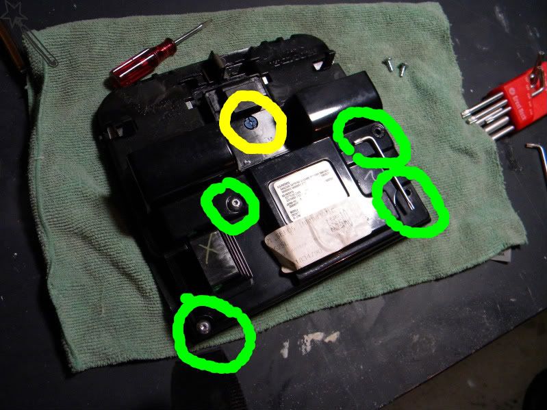
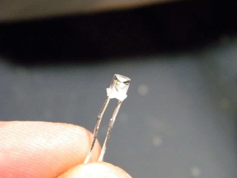
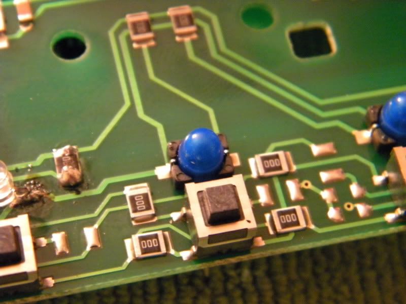
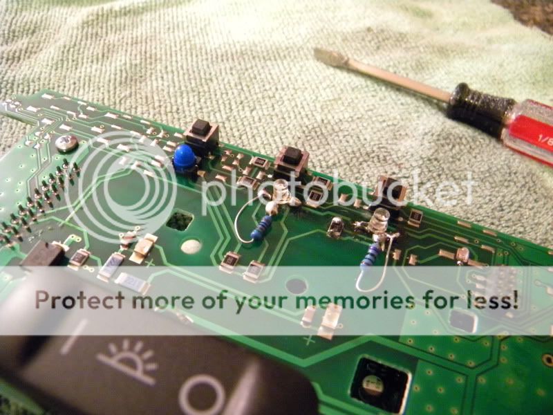
Ok, so what do we have...well, we have our first target with the blue bayonet-style base in front of us and the 4 torx screws to remove. The torx screws are noted in yellow, the bulb, ecto-cooler green. The bayonet style base comes out by turning counter-clockwise to loosen, then pull out.
STEP III - SHAVE AND A HAIRCUT
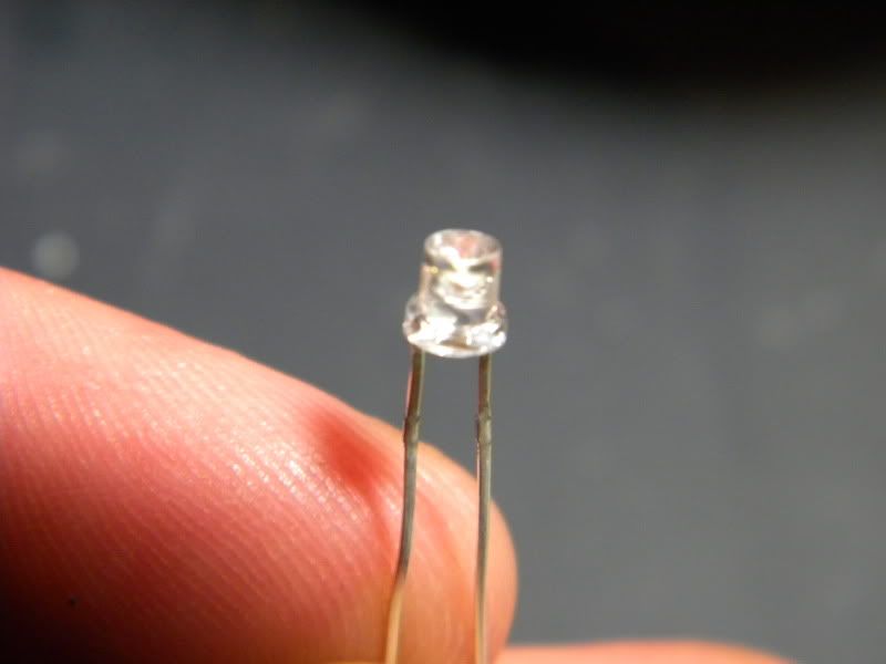
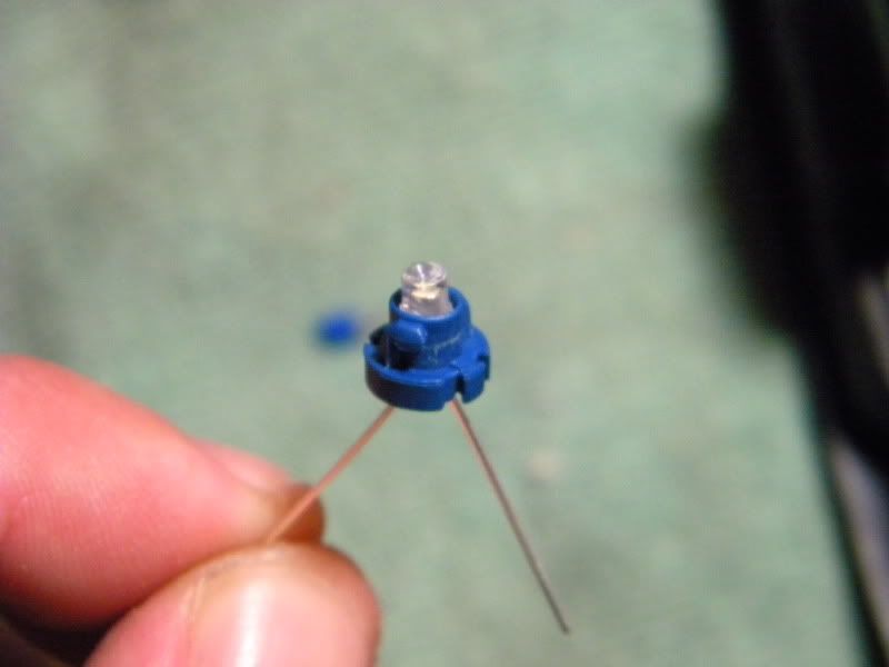
After test fitting one of the LEDs I found that, well, while the bulb fits well enough, I can get it in a bit deeper (heh-heh) if I shave the base of the LED using the dremel, so fire it up and shave away. It's just acrylic, but dusty, so don't do this indoors unless you have some weird fetish for microscopic plastic particulate being strewn throughout your abode.
This is the first thread of a multiple thread series that will walk us through the complete LED version for our cars.
Thanks go to dwb993 for specifying the exact bulbs to use.
LET'S GO!
TOOLS NEEDED
Dremel
Soldering Iron
Angle cutters
Flat head screwdriver
T10 Torx Driver
MATERIALS
5 x 3mm bulbs to your liking...I am used wide-angle flat headed 3mm bulbs
Solder
FLUX, I CANNOT STRESS THIS ENOUGH
5 x 560-ohm resistors
Desoldering Braid
TIME
This portion can be fully completed in under 60 minutes
STEP I - MAPLIGHT THIEVERY
Easy enough, huh? Simply place the screwdriver in between the trim housing and pry towards the windshield. You will need to remove two harnesses by depressing the tab on the male end of the receptacle and pulling out.
STEP II - CRACK OPEN AN AMBIENT TEMPERATURE ONE
Ok, so what do we have...well, we have our first target with the blue bayonet-style base in front of us and the 4 torx screws to remove. The torx screws are noted in yellow, the bulb, ecto-cooler green. The bayonet style base comes out by turning counter-clockwise to loosen, then pull out.
STEP III - SHAVE AND A HAIRCUT
After test fitting one of the LEDs I found that, well, while the bulb fits well enough, I can get it in a bit deeper (heh-heh) if I shave the base of the LED using the dremel, so fire it up and shave away. It's just acrylic, but dusty, so don't do this indoors unless you have some weird fetish for microscopic plastic particulate being strewn throughout your abode.
Last edited by DeathMetal; Oct 1, 2009 at 10:48 PM.
Thread Starter
Fearless DIY Guy
iTrader: (2)
Joined: Jan 2008
Posts: 3,003
Likes: 376
From: Jersey 'Burbs
STEP IV - GET DOWN & SPREAD 'EM
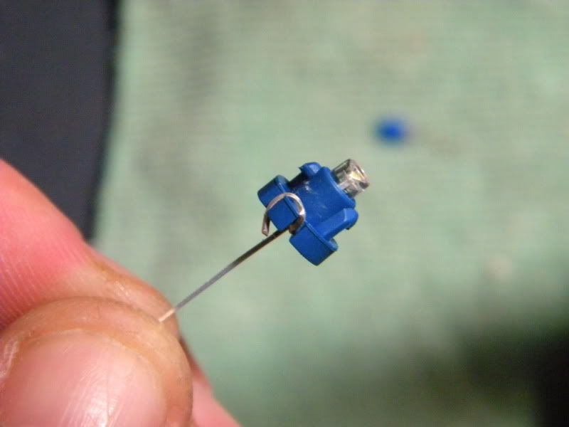
Ok, run the two legs of the LED through the base and spread the LED legs apart. Wrap the longer end (it leads to the little metal part in the LED, known as the anode or positive lead) and wrap it around the notches in the base, then trim the excess. For the other side (cathode, negative, duh), you will need to attach one of the resistors to the end protruding from the base, and do a DOUBLE WRAP on the other side. The leads for the resistor will be thinner, making for a slight height difference when you screw back in, so, hope you like 'em thick.
STEP V - HELL REVEALED
I've done a lot of LED soldering. At least 1,000 or maybe double (this is NOT an exaggeration). I've made custom electronic boards, etched my own, modded my 360, you name it. This was the second most annoying soldering challenge I have had the displeasure of performing. So, once you take the black cover off from STEP II, you're left with a circuit board. Disconnect the little black connector and pull STRAIGHT UP. Now is where it gets fun. Not like a nght at the bar fun, no, more like a "try to build a house of cars with random 20mph wind gusts" kind of fun.
Sorry, no pic here.
STEP VI - WTF, ACURA?!
Seriously. Now, I know a good amount of engineering went in to the TL, but this is a dead serious WTF moment. They decided to solder...SOLDER...filament style bulbs on to the board?! So, you're going to go to the trouble of soldering this shit and gimme a crappy, non-replaceable (well, sort of, we know better) bulb?! Ugh. Ok, so remove the original solder with the copper braid and then heat the remnants and push up. Make sure you have all of the solder removed before pushing up...you can pull up the entire length of OE copper lead if you don't!
Thread Starter
Fearless DIY Guy
iTrader: (2)
Joined: Jan 2008
Posts: 3,003
Likes: 376
From: Jersey 'Burbs
STEP VII - GEOMETRY CLASS, REVISITED
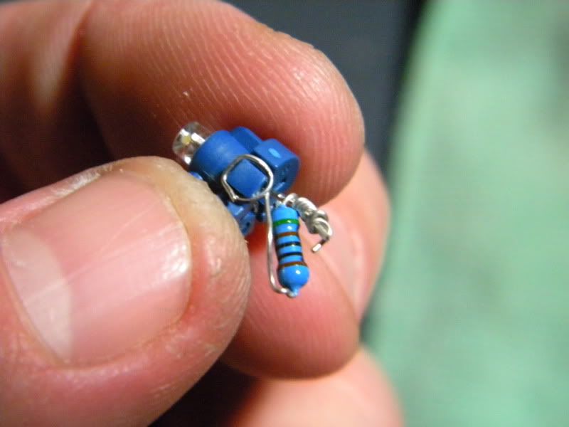
Take the legs of the LED and press them out, kinda making it look like it's a little chair. Take the anode leg and point at a 90-degree angle. Once this is done, trim both legs to ABOVE the little notched point on the LED and get ready for some fun!
STEP VIII - HAPPENS IN 3S...
Ok, here's where the fucking sucks factor reached epic heights. Take the cathode leg and place some flux on it...and dab a liiiiitle bit on the contact pad of the board. Position the LED such that is replaces the old one, DO NOT LET THE CATHODE END TOUCH THE OTHER SOLDER POINT!
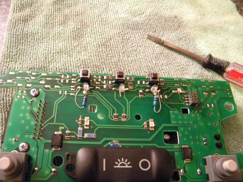
After that, flux and solder to the other leg and contact point. Place a 560-ohm resistor and solder both ends. If you take your time, or don't have shaky hands, this should be a breeze.
STEP IX - BEER O' CLOCK!
Put everything back together and crack a cold one...you're done!
I am going to try and get some more done this weekend...just do me one favor...DO NOT SEND ME ANY PMS!!! Why? You probably have questions like everyone else, and let's all learn TOGETHER, in this thread!
Take the legs of the LED and press them out, kinda making it look like it's a little chair. Take the anode leg and point at a 90-degree angle. Once this is done, trim both legs to ABOVE the little notched point on the LED and get ready for some fun!
STEP VIII - HAPPENS IN 3S...
Ok, here's where the fucking sucks factor reached epic heights. Take the cathode leg and place some flux on it...and dab a liiiiitle bit on the contact pad of the board. Position the LED such that is replaces the old one, DO NOT LET THE CATHODE END TOUCH THE OTHER SOLDER POINT!
After that, flux and solder to the other leg and contact point. Place a 560-ohm resistor and solder both ends. If you take your time, or don't have shaky hands, this should be a breeze.
STEP IX - BEER O' CLOCK!
Put everything back together and crack a cold one...you're done!
I am going to try and get some more done this weekend...just do me one favor...DO NOT SEND ME ANY PMS!!! Why? You probably have questions like everyone else, and let's all learn TOGETHER, in this thread!

Life Long Acura Fiend
Joined: May 2008
Posts: 261
Likes: 0
From: New York City
WoW nice job. Ok went thru your post twice. I know you changed the led color of the panel, My question is I want to change the Blue Map Light Bulb, what step is that at? I think i saw 2 LEDs directly on the board in step 8 is that the blue map light leds? Can that be changed?
Trending Topics
Thread Starter
Fearless DIY Guy
iTrader: (2)
Joined: Jan 2008
Posts: 3,003
Likes: 376
From: Jersey 'Burbs
Thread Starter
Fearless DIY Guy
iTrader: (2)
Joined: Jan 2008
Posts: 3,003
Likes: 376
From: Jersey 'Burbs

Thread Starter
Fearless DIY Guy
iTrader: (2)
Joined: Jan 2008
Posts: 3,003
Likes: 376
From: Jersey 'Burbs
WoW nice job. Ok went thru your post twice. I know you changed the led color of the panel, My question is I want to change the Blue Map Light Bulb, what step is that at? I think i saw 2 LEDs directly on the board in step 8 is that the blue map light leds? Can that be changed?
Gonna try and get to the rear doors and dash panel crap this weekend...I have a big party tomorrow so I hope I am not too hungover to get it done!

AZ Community Team
Joined: May 2007
Posts: 32,488
Likes: 7,771
From: N35�03'16.75", W 080�51'0.9"
WoW nice job. Ok went thru your post twice. I know you changed the led color of the panel, My question is I want to change the Blue Map Light Bulb, what step is that at? I think i saw 2 LEDs directly on the board in step 8 is that the blue map light leds? Can that be changed?
Map/Dome lights are simple. Check these two threads:
Interior LED install with pictures!!
https://acurazine.com/forums/3g-tl-2004-2008-93/interior-led-install-pictures-618468/
G-076: The definitive LED thread: all you'll ever need to know about LED's
https://acurazine.com/forums/car-parts-sale-361/sale-comptech-springs-so-cal-area-173833/
Last edited by Bearcat94; Oct 2, 2009 at 08:34 PM.
Nice write up, Six! Thanks for the kudos.
A few comments based on my project:
1) You should make sure you insulate your wires. A lot of the switches in the car are in tight places and can make contact with numerous other items. One wrong short and poof! You can use electrical tape, shrink wrap, hot glue or that fancy smancy liquid insulator to cut down on the possibility of shorts.
2) Get your self a Service Manual to assist with the disassembly of the car to get to some of these bulbs---it will help tremendously. The car itself is put together like Lego blocks---Its pretty easy to take apart if you have directions. Be careful with some of the plastic trim pieces (especially on the center console) and if you have questions, ask.
Six chose a fairly easy component for his first post---I can't wait to hear how some of his future projects go!
3) I used 470ohm resistors. All parts are from Oznium.com. The blue LEDs had a suggested resistor rating of 470ohm. Other colors require different values. Do your homework.
I have some instructions for the Steering Wheel lights--no pics. Six, you want me to post them up to this thread?
Thread Starter
Fearless DIY Guy
iTrader: (2)
Joined: Jan 2008
Posts: 3,003
Likes: 376
From: Jersey 'Burbs
1) You should make sure you insulate your wires. A lot of the switches in the car are in tight places and can make contact with numerous other items. One wrong short and poof!
You can use electrical tape, shrink wrap, hot glue or that fancy smancy liquid insulator to cut down on the possibility of shorts.
2) Six chose a fairly easy component for his first post---I can't wait to hear how some of his future projects go!
3) I used 470ohm resistors. All parts are from Oznium.com. The blue LEDs had a suggested resistor rating of 470ohm. Other colors require different values. Do your homework.

I have some instructions for the Steering Wheel lights--no pics. Six, you want me to post them up to this thread?

Thread Starter
Fearless DIY Guy
iTrader: (2)
Joined: Jan 2008
Posts: 3,003
Likes: 376
From: Jersey 'Burbs
 (not my pics)
Thread Starter
Fearless DIY Guy
iTrader: (2)
Joined: Jan 2008
Posts: 3,003
Likes: 376
From: Jersey 'Burbs

Intermediate
Joined: Sep 2007
Posts: 49
Likes: 0
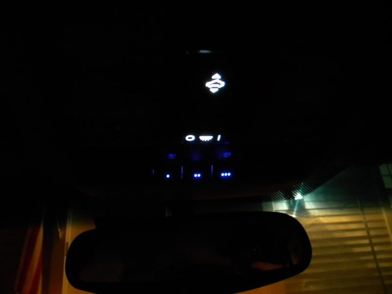
See those two little blue lights above the homelink button? Well one of them don't work in my car. I was wondering if i can get a replacement bulb to swap it from Acura or do i need to change the entire console?
Please let me know. Thanks!
Please let me know. Thanks!
I doubt that you can get a replacement from Acura for those lights. They would probably just sell you a replacement console piece.
I looked at replacing those when I was doing this part of the car, but I chose not to. For those who are unsure which lights we are talking about, scroll up to Section VIII and you will see 2 rectangular white LEDs on the circuit board below the modified LEDs near the "+" signs on the circuit board. These are the "night lights" which shine down on the cupholder area of the center console for ambient nighttime lighting. They look like SMD or SMT LEDs but the reason I did not replace them was that I was unsure of their brightness compared to the SMDs I purchased from Oznium.com. They are intended as a very low-light illumination of the driver/passenger center console area and are already blue (in base TLs). I was afraid the Ozniums would be too bright. When I replaced the drivers side window master switch LEDs with the Oznium's (all SMD LEDs), the result was very bright which I didn't want on the console at night. Seriously, you can't see it in any of the pics I have taken, but those window switch LEDs actually cast a glow on the entire drivers side door panel, they are that bright.
If you were to replace them, it would be a matter of holding the soldering tool tip to either side of the LED while pulling gently away from the circuit board. Make note of the orientation of the LED, as there is still a + and - side to SMDs. Be careful that you do not pull up the copper lead or over heat the board and burn it. Take your replacement LED, orient it correctly and solder it in. Should be pretty easy, once you get the console itself apart. I don't believe resistors are needed for this application, as they are already present on the board right next to the stock lights. You may need to research their value to make sure you don't exceed any limits. I'm no electrical engineer, so someone else may have better advice than I.
Thread Starter
Fearless DIY Guy
iTrader: (2)
Joined: Jan 2008
Posts: 3,003
Likes: 376
From: Jersey 'Burbs
UPDATE: NOTE FOR THOSE USING WHITE LEDS
I hate to bump all of the threads, but there is an important item that needs to be noted; some of the white LEDs have been burning out, which can be attributed to one thing and one thing only: thermal overload. Therefore,
IT IS HIGHLY RECOMMENDED THAT A 1K-OHM RESISTOR BE USED FOR ALL WHITE LEDS.
I have begun the process of replacing LEDs/resistors for the dearly-departed and can state that the new resistors seem to do the trick.

Oh man looks very familiar I have tackled sooo many LED projects on my Legend. If you guys want to buy SMDs I could get them from Digikey.com or Newark.com much cheaper then places like Oznium.com. Also good advice on the 1K resistors 470ohm is way to low because it doesn't account for voltage spikes up to 14.4V they will be flickering within a year for sure. Also where possible a voltage regulator is the best insurance on keeping your LEDs running for years
Thread Starter
Fearless DIY Guy
iTrader: (2)
Joined: Jan 2008
Posts: 3,003
Likes: 376
From: Jersey 'Burbs
Check out the worklog or the other DIYs, lots of good stuff!
You got it, dude. I don't recommend either of the two for sourcing LEDs, eBay offers a much wider selection at a more cost effective price point (after certain quantities)
Oh man looks very familiar I have tackled sooo many LED projects on my Legend. If you guys want to buy SMDs I could get them from Digikey.com or Newark.com much cheaper then places like Oznium.com. Also good advice on the 1K resistors 470ohm is way to low because it doesn't account for voltage spikes up to 14.4V they will be flickering within a year for sure. Also where possible a voltage regulator is the best insurance on keeping your LEDs running for years

 IDK where I got that shit from LOL
Most cheap eBay LEDs are pure Chinese junk, manufactured using low grade resins and have a very low tolerance for voltage fluctuation. That is one of the main reason you might be seeing failures and while higher resistance may prolong the life its usually just a matter of time. I learned the hard way after about 6 years working with cheap eBay leds eventually 1-2-3 years down the road they had all been replaced 2-3 times because they started to flicker. The amount of work involved in these projects is very high especially when you are taking about your dash, soldering, etc. Going cheap with your LEDs is about the worst thing you can do because once they start failing your gonna be ripping your dash apart again and kicking yourself in the meantime. Stick to brands like Cree, OSRAM, superflux and you will thank yourself down the road at a small premium you pay for quality. You do good work deathmetal and I know you have a long list of projects just like me this is one you don't want to do more then once!
Dan,
how'd you do the moonroof switch where the connector is actually on the way (on top of the bulbs)? I've tried to use SMD resistors since it's smaller, but the connection still hit the bulbs when you try to either plug it back in or remove it. it basically broke off my resistor from the bulb.
Can you show how you did it?
Also I've followed your way to do the LEDs from the circuit board and only my far left one works (same way you showed your pictures on step VIII). My middle one and right one aren't lighting up.....did I do something wrong?
update for those who will tackle this task:

The resistors and leds are soldered in reverse for the middle and right ones. Just flip them around and you're good to go!!
Also for the moon roof switch, negative is located away from the connector pins. Minimum space to work with since the connector is directly on top of the bulbs once it's plug in. Have the resistor away and as flat as possible so the connector won't jam on the resistor and break your hard work!!
That's all folks!!
Done this tonight and I can finally sleep now!

i have an 04 TL so my circuit board looked a bit different but thanks to this thread i was able to figure it out. thanks for all the info! little by little i'm making progress