When you click on links to various merchants on this site and make a purchase, this can result in this site earning a commission. Affiliate programs and affiliations include, but are not limited to, the eBay Partner Network.
Ok, after roger555 did this and changed some things I figured I would attempt it as well. It was so easy; I decided to write up a DIY for it. This will help with either replacing the Cluster itself, or doing lighting mods. I have a 2004 automatic, so depending on your vehicle this may or may not be 100%, but it should give you an idea on what to do. I or anyone supporting this will not take responsibility for you doing to do this and screwing up. It is a very easy process, but if you screw something up, I cannot and will not be held responsible. This DIY is for people who are comfortable with doing things. Please read over entire DIY before attempting to do any mod. If you have any questions, you can contact myself or anyone else that has done the steps and is willing to help you.
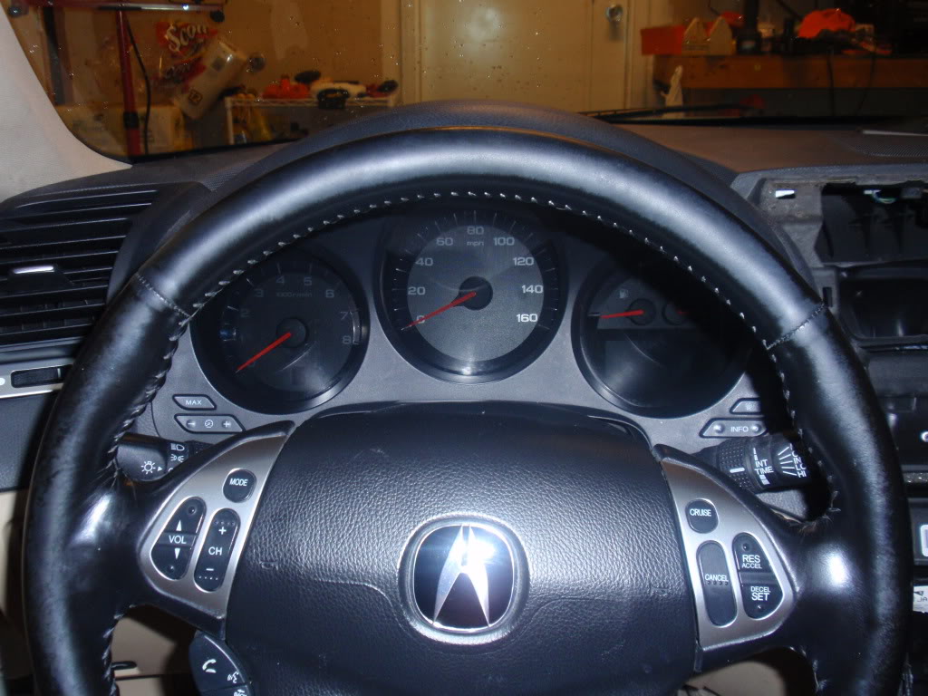
Step 1: Drop the Steering wheel all the way down. If you don't, the rest will be a PITA.
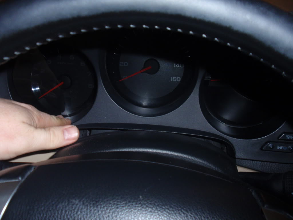
Step 2: While holding the bottom of each of the outside holes, give a good pull and the shroud should come right out.
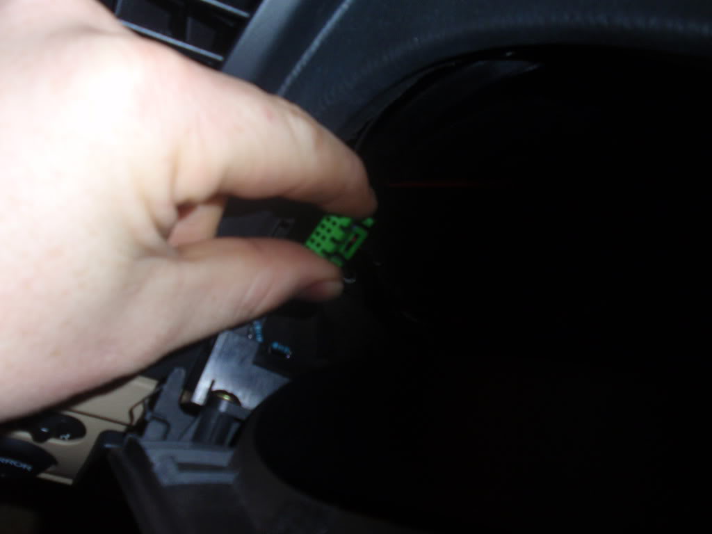
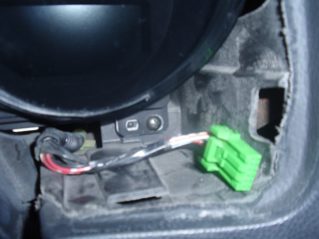
Step 3: Undo the connectors from the switches on either side of the shroud
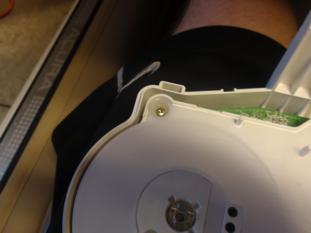
Step 4: Undo the four (4) screws holding the cluster in place. Two (2) on bottom Side corners and two (2) center top.
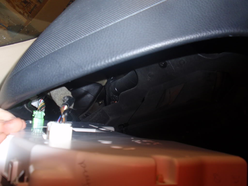
Step 5: Start wiggling out the cluster. When you get it far enough out to get your hands in. Take off the two connectors on the back of the cluster.
Step 6: Wiggle it the rest of the way out, past the steering wheel. You will need to go off to one of the sides of the steering wheel because it will not if through the wheel itself.
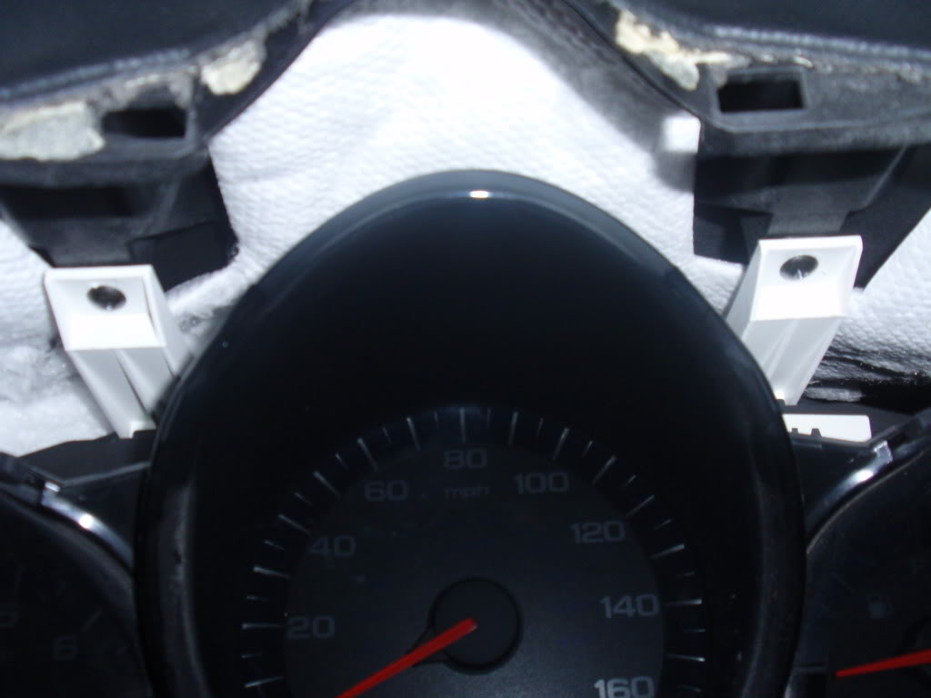
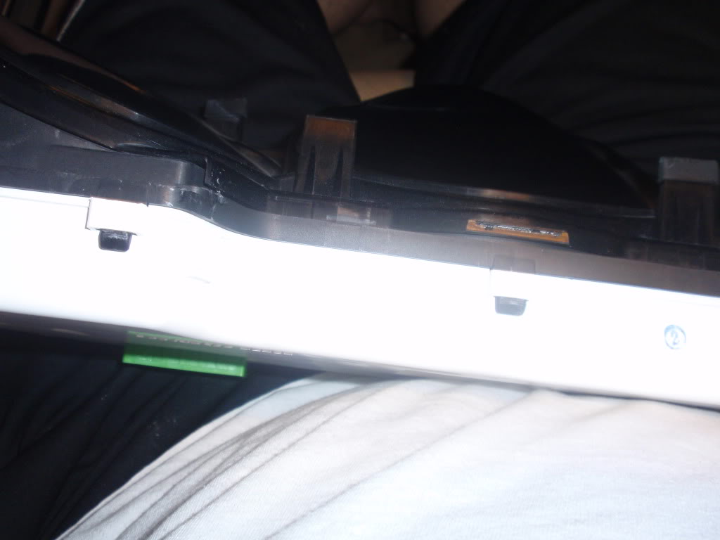
Step 7: Push out some of the clips that hold the black cover to the white. Once some of them are pushed out, usually the whole cover will come off. If not, just push out more of the clips.
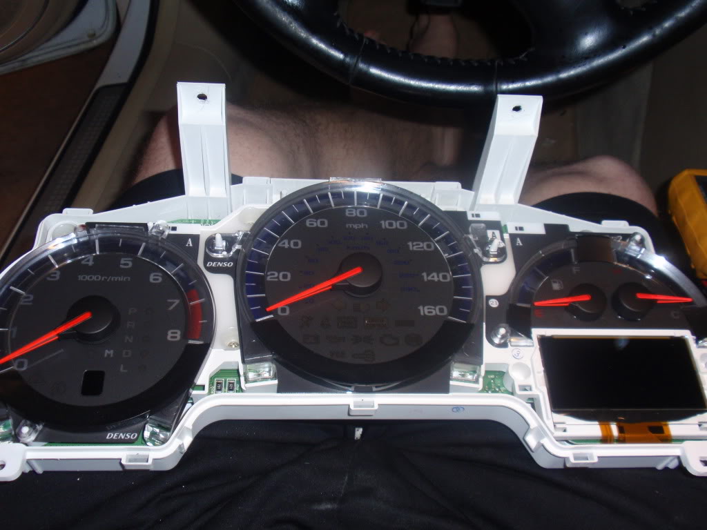
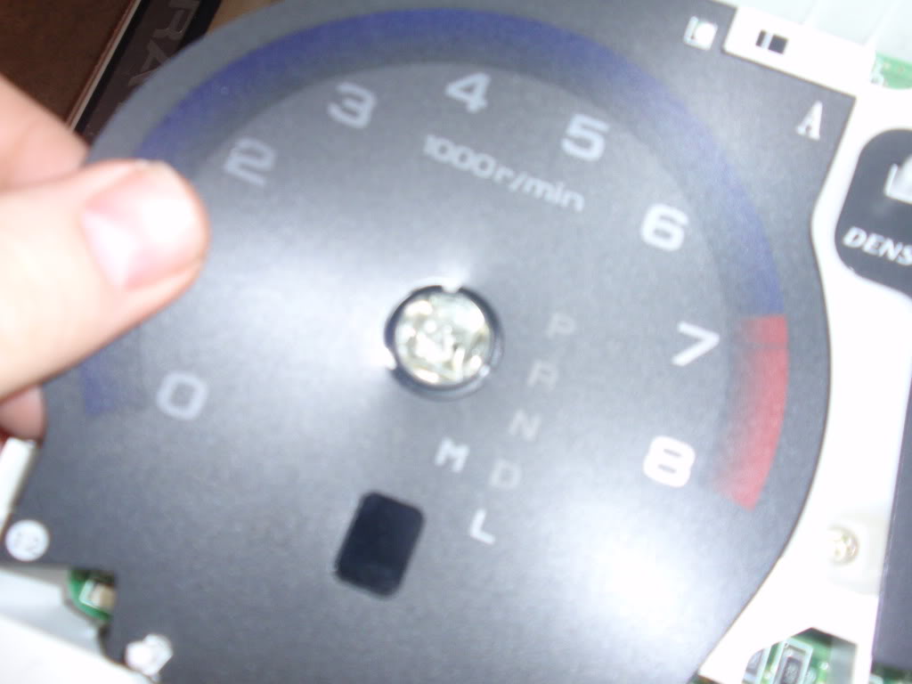
Step 8: Once you have the cover off, this is what you have in front of you.
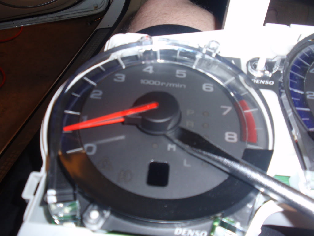
Step 9: Now let�s get those gauge needle off. Take a decent size screw driver and carefully place it under the black part of the needle. While pulling up with your fingers, gently twist the screw driver and it should pop right off without any damage.
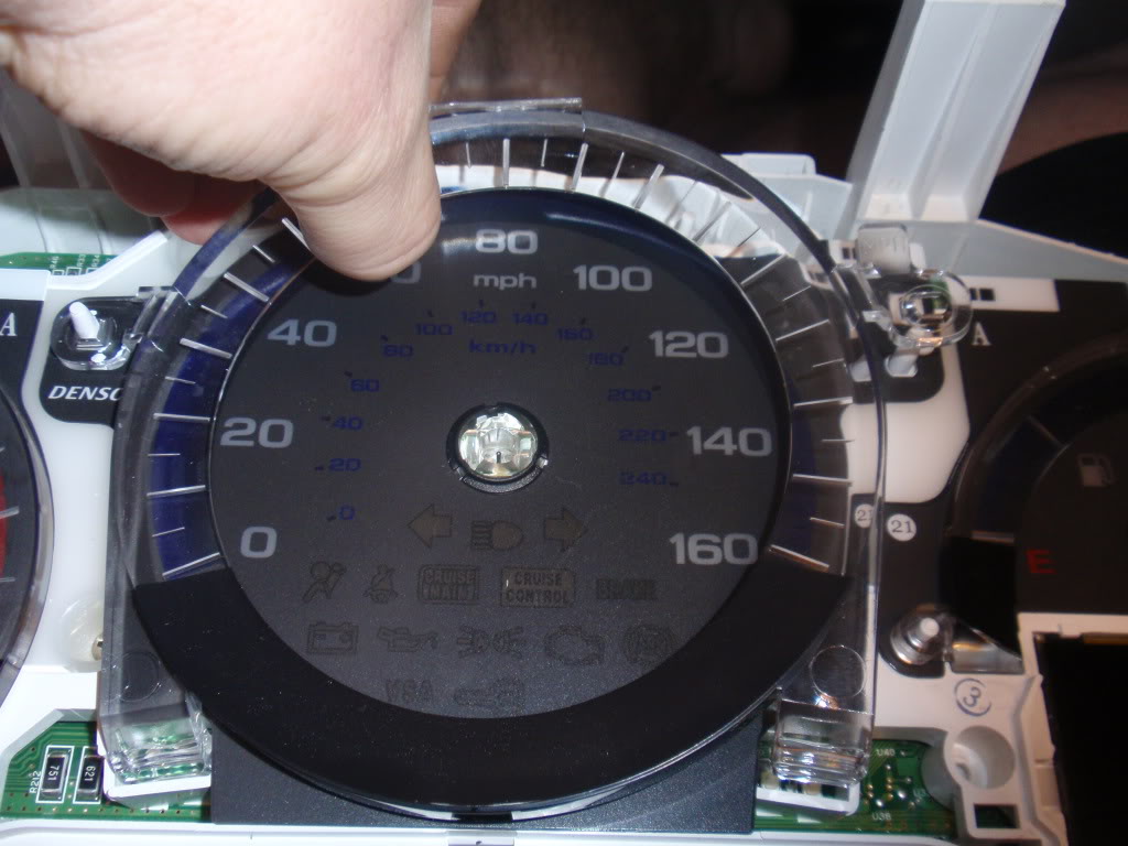
Step 10: After removing the needles, carefully remove the plastic rings around the gauges.
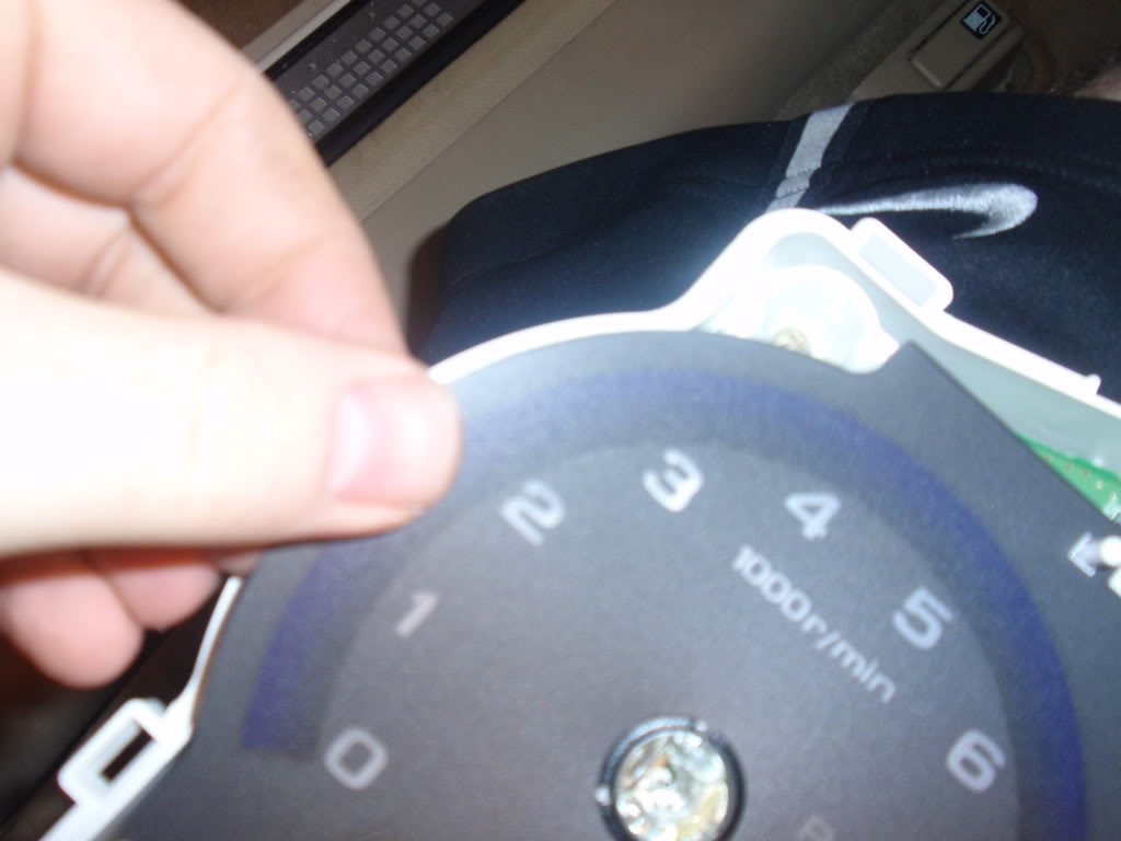
Step 11: Very Carefully pull up the gauge backing. When I did it, the center ring popped off. If yours doesn�t, take a finger nail or something very thin, then get under it and pry it up.
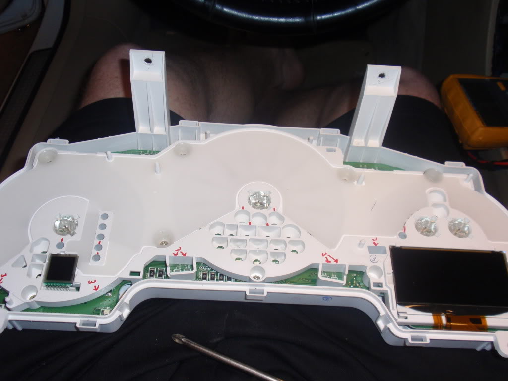
Step 12: After you remove the backing. You can have a chance to look at it through the light. At this point you can cover up the back of KM/h numbers with something. (I used electrical tape). But also at this point, if you want to go farther; Go ahead and undo all the screws that you see on the white piece with the circuit board. I recommend leaving the screws in until after the next step.
Step 13: Pull up on the opaque white piece. The screws will come up with it. Go ahead and remove all the other screws after this point.
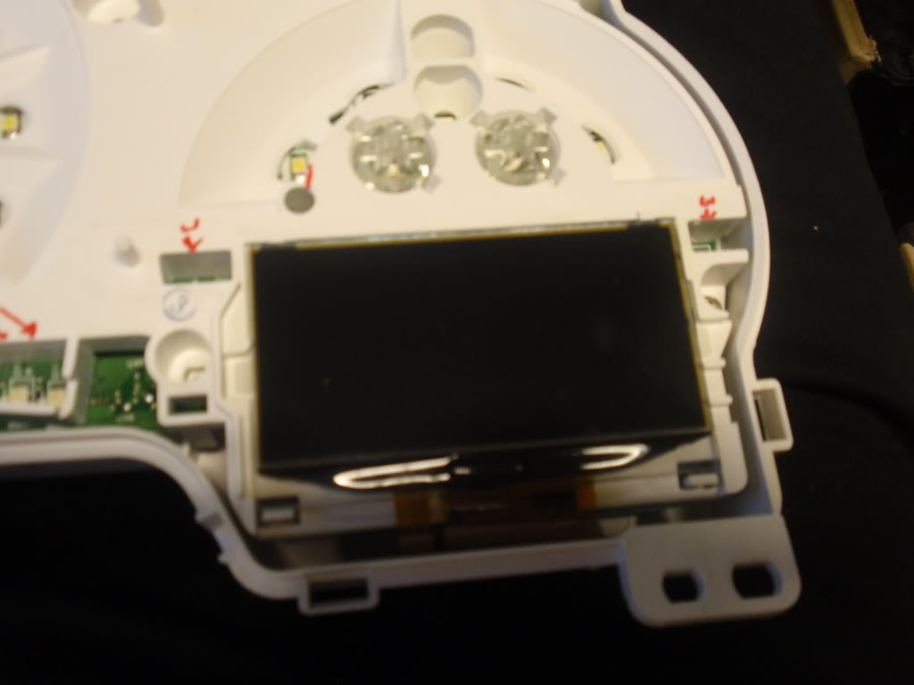
Carefully pull back on the clips that are holding the LCD screen on place and pull it out. You will not be able to remove the ribbon cable from this, so it will just have to hang. So be extremely careful after this point. We do not want to break the LCD screen. There is an opaque film behind the LCD screen. (don�t loose this.
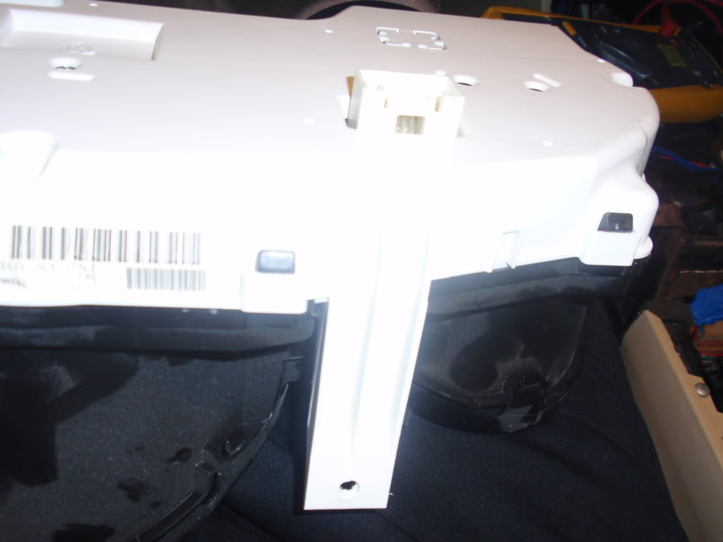
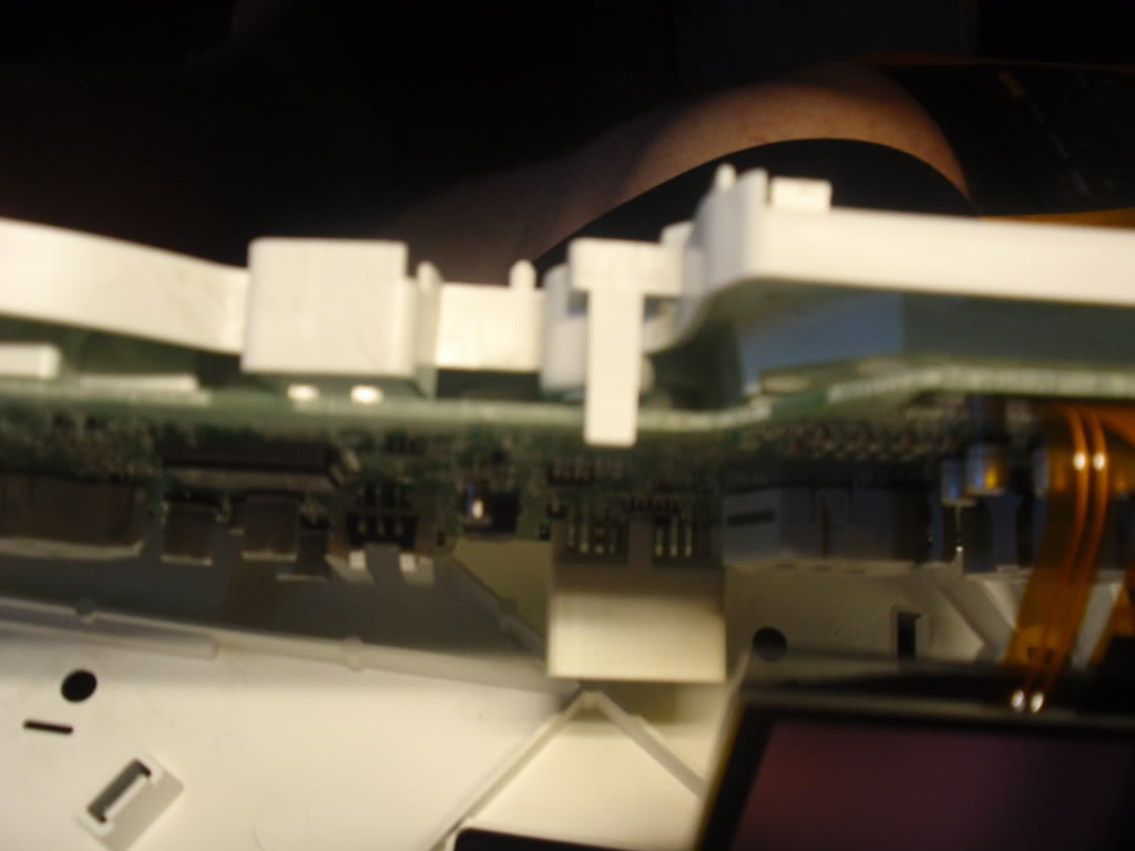
Step 14: You have two clips through holes on the back holing the white circuit board cover in place. Undo them and carefully pull off the cover, the manual gear indicator has pins going to the circuit board. You do not have to remove the small LCD screen from the circuit board cover. Just be careful when pulling it off. Sorry, forgot to take pic of this. Will get pic once I remove it again.
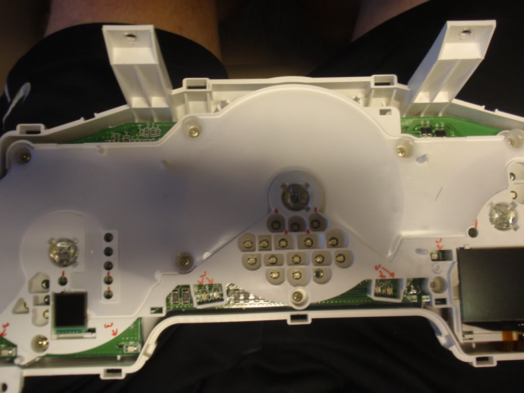
Step 15: Now you have four (4) clips holing the white backing onto the circuit board, go ahead and undo them.
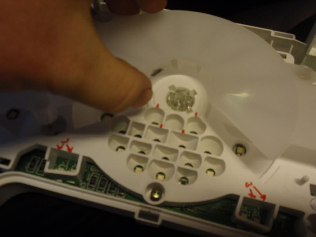
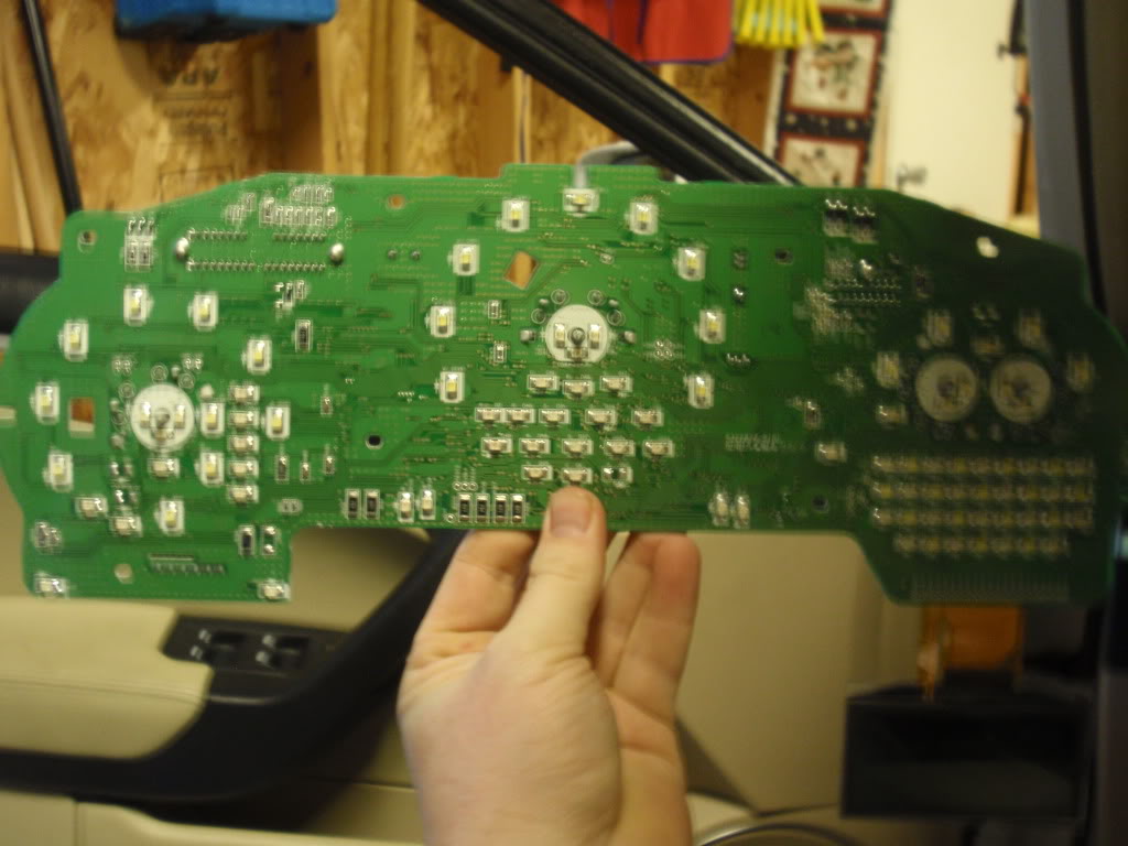
Step 15: Carefully remove the circuit board from the backing and this is what you are left with.
This is the point where you can plug it back into the car and see what LED�s are what. Behind the information LCD screen, we have a matrix of Amber and White LEDs, we can swap these out to any color and make our display very unique. I am personally doing what roger555 did and changing the tick marks to white. This takes 8 LEDs to replace the blue ones.
Personal thanks goes out to Roger555, to have pictures of it torn apart that gave me the balls to do this.
What kind of LEDS are used? Any way of getting rid of the blue completely? This would be so easy if an aftermarket company were to make the faces for the gauges, like what are available for most cars. USR was working on some but doesn't seem like that went anywhere
What kind of LEDS are used? Any way of getting rid of the blue completely? This would be so easy if an aftermarket company were to make the faces for the gauges, like what are available for most cars. USR was working on some but doesn't seem like that went anywhere
The blue comes from the gauge backing, except for the tick marks which come from some blue LEDs that feed the plastic rings from the bottom. The gauge backing is slightly transparent where the blue, red and numbers are at. The LED type would be PLCC-2 or PLCC-4. Those would be for an exact fit. The PLCC-4 would be a little brighter than the PLCC-2 but they are the same size. I use the site http://www.nixtronixonline.com. They only have white for the PLCC-4, but many different colors for the PLCC-2.
I forgot to mention in Step 9. The needle sits on a pin that bottoms out and tops out near the same point, so when you put it back together you can make sure it is back on the min points of the gauge just by twisting a little one way and if you go too far, turn the needle the other way until it stops and give it a little more twist. You can keep going back and forth until you are at the point that you want the needle to bottom ouot at.
Have you tested your car since you put everything back together? Are your tach and speedometer readings working fine after you put the needles back on?
Everything works perfectly fine, except i need to readjust my gas needle, it sits a little too high, i will be taking it apart again this weekend to replace the rest of the LEDs and adjust the gas needle, I only changed two LEDs at first to see what it looked like. Now since i like it, i got the rest of them ordered and finally got here today, I will be changing the Blue LEDs that make the Tick marks and make them white, like Roger555. I am thinking possibly at somepoint chaning the backlight on the LCD screens, just to be more unique. there are so many different colors from pink to blue, to yellow/gold.whatever you would like.
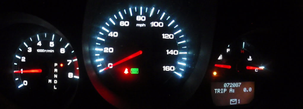
I decided to finish up to LED changeover tonight. I also got rid of the blue "back-lighting" or "ring" by covering it up from behind with electrical tape. You have to be careful and not cover up any of the numbers except the km/h (if you want to get rid of it). I cut the electrical tape so that the RPM red would still be on the gauge but the blue leading up to it would be gone. Mt next project will be to change the LCD back-lighting. Just have to figure out the color i want. Sorry, i forgot to get the pic i forgot the first time. Here is a pic of how my Cluster looks now. It looks more white in person and is still dimable. Damn panorama function on the camera messed up a little, but still the idea is right there I used the exact same LED's that are originally on the cluster board. They are PLCC-2. I used white, but you can do whatever color you would like, they even make pink if thats your thing.
Last edited by jokerman826; 01-06-2012 at 11:41 PM.
Hey man just saw this post glad you go it figured out! I'm about to attempt to put a 07 cluster in my 06. From what i've seen its plug & play except for the Airbag light due to a communication difference between the years. I'll let you know how it goes.
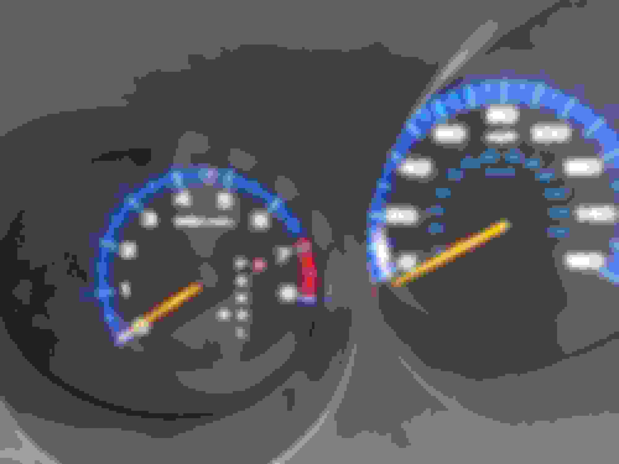
Very good write up. I had some leds (white) from the radio led mod so i attempted this since everything else in the cabin was brighter. Fairly easy. Using PLCC-2 bright white I just did the middle ring portion of the speedometer first. Like I said I had some extra leds so I did the 3 needle leds too but since I only had white ones they turned out to be more of an orange color. I'm gonna switch to red on the next soldering mission.
The right is the newly soldered leds. Note that I replaced the needle LED (they were originally red) to white so now it is an orange color.
NP, i have been MIA for a few years. I am surprised this never made it into the Garage, Oh well. Thread revived for a new generation.

 12-31-2011, 12:25 PM