
Attn all who want LED turn signals and normal flash rate
 02-03-2006, 05:54 PM
#1
Advanced
Thread Starter

Join Date: Feb 2003
Location: Austin, TX
Posts: 57
Likes: 0
Received 0 Likes
on
0 Posts
Ok, I've got to make this short and as such minus much of the details you might want right now, but this is mostly for you guys as I am going to keep bulbs in mine. this past week I removed, baked, opened, and blacked out my headlights roughly following some of the well documented instructions in the TL Garage so I thought I'd give something back. the only major differences I did with mine were protecting the reflective area directly behind the turn lamp with electrical tape during painting to preserve it's function, baking the silica pack and adding my own, using E6000 to reseal instead of black silicon, and airbrushing the peices with man, many freakin coats. I don't have pictures on this comp, but I willl soon. NBP btw, and the process wasn't nearly as bad as I was expecting.
NOTE: I have not done this! I only have begun the groundwork for whichever pioneering soul on this board wants to take the next leap! (Requires small tools, and soldering surface mount components.) I am however 100% certain of the feasibility and correctness of the approach, someone just needs to be first.
So, to the point. We know why the blinker changes rate (2.2 times faster to be exact) when the bulbs are replaced with LED's, this is a feature that when we aren't butting our heads against it is nice to have, even though LED's will likely not need to be replaced through the duration of the vehicles life, the rear turn signals might be. The low current flashers available do not seem to fit our cars, so where does this leave us? With modifying the original equipment of course! Something this board seems to <i>love</i>. I crawled under the dash and turned on the blinker to find the flashing module, pictures would be nice here but again---I'm in an airport at the moment, so do what I did! It's gray, and located above the fuse panel in the drivers side kick panel. It's loud and you can feel it function as the mechanics of the relay cycle, you can't miss it. So, carefully, and this parts a bitch---pry it out by holding back the two restraining clips on either side and pulling. The plastic is a bit fragile, so be careful. Then open it, using a small precision flat blade, or an axe. you are now looking at the resin board with all the silicon parts and passive components----the one of most importance here is a Motorola chip with "33193" printed on it, this is the "brains" of the operation. Go here----><url>http://www.freescale.com/files/analog/doc/data_sheet/MC33193.pdf</url> to get a copy of the data sheet for this part. If you know your way around a schematic, check out the second app. note. This is roughly how Honda deployed this peice, read the descriptions for the functions of the chip and pay close attention to pin 7 and the "Fault Detection" pin and related components. the fault detection---as described in the datasheet---of this unit works by comparing an internal voltage source, with the voltage drop across the parallel lamp circuits (front and back flash simultaneously). Pin 7 in connectred to the middle of what is sometimes called a voltage ladder, with Rs being the "upper" portion and the equivelent resistance of the lamps being the "lower" portion. This ratio determines the voltage "seen" by pin 7, -when a bulb goes out, the resistance of the "lower" portion of the ladder is subsequently increased, actually doubled for either side. In our case, the LED simulates a failed bulb because of the characteristics of low power Si junctions, much higher impedence. What we want to do here, is remove Rs and replace it with another resistor of different value to maintain this ratio, "recalibrating" the device into functioning normally. At first I thought about altering the oscillating frequency by changing R1/C1 and leaving the device in this fault condition, but this would defeat this handy little feature. I took some high res pics of the board, which--of course---are at home, and I located Rs by following the short traces on the PCB. You can do this to, or wait until I can get you guys some better pics if you're nervous but I am confident there are a number of persons here who can do this. Determine the current drain of the LED lights you plan on using, this will likely be diff. for each type of LED bulb. Using our friend Ohm's and his law, reconstruct your new virtual voltage ladder and note the required value of Rs. (The V-range that pin 7 looks for is listed in the datasheet, if you're not familiar with voltage ladders Google it and learn yourself something real quick, you might surprise yourself!) Now go to Mouser, Digikey, or whichever SMT part ditributor you prefer and order a couple of surface mount resistors, --get a couple because they are cheap and if you drop one in the carpet, you're SOL. Whip out your soldering iron with SMT tip and remove Rs, replacing it with your new resistor. Reassemble, drink a beer, and test that sucker out. There might also be a way to bypass the feature by shunting pin 7 low, but I doubt this would work as the range is rather specific.) Anyone out there who actually has an EE degree please look over it for these guys, maybe you can find a better way. I'm a Physics guy, the force is not with me on this.
Why this way over the load resistor? Because no self respecting, technical minded person would include such a troglodite setup in their Acura. The loading res. get VERY hot because they are wasting a good amount of energy, loading your electrical system and risking fire, premature failure, and embarrasment if anyone else sees the damned thing. If you were my neighbor, I would make fun of you. This method retains the digital control and "sexiness" of the oem setup with the addition of "better" lights.
I'm keeping bulbs in mine for brightness, I have yet to be convinced that even with my retained reflective areas that LEDs would provide enough visibility for other drivers. But, I'm hoping some of you guys get on this, and show us how bright they are. I've seen some pics, but I'm going to wait a bit.
BTW: If you want to be extra safe, get a spare flasher from Acura in case you screw up the test mule, this way you won't have to drive to the dealer without turn signals. Return it later if you don't need it.
 02-03-2006, 06:15 PM
#2
Holdin it down for MS
Join Date: Oct 2005
Location: Mississippi
Age: 37
Posts: 328
Likes: 0
Received 0 Likes
on
0 Posts
Oh my god. 
1. Bro, they are called paragraphs. They make things MUCH easier to read! I know you are literate because I scanned your clump of words and picked out some commas and periods and hyphens, so we are ok there, but DAYUM!
2. Cliff Notes. Post haste.
1. Bro, they are called paragraphs. They make things MUCH easier to read! I know you are literate because I scanned your clump of words and picked out some commas and periods and hyphens, so we are ok there, but DAYUM!
2. Cliff Notes. Post haste.
02-03-2006, 06:24 PM
#3
Safety Car
Oye! I was trying to read your post.. but then my eyes blurred.. I lost my place and your post turned into one of those "Magic Eye" pictures.. I can't make out what the hidden picture is 
02-03-2006, 08:40 PM
#4
Drifting
So the TL actually has a flasher? Did you actually do this, or are you just thinking outloud? Because I know on my G35, there is no flasher. And that clicking sound you hear, is fake, and is actually made by the same mechanism that chimes when you open the door with the keys in the ignition.
Your directions seem so complicated. Seems easier to just wire in some resistors with the LEDs.
Your directions seem so complicated. Seems easier to just wire in some resistors with the LEDs.
02-03-2006, 11:25 PM
#5
Racer
Join Date: Dec 2005
Location: Irvine
Age: 53
Posts: 401
Likes: 0
Received 0 Likes
on
0 Posts
Actually, his statement makes sense and is better for a long term solution. Instead of 'tricking' the system with a resistor to load the circuit, you are basically 're-calibrating' the flasher to work with the new lighting setup. If I was going to do the LED mod, I would much rather go this route than the resistor.
I have done a resistor mod in my old 83 RX-7 when 'ambers' were in and I made them dim with resistors which made everyone 'oohhh' at them. But that resistor got REALLY HOT to the point I put heat sinks on it.
I may have to try this if I ever decide to LED my turn signals. Please post pics when you get a chance.
02-04-2006, 12:02 AM
#6
Three Wheelin'
Fuck im editing this so i can read it !
Originally Posted by Manic
Ok, I've got to make this short and as such minus much of the details you might want right now, but this is mostly for you guys as I am going to keep bulbs in mine. this past week I removed, baked, opened, and blacked out my headlights roughly following some of the well documented instructions in the TL Garage so I thought I'd give something back.
the only major differences I did with mine were protecting the reflective area directly behind the turn lamp with electrical tape during painting to preserve it's function, baking the silica pack and adding my own, using E6000 to reseal instead of black silicon, and airbrushing the peices with man, many freakin coats. I don't have pictures on this comp, but I willl soon. NBP btw, and the process wasn't nearly as bad as I was expecting.
NOTE: I have not done this! I only have begun the groundwork for whichever pioneering soul on this board wants to take the next leap! (Requires small tools, and soldering surface mount components.) I am however 100% certain of the feasibility and correctness of the approach, someone just needs to be first.
So, to the point. We know why the blinker changes rate (2.2 times faster to be exact) when the bulbs are replaced with LED's, this is a feature that when we aren't butting our heads against it is nice to have, even though LED's will likely not need to be replaced through the duration of the vehicles life, the rear turn signals might be.
The low current flashers available do not seem to fit our cars, so where does this leave us? With modifying the original equipment of course! Something this board seems to <i>love</i>. I crawled under the dash and turned on the blinker to find the flashing module, pictures would be nice here but again---I'm in an airport at the moment, so do what I did!
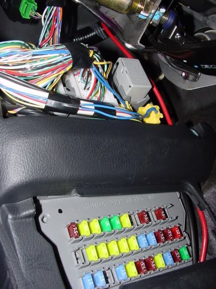
It's gray, and located above the fuse panel in the drivers side kick panel. It's loud and you can feel it function as the mechanics of the relay cycle, you can't miss it. So, carefully, and this parts a bitch---pry it out by holding back the two restraining clips on either side and pulling.
The plastic is a bit fragile, so be careful. Then open it, using a small precision flat blade, or an axe. you are now looking at the resin board with all the silicon parts and passive components----the one of most importance here is a Motorola chip with "33193" printed on it, this is the "brains" of the operation. Go here http://www.freescale.com/files/analo...et/MC33193.pdf to get a copy of the data sheet for this part.
If you know your way around a schematic, check out the second app. note. This is roughly how Honda deployed this peice, read the descriptions for the functions of the chip and pay close attention to pin 7 and the "Fault Detection" pin and related components.
the fault detection---as described in the datasheet---of this unit works by comparing an internal voltage source, with the voltage drop across the parallel lamp circuits (front and back flash simultaneously). Pin 7 in connectred to the middle of what is sometimes called a voltage ladder, with Rs being the "upper" portion and the equivelent resistance of the lamps being the "lower" portion.
This ratio determines the voltage "seen" by pin 7, -when a bulb goes out, the resistance of the "lower" portion of the ladder is subsequently increased, actually doubled for either side. In our case, the LED simulates a failed bulb because of the characteristics of low power Si junctions, much higher impedence.
What we want to do here, is remove Rs and replace it with another resistor of different value to maintain this ratio, "recalibrating" the device into functioning normally. At first I thought about altering the oscillating frequency by changing R1/C1 and leaving the device in this fault condition, but this would defeat this handy little feature.
I took some high res pics of the board, which--of course---are at home, and I located Rs by following the short traces on the PCB. You can do this to, or wait until I can get you guys some better pics if you're nervous but I am confident there are a number of persons here who can do this. Determine the current drain of the LED lights you plan on using, this will likely be diff. for each type of LED bulb.
Using our friend Ohm's and his law, reconstruct your new virtual voltage ladder and note the required value of Rs. (The V-range that pin 7 looks for is listed in the datasheet, if you're not familiar with voltage ladders Google it and learn yourself something real quick, you might surprise yourself!) Now go to Mouser, Digikey, or whichever SMT part ditributor you prefer and order a couple of surface mount resistors, --get a couple because they are cheap and if you drop one in the carpet, you're SOL.
Whip out your soldering iron with SMT tip and remove Rs, replacing it with your new resistor. Reassemble, drink a beer, and test that sucker out. There might also be a way to bypass the feature by shunting pin 7 low, but I doubt this would work as the range is rather specific.)
Anyone out there who actually has an EE degree please look over it for these guys, maybe you can find a better way. I'm a Physics guy, the force is not with me on this.
Why this way over the load resistor? Because no self respecting, technical minded person would include such a troglodite setup in their Acura. The loading res. get VERY hot because they are wasting a good amount of energy, loading your electrical system and risking fire, premature failure, and embarrasment if anyone else sees the damned thing. If you were my neighbor, I would make fun of you. This method retains the digital control and "sexiness" of the oem setup with the addition of "better" lights.
I'm keeping bulbs in mine for brightness, I have yet to be convinced that even with my retained reflective areas that LEDs would provide enough visibility for other drivers. But, I'm hoping some of you guys get on this, and show us how bright they are. I've seen some pics, but I'm going to wait a bit.
BTW: If you want to be extra safe, get a spare flasher from Acura in case you screw up the test mule, this way you won't have to drive to the dealer without turn signals. Return it later if you don't need it.
the only major differences I did with mine were protecting the reflective area directly behind the turn lamp with electrical tape during painting to preserve it's function, baking the silica pack and adding my own, using E6000 to reseal instead of black silicon, and airbrushing the peices with man, many freakin coats. I don't have pictures on this comp, but I willl soon. NBP btw, and the process wasn't nearly as bad as I was expecting.
NOTE: I have not done this! I only have begun the groundwork for whichever pioneering soul on this board wants to take the next leap! (Requires small tools, and soldering surface mount components.) I am however 100% certain of the feasibility and correctness of the approach, someone just needs to be first.
So, to the point. We know why the blinker changes rate (2.2 times faster to be exact) when the bulbs are replaced with LED's, this is a feature that when we aren't butting our heads against it is nice to have, even though LED's will likely not need to be replaced through the duration of the vehicles life, the rear turn signals might be.
The low current flashers available do not seem to fit our cars, so where does this leave us? With modifying the original equipment of course! Something this board seems to <i>love</i>. I crawled under the dash and turned on the blinker to find the flashing module, pictures would be nice here but again---I'm in an airport at the moment, so do what I did!
It's gray, and located above the fuse panel in the drivers side kick panel. It's loud and you can feel it function as the mechanics of the relay cycle, you can't miss it. So, carefully, and this parts a bitch---pry it out by holding back the two restraining clips on either side and pulling.
The plastic is a bit fragile, so be careful. Then open it, using a small precision flat blade, or an axe. you are now looking at the resin board with all the silicon parts and passive components----the one of most importance here is a Motorola chip with "33193" printed on it, this is the "brains" of the operation. Go here http://www.freescale.com/files/analo...et/MC33193.pdf to get a copy of the data sheet for this part.
If you know your way around a schematic, check out the second app. note. This is roughly how Honda deployed this peice, read the descriptions for the functions of the chip and pay close attention to pin 7 and the "Fault Detection" pin and related components.
the fault detection---as described in the datasheet---of this unit works by comparing an internal voltage source, with the voltage drop across the parallel lamp circuits (front and back flash simultaneously). Pin 7 in connectred to the middle of what is sometimes called a voltage ladder, with Rs being the "upper" portion and the equivelent resistance of the lamps being the "lower" portion.
This ratio determines the voltage "seen" by pin 7, -when a bulb goes out, the resistance of the "lower" portion of the ladder is subsequently increased, actually doubled for either side. In our case, the LED simulates a failed bulb because of the characteristics of low power Si junctions, much higher impedence.
What we want to do here, is remove Rs and replace it with another resistor of different value to maintain this ratio, "recalibrating" the device into functioning normally. At first I thought about altering the oscillating frequency by changing R1/C1 and leaving the device in this fault condition, but this would defeat this handy little feature.
I took some high res pics of the board, which--of course---are at home, and I located Rs by following the short traces on the PCB. You can do this to, or wait until I can get you guys some better pics if you're nervous but I am confident there are a number of persons here who can do this. Determine the current drain of the LED lights you plan on using, this will likely be diff. for each type of LED bulb.
Using our friend Ohm's and his law, reconstruct your new virtual voltage ladder and note the required value of Rs. (The V-range that pin 7 looks for is listed in the datasheet, if you're not familiar with voltage ladders Google it and learn yourself something real quick, you might surprise yourself!) Now go to Mouser, Digikey, or whichever SMT part ditributor you prefer and order a couple of surface mount resistors, --get a couple because they are cheap and if you drop one in the carpet, you're SOL.
Whip out your soldering iron with SMT tip and remove Rs, replacing it with your new resistor. Reassemble, drink a beer, and test that sucker out. There might also be a way to bypass the feature by shunting pin 7 low, but I doubt this would work as the range is rather specific.)
Anyone out there who actually has an EE degree please look over it for these guys, maybe you can find a better way. I'm a Physics guy, the force is not with me on this.
Why this way over the load resistor? Because no self respecting, technical minded person would include such a troglodite setup in their Acura. The loading res. get VERY hot because they are wasting a good amount of energy, loading your electrical system and risking fire, premature failure, and embarrasment if anyone else sees the damned thing. If you were my neighbor, I would make fun of you. This method retains the digital control and "sexiness" of the oem setup with the addition of "better" lights.
I'm keeping bulbs in mine for brightness, I have yet to be convinced that even with my retained reflective areas that LEDs would provide enough visibility for other drivers. But, I'm hoping some of you guys get on this, and show us how bright they are. I've seen some pics, but I'm going to wait a bit.
BTW: If you want to be extra safe, get a spare flasher from Acura in case you screw up the test mule, this way you won't have to drive to the dealer without turn signals. Return it later if you don't need it.
02-04-2006, 09:26 AM
#7
Drifting
Originally Posted by davenlei
But that resistor got REALLY HOT to the point I put heat sinks on it.
Trending Topics
02-04-2006, 12:37 PM
#9
Advanced
Thread Starter
Join Date: Feb 2003
Location: Austin, TX
Posts: 57
Likes: 0
Received 0 Likes
on
0 Posts
Originally Posted by avs007
So the TL actually has a flasher? Did you actually do this, or are you just thinking outloud? Because I know on my G35, there is no flasher. And that clicking sound you hear, is fake, and is actually made by the same mechanism that chimes when you open the door with the keys in the ignition.
Your directions seem so complicated. Seems easier to just wire in some resistors with the LEDs.
Your directions seem so complicated. Seems easier to just wire in some resistors with the LEDs.
Yes, I'm sure it has one and it looks exactly like this:

Sorry about the length, I was just trying to get some of the stuff I had been thinking about on the flight up. It wasn't suppposed to be directions so much as just a brainstorm, just to get the wheels for some of these guys who want this rolling.
I'll have to pulll the thingy back out when I get some free time and do a better job of following those traces, from the pic it is hard to tell as some of them follow under certain components. I plan onn doing this for sure at some point, but for now I like the amber bulbs.
About the bulbs: Amber bulbs of the right size for our parking/turn indicators are quite hard to find. I ended up using the same bulbs used in the '04 MDX with clear corners. (Honda PN# 33303-S2R-003) Size 7440, so I am missing the parking lights when they are on, but the blinkers work and are quite bright. The bulbs I really want are 7443NA, and they are only sold by a couple places I could find online, and some of those places only sell them in quantities of ten or more.
02-04-2006, 12:50 PM
#10
Advanced
Thread Starter
Join Date: Feb 2003
Location: Austin, TX
Posts: 57
Likes: 0
Received 0 Likes
on
0 Posts
I wanted to put this in the above post, but I got clipped by the five minute rule.
The guy in the lower right corner is the Motorola chip, the small black ones are the SMD resistors, and the tan ones are the capacitors. There is also a large(r) capacitor on the back side (C1) along with the two relays. The smaller black silicon devices are for feedback/short protection, driving the relays, etc. Ask Google for identifying SMD components if you're not familiar with the markings.
I would have just gone ahead and done this, then relayed the exact procedure, but I thought some of you might want to get a head start.
02-04-2006, 12:58 PM
#11
I don't really understand all of this electrical stuff, so I am just reporting what I am reading in the Service Manual.
The turn-signals are integrated into the Multiplex Integrated Control System (MICS), and the troubleshooting is done by a B-CAN System Diagnosis Test Mode A operation.
It looks like it says that if any one of the many functions controlled by the MICU are not working due to the MICU, and not some other component such as a relay or fuse, etc. being bad, the entire MICU must be replaced (page 22-109).
We have a couple of service manager/mechanic type members here who probably know how to explain this better so I hope they can reply here.
Does that black box with the circuit board in post #9 have a part number anywhere on it? That might help identify it further.
02-04-2006, 01:25 PM
#12
Advanced
Thread Starter
Join Date: Feb 2003
Location: Austin, TX
Posts: 57
Likes: 0
Received 0 Likes
on
0 Posts
Originally Posted by avs007
Which is why I put in PIAA Mirror Orange bulbs, so I didn't have to deal with it.
This method is not for everyone, it requires some degree of technical competence and appreciation. This method is better in that if acura were to include LED indicators, this is how their engineers would change the system. It releives your electrical system of over 38 watts of power while on, does not cause excess heat, and does not require modification/cutting of any of the wiring harnesses/plugs, or dismantling of the front of the car to drill holes into the frame to mount a resistor. If you want to remove it, pop it back out and stick in a new one, I think they cost right around $18 at the Honda dealership, the part number is listed on top of the gray plastic shell.
BTW: Here is a shot of one of the lights. Much better I think, I can't stand chrome!
 02-04-2006, 01:43 PM
#13
Advanced
Thread Starter
Join Date: Feb 2003
Location: Austin, TX
Posts: 57
Likes: 0
Received 0 Likes
on
0 Posts
Originally Posted by Ron A
I don't really understand all of this electrical stuff, so I am just reporting what I am reading in the Service Manual.
The turn-signals are integrated into the Multiplex Integrated Control System (MICS), and the troubleshooting is done by a B-CAN System Diagnosis Test Mode A operation.
It looks like it says that if any one of the many functions controlled by the MICU are not working due to the MICU, and not some other component such as a relay or fuse, etc. being bad, the entire MICU must be replaced (page 22-109).
We have a couple of service manager/mechanic type members here who probably know how to explain this better so I hope they can reply here.
Does that black box with the circuit board in post #9 have a part number anywhere on it? That might help identify it further.
The turn-signals are integrated into the Multiplex Integrated Control System (MICS), and the troubleshooting is done by a B-CAN System Diagnosis Test Mode A operation.
It looks like it says that if any one of the many functions controlled by the MICU are not working due to the MICU, and not some other component such as a relay or fuse, etc. being bad, the entire MICU must be replaced (page 22-109).
We have a couple of service manager/mechanic type members here who probably know how to explain this better so I hope they can reply here.
Does that black box with the circuit board in post #9 have a part number anywhere on it? That might help identify it further.
This module functions indepedently of the MICU, there is no mechanism by which it would communicate or rely on outside circuitry. I breifly powered it up on my workbench and got it to flash (in fault mode) as expected for a number of minutes. The relays are quite loud when they operate, and probing a couple points on the board with a DMM produced the expected results. There are six pins connected externally to the cars electrical system, these pins are divided up into the 12V supply rails, both sets of lamps&/dashboard indicators, turn signal switch, and ignition/hazard. Which ones are which can be determined by following the traces, and using a continuity test for each traces that disappears under or behind something. Again, this all seems a little premature because I'm having to be so vague on some things, but this is for the guys who are dying to get started on this. I guess I'm passing the torch for the moment, eventually I will do this myself though, right now I'm just swamped with work and having to be out of town next week. Cheers!
02-04-2006, 02:20 PM
#14
Advanced
Thread Starter
Join Date: Feb 2003
Location: Austin, TX
Posts: 57
Likes: 0
Received 0 Likes
on
0 Posts
Ok, here is a pic of the blinker module as it sits in the car. It is the light gray box, I chipped the plastic casing while taking it apart, before I figured out how to do it properly.
Here is a shot of it out of the car, with the numbers visible.

This is an angled shot, showing the six i/o, and another stamped number.
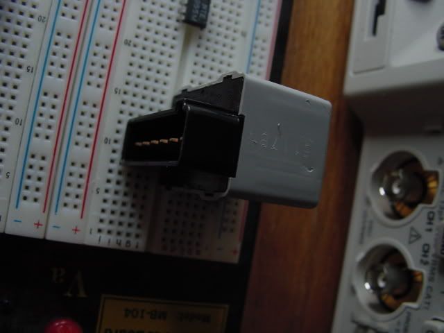
Photobucket resizes these pics so it might be harder to read the numbers, I can send you the originals if you want.
Oh, and Ron----I think I mistook your question about the numbers earlier, I think you were talking about the numbers on the module itself, and not the chip. I get it now, see pics.
Here is a shot of it out of the car, with the numbers visible.
This is an angled shot, showing the six i/o, and another stamped number.
Photobucket resizes these pics so it might be harder to read the numbers, I can send you the originals if you want.
Oh, and Ron----I think I mistook your question about the numbers earlier, I think you were talking about the numbers on the module itself, and not the chip. I get it now, see pics.
02-04-2006, 03:18 PM
#16
That is actually the turn signal/hazard relay from the under dash fuse/relay box. I am sure you checked for turn signal operation after removing this relay, and when it didn't operate you might have assumed it was the flasher.
The part number is 38300-SHJ-A04, so it could be the flasher. Is this the part that makes the noise when the turn signal is on?
And I fixed the pics in your previous post.
The part number is 38300-SHJ-A04, so it could be the flasher. Is this the part that makes the noise when the turn signal is on?
And I fixed the pics in your previous post.
12-13-2007, 08:45 AM
#18
 02-03-2008, 06:13 PM
#20
He realized that the flasher cannot be modified.
What he probably did was copy and paste all that from some other site. Its not pisslbe to "reteach" a flasher module. At least not on the TL. Only option we have is installing the load balancers.
What he probably did was copy and paste all that from some other site. Its not pisslbe to "reteach" a flasher module. At least not on the TL. Only option we have is installing the load balancers.
04-10-2008, 11:28 AM
#22
Senior Moderator
Regions Leader
Regions Leader
Originally Posted by rockyfeller
I disagree I think it can definitely be done with some modifications.
Thing is, who has the know how and wants to expend time an energy on this?
Thing is, who has the know how and wants to expend time an energy on this?
Im going to figure this out....Im not putting load resistors in this car.
If its going to be a pain in the ass I will have some LED blinkers for sale....
Ill update you shortly after my electrical guru and I go over all this....
 04-10-2008, 12:29 PM
#24
Senior Moderator
Regions Leader
Regions Leader
Originally Posted by jcondon
+1
Warning: Do not post if you have nothing more then +1 to add.
who gives a shit that he wrote a damn paragraph. dont fuckin read it if its too long
04-10-2008, 05:28 PM
#25
Instructor

Originally Posted by trancemission
Im going to figure this out....Im not putting load resistors in this car.
If its going to be a pain in the ass I will have some LED blinkers for sale....
Ill update you shortly after my electrical guru and I go over all this....
If its going to be a pain in the ass I will have some LED blinkers for sale....
Ill update you shortly after my electrical guru and I go over all this....
I'm an Electrical Engineer. I repaired the relay in my 85 honda accord once. I replaced the current sense resistor. I may be able to help you get this sorted out.
The way the turn signals work in most cars is that there is a current sense resistor in the relay box that detects how much load the flashers are drawing. It times the on time based on how much load they draw. If one goes out, it draws half the current so it's on for half the time. That is why they did it that way, so you would know that a bulb is out.
When you install LEDs, they use less power for the same light so the current sense circuit thinks that a bulb is out when really your LEDs are just more efficient. The Load resistors are then added to burn enough power to make the LEDs use as much current as the bulbs did. You are not any worse off when you had bulbs, you are just using the same amount of power to get the same flash rate. If you did add the resistors and burned more power then when you started, the flash rate would be even slower.
Here is the Quest:
Find the current sense resistor and make it larger by the factor you're off on the flashing. Even if this is controlled by the ECU, there has to be a current sense resistor and you can make it work.
A different option would be to double up on LEDs until they match the amount of power the incandescent was drawing. This would make the guy complaining about the brightness happier as well as solve the flashing rate, but then you have to figure out how to mount it.
Let me know if you find the current sense resistor. I'm not at work so I can't look at the wiring diagram to see the current path, but I may find it when I get home and look at the factory service manual for my 04 TL..
-Jeff
04-10-2008, 05:49 PM
#27
Instructor
Originally Posted by rockyfeller
I disagree I think it can definitely be done with some modifications.
Thing is, who has the know how and wants to expend time an energy on this?
Thing is, who has the know how and wants to expend time an energy on this?
Can anyone verify and take pictures of the relay flasher module on the TL?
-Jeff
04-13-2008, 04:41 AM
#28
Instructor
No Load resistors, No Problem
I pulled my relay, I can totally mod the relay to get it to flash normally without load resistors when using LEDs!
Since All LEDs are different, if you still want it to flash fast when one goes out, I have to verify the mod with the specific LED. (Some LED turn signals use more current then others).
Does some one want to send me a half set of turn signal lights (2) in exchange for a relay that works with them?
You send me two LED turn signal lights (V-LEDs) 7443_11_A and your turn signal relay (the one in the upper right corner above the fuse panel)
In return I will mod and test the relay for use with those LEDs and verify margin across voltage assuming that you will also use the LEDs you sent me.
I send you back your relay and you're set.
If two of you do this I get a full set of the LEDs I want, and you don't use load resistors..
-Jeff
04-13-2008, 05:19 AM
#29
Instructor
Originally Posted by Fulani has a TL
He realized that the flasher cannot be modified.
What he probably did was copy and paste all that from some other site. Its not pisslbe to "reteach" a flasher module. At least not on the TL. Only option we have is installing the load balancers.
What he probably did was copy and paste all that from some other site. Its not pisslbe to "reteach" a flasher module. At least not on the TL. Only option we have is installing the load balancers.
Don't be discouraged by Fulani's post. It is possible to reteach a flasher module if you are handy with a soldering Iron. Manic is correct. The TL turn signal flasher is based on the MC33193 and all you have to do is replace the RS current sense resistor with the correct size one for your application.
-Jeff
05-20-2008, 07:32 PM
#31
Instructor
Originally Posted by <<se7en>>
Any follow-ups to this...? Did the electrical geniuses figure it out?
Yes, I figured it out. There is a 50 cent part from www.mouser.com that you order, solder it into your flasher relay and then you get the correct behavior. It is a piece of cake mod.
If you want to send me your flasher, I'll mod it for you. But you got to toss me some scraps, a couple bucks, or some LEDs..
-Jeff
05-20-2008, 09:10 PM
#32
'07 NBP TL
iTrader: (1)
Join Date: Apr 2007
Location: Los Angeles
Age: 40
Posts: 312
Likes: 0
Received 0 Likes
on
0 Posts
Originally Posted by zootjeff
Yes, I figured it out. There is a 50 cent part from www.mouser.com that you order, solder it into your flasher relay and then you get the correct behavior. It is a piece of cake mod.
If you want to send me your flasher, I'll mod it for you. But you got to toss me some scraps, a couple bucks, or some LEDs..
-Jeff
If you want to send me your flasher, I'll mod it for you. But you got to toss me some scraps, a couple bucks, or some LEDs..
-Jeff
05-20-2008, 10:01 PM
#33
Originally Posted by zootjeff
Don't be discouraged by Fulani's post. It is possible to reteach a flasher module if you are handy with a soldering Iron. Manic is correct. The TL turn signal flasher is based on the MC33193 and all you have to do is replace the RS current sense resistor with the correct size one for your application.
-Jeff
-Jeff
Originally Posted by zootjeff
Yes, I figured it out. There is a 50 cent part from www.mouser.com that you order, solder it into your flasher relay and then you get the correct behavior. It is a piece of cake mod.
If you want to send me your flasher, I'll mod it for you. But you got to toss me some scraps, a couple bucks, or some LEDs..
-Jeff
If you want to send me your flasher, I'll mod it for you. But you got to toss me some scraps, a couple bucks, or some LEDs..
-Jeff
 05-24-2008, 09:55 AM
#34
Intermediate

Join Date: Nov 2007
Location: Kansas City, KS
Age: 42
Posts: 31
Likes: 0
Received 0 Likes
on
0 Posts
Originally Posted by zootjeff
I pulled my relay, I can totally mod the relay to get it to flash normally without load resistors when using LEDs!
Since All LEDs are different, if you still want it to flash fast when one goes out, I have to verify the mod with the specific LED. (Some LED turn signals use more current then others).
Does some one want to send me a half set of turn signal lights (2) in exchange for a relay that works with them?
You send me two LED turn signal lights (V-LEDs) 7443_11_A and your turn signal relay (the one in the upper right corner above the fuse panel)
In return I will mod and test the relay for use with those LEDs and verify margin across voltage assuming that you will also use the LEDs you sent me.
I send you back your relay and you're set.
If two of you do this I get a full set of the LEDs I want, and you don't use load resistors..
-Jeff
Since All LEDs are different, if you still want it to flash fast when one goes out, I have to verify the mod with the specific LED. (Some LED turn signals use more current then others).
Does some one want to send me a half set of turn signal lights (2) in exchange for a relay that works with them?
You send me two LED turn signal lights (V-LEDs) 7443_11_A and your turn signal relay (the one in the upper right corner above the fuse panel)
In return I will mod and test the relay for use with those LEDs and verify margin across voltage assuming that you will also use the LEDs you sent me.
I send you back your relay and you're set.
If two of you do this I get a full set of the LEDs I want, and you don't use load resistors..
-Jeff
 05-24-2008, 06:45 PM
#38
Intermediate
Join Date: Nov 2007
Location: Kansas City, KS
Age: 42
Posts: 31
Likes: 0
Received 0 Likes
on
0 Posts
Interested as well... I'd just like to know how it works or use a new flasher relay so it can be easily be put back to stock should something go wrong.
05-25-2008, 10:51 AM
#39
Intermediate
Join Date: Nov 2007
Location: Kansas City, KS
Age: 42
Posts: 31
Likes: 0
Received 0 Likes
on
0 Posts
Or... perhaps another idea. A lot of these Honda relays look like they would physically fit. Are there any Honda or Acura vehicles with stock led turn signals? If the relay fits, perhaps you could just replace the relays.
http://www.rockauto.com/catalog/rafr...&parttype=3904
If you look under 05 Accord, you will see that it looks the same.
Or, would one of these work? (scroll down):
http://autolumination.com/equalizers.htm
http://www.rockauto.com/catalog/rafr...&parttype=3904
If you look under 05 Accord, you will see that it looks the same.
Or, would one of these work? (scroll down):
http://autolumination.com/equalizers.htm
05-27-2008, 02:33 PM
#40
Instructor
I'm not sure what you're talking about here. You can get the Acrua TL turn signal relay for about 15 dollars from some online retailers. That one is 55 bucks! There is only one relay to mod.
Originally Posted by kreg37
Or... perhaps another idea. A lot of these Honda relays look like they would physically fit. Are there any Honda or Acura vehicles with stock led turn signals? If the relay fits, perhaps you could just replace the relays.
http://www.rockauto.com/catalog/rafr...&parttype=3904
If you look under 05 Accord, you will see that it looks the same.
Or, would one of these work? (scroll down):
http://autolumination.com/equalizers.htm
http://www.rockauto.com/catalog/rafr...&parttype=3904
If you look under 05 Accord, you will see that it looks the same.
Or, would one of these work? (scroll down):
http://autolumination.com/equalizers.htm