When you click on links to various merchants on this site and make a purchase, this can result in this site earning a commission. Affiliate programs and affiliations include, but are not limited to, the eBay Partner Network.
A lot of people, like me, are not able to locate the PGM-FI main relay, which is also called the Fuel Pump Relay or just Main Relay.
So here is the Mystery relay
I am having some trouble with random starting issues, where the car would crank, but not start. I get random codes each time, which makes it difficult to troubleshot and point out the exact problem. So in one of the forums someone asked me to check the fuel pump relay, and remove the board and inspect it for any cracked solder. I had no idea what he was referring to (not blaming him for that, just lack of my knowledge), until I did my research and found it out.
So what is this PGM-FI? It’s a short form, and a fancy name given by Honda, for Programmed Fuel Injection. Also commonly known as Fuel Pump Relay or Main relay.
This is very common to most of the Honda / Acura and even the location might be in the same place. But please check your manual to verify.
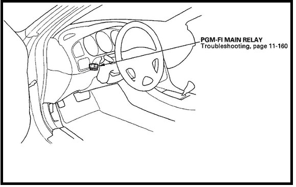
If you have the service manual, it shows the location of the PGM-FI (see photo below), but looking at that there is no way to identify it, where exactly it is and which one it is. If you open the dashboard lower cover (instructions given below) which is below the steering wheel, there a lot of wiring harnesses there, and it is not very easy to locate the PGM-FI main relay.
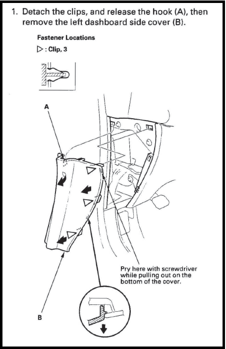
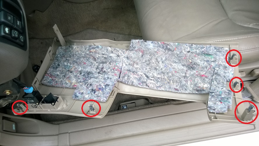
First remove the left dashboard side cover, which is the driver side fuse box cover.
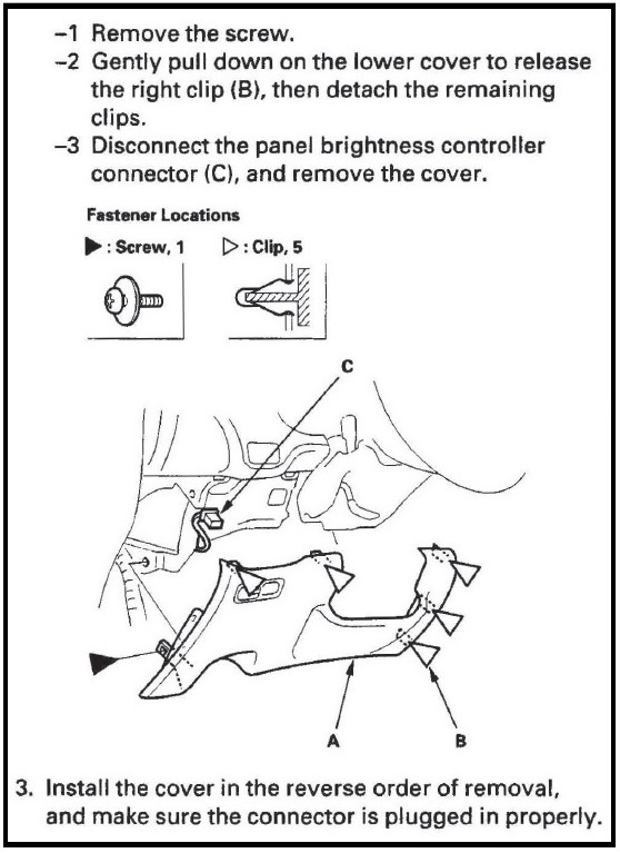
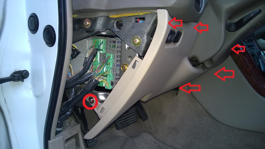
Then remove the one screw and gently pull down to release the 5 clips, marked below.
Please be careful of the wiring harness for the instrument light dimmer, which is connected to this cover
These are the 5 clips.
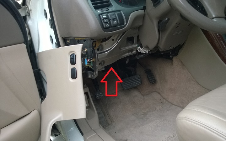
You can either remove the socket for the instrument light dimmer, or leave it connected and carefully lay it to the side.
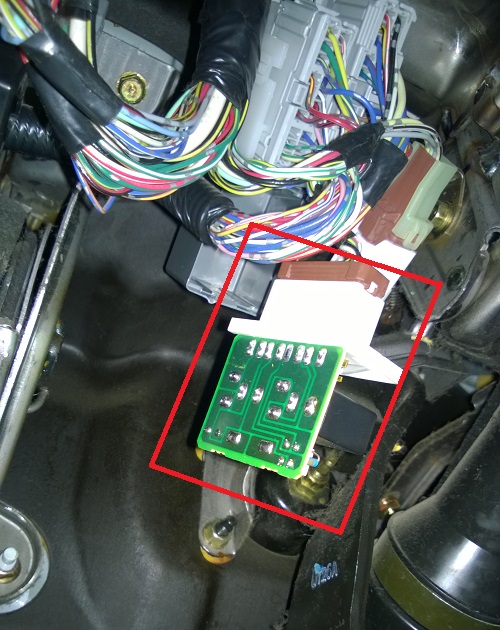
Now this is where the PGM-FI main relay is located. (marked with the arrow)
Once you get under the steering column; you will see a grey box, with a brown socket connected to a white face plate, which is the PGM-FI.
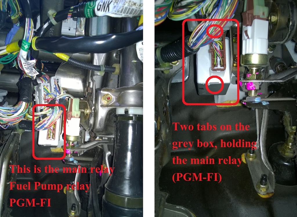
You can either remove the brown socket, and then remove the PGM-FI main relay or remove them together, which is easier, as you have something to hold onto and pull.
The white face plate of the PGM-FI is held inside the grey box with the help of two tabs, one on top and one on the bottom. In the photo below, you can see the one on the bottom, circled red. There is similar one on the top.
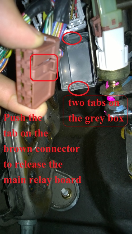
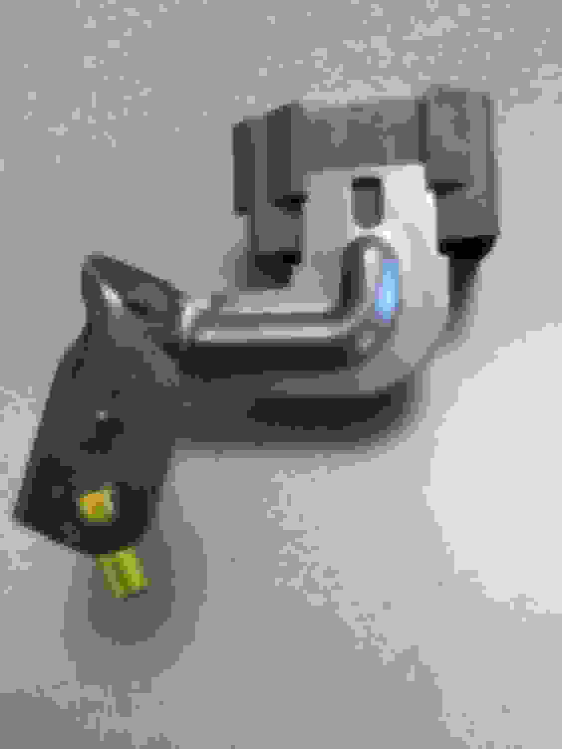
Here is the lock for the brown connector and the grey box with the 2 tabs which hold the PGM-FI in place.
You can use a tiny flat screw driver or something, to pry the PGM-FI out of the grey box, which is a bit tricky, as there is not enough space and there is another big grey wiring harness right next to it. Don’t pull very hard, as there is not enough slack for the wires. Once pulled out you will see the bare naked PGM-FI circuit board. Now you can disconnect the brown harness from the PGM-FI and take it inside for inspection.
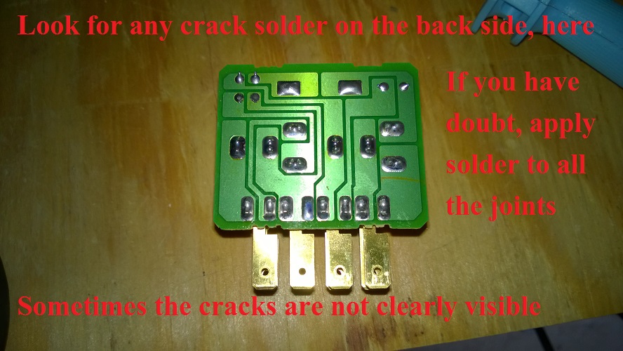
This is where you need to check for cracked solder on all the solder points. The white face plate will slide out of the contacts, and you can keep it aside until you ready to put it back. Remember it is not very easy to see the cracks, unless you have a microscope. I used a small magnifying glass to look at each of the solder joints for any crack or damage. I did not see any crack or damage, but I read somewhere that it would not hurt to add some solder to each joint, which will re-melt the old solder and bind it again, in case there was an invisible crack.
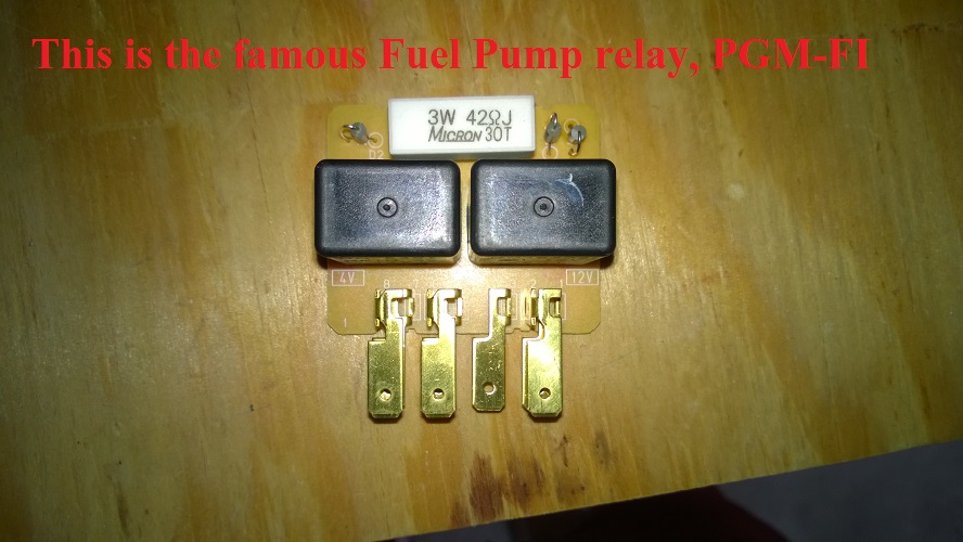
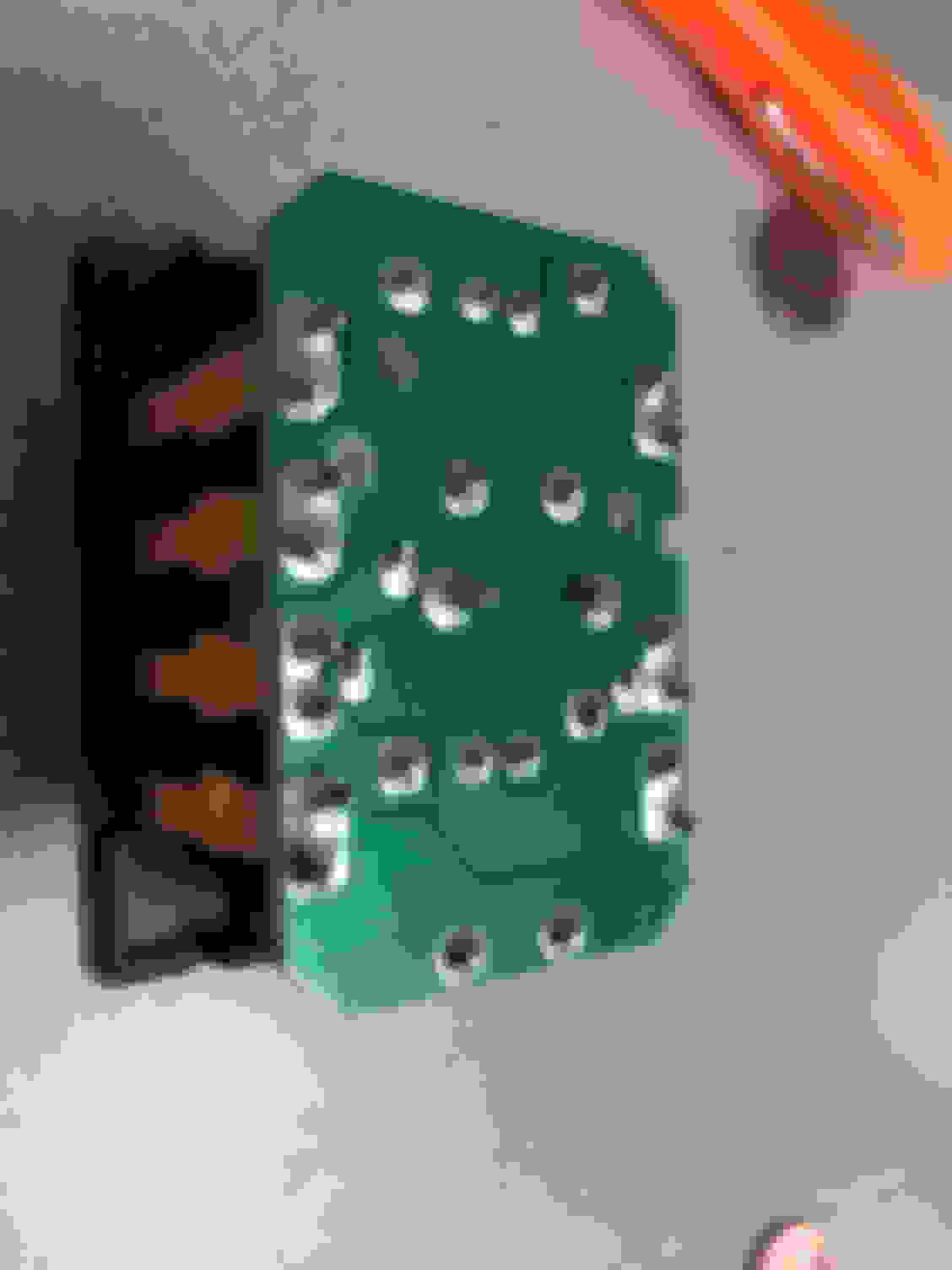
Here is the other side of the PGM-FI, which has 2 relays, a resistor of some kind, and a few diodes. (I’m not an electronic guy). Just check if everything is in place and nothing is broken.
To put it back, it’s the same reverse order. But again I prefer to connect the brown wire harness to the PGM-FI and then slide them together into the grey box. Listen for the click once the white face plate of the PGM-FI is locked in place.
I hope this will be useful for someone like me, who was trying to search where is this mystery PGM-FI.
Cheers.
Also, this is my first DIY on ACURAZINE.
I have got a lot of information from this site, and its users, so it time for payback.
In any small way i can.
i am working on a few project and plan to upload i few more DIY's.
Finally got the brown connector off with the help of needlenose vice grips. I cant really get to the 2 tabs on the gray box. I was able to get my smallest ac delco screwdriver in one corner and it partially cracked the corner of the plastic when I pried it. So I stopped. Mine is a 2001 and is black where the pic shown here is white and there really are no slots where the tabs are showing here.
How do you get the whole gray box housing off as it will wiggle a little where its mounted? I saw on another video where the kid just broke it off the mount and tie wrapped it to hold it back in place. At 58 seconds into the below video, would you pry a small screwdriver into the middle where that tab is by his thumb to slide the whole thing down off the metal mount?
Finally got it out by removing the 10mm bolt holding the mounting bracket on. In the 2nd photo where it shows the 2 tabs on the gray box, you have to unlug the brown connector to the upper right to get to the 10mm bolt. You can clearly see the bolt to the right of that. Used a 1/4 inch drive ratchet.
In order to get the bracket remounted, I had to remove the drivers seat because it is just so tight up under the steering column. I would remove the seat 1st before I start this job. It made it ALOT easier. Plus you get to vaccuum under there and find lots of loose change!
Finally got it out by removing the 10mm bolt holding the mounting bracket on. In the 2nd photo where it shows the 2 tabs on the gray box, you have to unlug the brown connector to the upper right to get to the 10mm bolt. You can clearly see the bolt to the right of that. Used a 1/4 inch drive ratchet.
On my 01 CL-S I was also able to remove the relay by unbolting the mounting bracket bolt using an open-end 10mm wrench. But I did not need to remove ANY trim (or the seat!), as I slid myself upside-down underneath the dash.
Edited to add: We don't care if there are VISIBLE cracks in the solder joints or not, because once the relay is dismounted we are going to reflow the solder anyway. (Plus the cracks are likely invisible.)
Also it has been my mission to spread the knowledge about the many odd symptoms we can get when this relay acts up, so here you go again:
Everything there is to know about your Honda/Acura main relay: How the Main Relay works When the Main Relay goes bad
Hello All and thanks JIGS for the guide on this repair. I followed the instructions and was successful in starting my vehicle again. I did run into an issue though..........
In an effort to fit the fuel relay back into it's plastic housing underneath the steering wheel, I inadvertently brushed the solder joints up against the metal adjacent to the it. This in turn caused a small/brief flash of sparks on the relay. i fitted the relay safely back in the housing and was surprised power was running to the unit at all with the key out of the ignition. I examined the relay and did not spot any damages from this incident.
So now here is my issue:
1. vehicle will not start (not surprising)
2. I have examined the driver side fuses and fuses under the hood (passenger side) and none show to be blown.
Where might the short be and how should i repair it?
Is there a fuse in another location I should check?
Is the best place to check for short circuits the brown harness/clip?
Any recommendations would be extremely appreciated.
Thank you
A lot of people, like me, are not able to locate the PGM-FI main relay, which is also called the Fuel Pump Relay or just Main Relay.
So here is the Mystery relay
I am having some trouble with random starting issues, where the car would crank, but not start. I get random codes each time, which makes it difficult to troubleshot and point out the exact problem. So in one of the forums someone asked me to check the fuel pump relay, and remove the board and inspect it for any cracked solder. I had no idea what he was referring to (not blaming him for that, just lack of my knowledge), until I did my research and found it out.
So what is this PGM-FI? It�s a short form, and a fancy name given by Honda, for Programmed Fuel Injection. Also commonly known as Fuel Pump Relay or Main relay.
This is very common to most of the Honda / Acura and even the location might be in the same place. But please check your manual to verify.
If you have the service manual, it shows the location of the PGM-FI (see photo below), but looking at that there is no way to identify it, where exactly it is and which one it is. If you open the dashboard lower cover (instructions given below) which is below the steering wheel, there a lot of wiring harnesses there, and it is not very easy to locate the PGM-FI main relay.
First remove the left dashboard side cover, which is the driver side fuse box cover. Attachment 46667
Then remove the one screw and gently pull down to release the 5 clips, marked below.
Please be careful of the wiring harness for the instrument light dimmer, which is connected to this cover Attachment 46668
You can either remove the socket for the instrument light dimmer, or leave it connected and carefully lay it to the side.
Now this is where the PGM-FI main relay is located. (marked with the arrow) Attachment 46671
Once you get under the steering column; you will see a grey box, with a brown socket connected to a white face plate, which is the PGM-FI.
You can either remove the brown socket, and then remove the PGM-FI main relay or remove them together, which is easier, as you have something to hold onto and pull.
The white face plate of the PGM-FI is held inside the grey box with the help of two tabs, one on top and one on the bottom. In the photo below, you can see the one on the bottom, circled red. There is similar one on the top. Attachment 46672
Here is the lock for the brown connector and the grey box with the 2 tabs which hold the PGM-FI in place. Attachment 46673
You can use a tiny flat screw driver or something, to pry the PGM-FI out of the grey box, which is a bit tricky, as there is not enough space and there is another big grey wiring harness right next to it. Don�t pull very hard, as there is not enough slack for the wires. Once pulled out you will see the bare naked PGM-FI circuit board. Now you can disconnect the brown harness from the PGM-FI and take it inside for inspection. Attachment 46674
This is where you need to check for cracked solder on all the solder points. The white face plate will slide out of the contacts, and you can keep it aside until you ready to put it back. Remember it is not very easy to see the cracks, unless you have a microscope. I used a small magnifying glass to look at each of the solder joints for any crack or damage. I did not see any crack or damage, but I read somewhere that it would not hurt to add some solder to each joint, which will re-melt the old solder and bind it again, in case there was an invisible crack. Attachment 46675
Here is the other side of the PGM-FI, which has 2 relays, a resistor of some kind, and a few diodes. (I�m not an electronic guy). Just check if everything is in place and nothing is broken. Attachment 46676
To put it back, it�s the same reverse order. But again I prefer to connect the brown wire harness to the PGM-FI and then slide them together into the grey box. Listen for the click once the white face plate of the PGM-FI is locked in place.
I hope this will be useful for someone like me, who was trying to search where is this mystery PGM-FI.
Cheers.
TEARS OF JOY!! Is this the location for a 2009 Honda Civic EX as well?
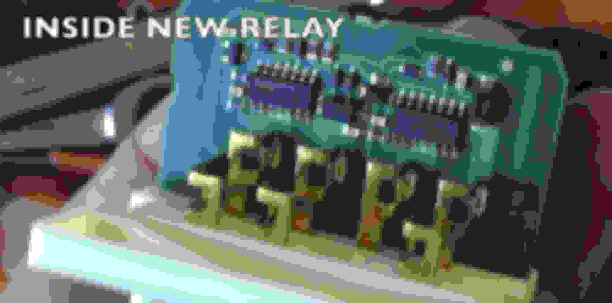
Thank you for this info. I did notice one thing. The new PGM-FI or relay box does not have the large black relays inside. It's all chip based. I honestly didn't think it was going to work but I decided to try it anyway and she started right up. below you will se a picture of the old one's part number incase someone needs that and what the new one looks like.
The pictures in this guide are so helpful! I used a strong LED flashlight and mirror to locate the relay. Once I got the harness off and tested the new part, I was able to work the old part out with the help of a screwdriver, and by moving it left/right. Same thing when sliding the new part on the bracket.
Fixed the starting problem immediately. My problem had gotten progressively worse over the last 3 years, and dealer recommended replacement of the PCM computer, as per service bulletin 01-001 (January 15, 2001).
Btw, part number for 2001 Acura (2nd gen) is 39400-S84-003. I bought a secondary part by Wells Electronics for $50 (Wells 20113 Multi-Purpose Relay).
Is this the replacement part you purchased instead of the OEM Acura part?
Solder joints were fine on my relay. What weren't fine were the two sets of contact points which were worn and corroded. I scuffed them up and the car ran again but the relay is getting replaced. Removing the 10mm bolt that holds the bracket is the way to go and you DO NOT have to remove the seat to accomplish this job. lol. Not even close. This is my 2003 CL-S.
Sharing in hope that it will save someone else some time and worry. TL;DR - thump the relay while starting.
The last few years, about once a year, usually above 3k ft in the NC mtns, my 2001 CL would refuse to start first thing in the morning after sitting a few days. About 10 minutes later, it would start and I�d be a little freaked out, but then the problem wouldn't happen until the next visit to the same mtns a year later. Back home, around 1000 ft altitude, the car always started right up, unless the battery was dead and needed replacing. Batteries tend to last 7-10 yrs for me. i didn't take any action besides internet searches for the issue. it wasn't THAT bad and never left me stranded. King of procrastination here.
Last September, on a very hot day, the car refused to start. After about 15 min, tried again and it started. That was the first and only time being hot was involved with a starting problem. i seldom leave the car outside, it is usually in a garage both at home and work, so seldom gets really hot inside.
This week, the car refused to start while in my garage. This happened for two days. Probably tried to start it 3 times morning, noon, and evening both days hoping the wait 15 min technique would work. it didn't.
Symptoms: The vehicle cranks strongly, but doesn't start. Everyone reading knows that is a common symptom for a bad main relay among other problems it can cause. Wasn't able to hear the fuel pump pre-start to pressurize the lines. All the panel lights are working. Battery is fairly new. The car has never stalled on the road or lost power that wasn't caused by the transmission failing.
Attempted Quick Fixes: Moved the car a few feet, moved the shifter through all the possible settings, swapped the key being used, none of these things helped.
Pulled down a copy of the Service Manual and started reading pg 64: 4-5. Read through the startup troubleshooting steps. I�d already pulled the 2 trim pieces off and looked for the relay, took a bunch of photos, studied them AND this excellent thread to find the relay in addition to watching a few youtube videos. Most of the videos were too generic except 1 which was exactly what i needed for my CL.
The location and tabs are etched in my mind now, easy to find with the correct light.
Back to section 4 of the service manual, Troubleshooting Step 7 has this: Is engine speed above 100 rpm?
NO-Replace the starter, or remove and disassemble it, and check for the following until you find the cause .
Mine didn't move the tach at all when cranking. That's when i really started freaking out. Not hard to replace a starter, but on the Acura it isn't as trivial as on a Ford Escort - the last time I�d replaced a starter.
Something clicked to try one more thing I�d read somewhere before calling for a tow. Thumping the main relay when starting. inserted the key, got on my back, on the floor, took a head-lamp to see and a med-screwdriver, turned the starter and barely tapped the relay with the handle - BAM - started right up. What a relief. That tiny bump had confirmed the issue was the relay.
Seems the same relay may be involved with the transmission problem I�d had a few months ago too. Hope not, that was an expensive fix though some other service items performed were definitely needed too.
Hope this helps someone else. Thump the relay, that 2 min task could diagnose the starting issue pretty quick, though if it doesn't work, that doesn't rule out the relay as the problem.
I'm wondering if the circuit board that is described as possibly having hairline cracks/bad joints is the PGM relay? I see in photos the circuit board and the Grey box, with the Brown socket connected to a white Face plate. You pry the PGM out of the Grey box.
I see on various sites the part listed as: RY423, #39400S84003, and #39400S82A01
And I'm wondering if you are the right person to address this question?
If not would you kindly point me to the right place?
Thanks
GREAT pictures and directions. But could you explain further how to get BOTH (the circuit board & its container) out. Is it held in by a bolt/screw, or some kind of pressure clip?
Some youtube videos mention pushing up and pulling out at the same time. Not a lot of space to work with.
Thanks
Some youtube videos mention pushing up and pulling out at the same time. Not a lot of space to work with.
Thanks
I have seen people claim that this main relay can be slipped off its bracket. In the two times I have had to do this relay replacement, I could never get the relay to slip off.
Instead I used a 10mm socket, on a 1/4 drive extension and 'snaked it up there' to unfasten the bracket via the bolt.
You are correct, there is not a lot of room to work, especially on your back in an uncomfortable position; however, it can be done and you have to persevere.
From the bottom of my heart. I'm a 63 yo young lady and have driven nothing but an acura since my 1990 Legend 2 door coup in 1989. My father bought his first Legend coup in 1986 which was called the 1986 and 1/2. When I flew in for a visit I was allowed (LOLOL) to drive his car. I was sold the 1st time I drove his.
My 2003 TL S was broken into and since I am having a crank no start problem. You might have saved me $$$ in that I can and do learn new things. I'm blessed to be able to read and do as I am told (don't ask Daddy). Thanks again.
Thank you for your excellent example of "Documentation". I wasn't looking for the Pump Relay, but for the Immobilizer Unit, which I thought I had found. The '97 I am working on does not have a screw holding the lower panel on, it turns out to be all clips. Your instructions, however, provided enough clues and got the panel removed. Yes, I had the Immobilizer Unit. I managed to extract it - always scary when you do not know how things plug together.
The 1 remaining key to this car was taken in broad daylight by Aliens and they never beamed it back down after their "experimentations" on it. And, the Magic Red Key had, of course, disappeared over the changes of owners.
Now, I can send the unit into one of the re-programming services and get new keys ... without spending nearly $1000 for the privilege. TY!
I've been having this same problem in a 2004 acura 3.5RL and have been having an extremely difficult time locating the relay. Anyone have any guidance on that model? The diagram in the service repair manual is useless.
I've been having this same problem in a 2004 acura 3.5RL and have been having an extremely difficult time locating the relay. Anyone have any guidance on that model? The diagram in the service repair manual is useless.
You have to move the driver seat back, remove any under dash panel that may be obstructing your view, get on your back and look up.
Look for something that resembles the 39400-SZ5-A01 main relay assembly shown as #14 on the first link below.
I have seen people claim that this main relay can be slipped off its bracket. In the two times I have had to do this relay replacement, I could never get the relay to slip off.
I just did this and the key is using a small flat head screwdriver or even better a small "awl" or "pick" that is pointed and striaght will go right in behind the "clip" and allow the relay to slide right off. Literally took all of 7 seconds. It took me longer to get the damn wiring connector unplugged.
Sliding the new relay and place and plugging it in took all of 5 seconds... VERY easy and straight forward. I would never go though the hassle of unbolting the relay to replace it.
I would never go though the hassle of unbolting the relay to replace it.
Congrats on finding your way of 'skinning that cat'.
IIRC'ly, I did not have the patience, while uncomfortably contorted laying on my back, to dick with the relay clip and found a quicker alternative by unbolting the rely bracket, to each his own.


 [/QUOTE]


