
The JW11 Build, J35A2 Powered MK1 MR2

I would'nt bother with the chambers if they are polished out.
Some temp of high temp coating on the inside of the intake side would probally be a plus.
I'm wondering if anyone coats the manifold, I'm sure that be great for a cooler intake charge.
Some temp of high temp coating on the inside of the intake side would probally be a plus.
I'm wondering if anyone coats the manifold, I'm sure that be great for a cooler intake charge.


Thread Starter
Instructor
Joined: Aug 2010
Posts: 134
Likes: 0
95% finished with this head; 
I went ahead and did some slight modifications to the port shape on the exhaust side. You can see in the picture above that the exhaust ports are directional. Just widened the port by two millimeters on the long turn sides of the outside ports and took one millimeter off of both sides of the center port. I also slightly enlarged the port by removing some material on the bottom portion of the divider starting just above the throat.

I went ahead and did some slight modifications to the port shape on the exhaust side. You can see in the picture above that the exhaust ports are directional. Just widened the port by two millimeters on the long turn sides of the outside ports and took one millimeter off of both sides of the center port. I also slightly enlarged the port by removing some material on the bottom portion of the divider starting just above the throat.
Exhaust ports were a little harder to get nice in the both of the end holes.
On my heads the exhaust ports I did kinda the same.I opened up the the outlet and flattened out the bottom side of the ports but,I did not enlarge in between the centers.
Do you have measuring tools there ?
If so,what is the thickness of the head gaskets ?
Chambers are looking good.How much time you got into them ?
I hate rubbing by hand,My fingers always feel split under my nails for days.
Pain for power,shit we go threw for a couple more hp than the next guy.
Last edited by richardparker; Nov 5, 2010 at 08:22 PM.
Thread Starter
Instructor
Joined: Aug 2010
Posts: 134
Likes: 0
The HG is .7mm thick: two .25mm layers and one .2mm layer if I recall correctly.
I have probably 12 hours in this head so far. The next should go a bit faster I think. Stopped doing the chamber by hand and went with my grinder on it. It has a foot pedal that varies the speed; so it's not as dangerous as, say, a dremel.
I'm leaning back toward doing the ceramic coating on the chamber face. I just need to buy a blast cabinet and guns to get going on that part of te project. Well, airbrush and coatings as well.
No pain, no gain; it will all be worth it soon enough!
Thread Starter
Instructor
Joined: Aug 2010
Posts: 134
Likes: 0
Techline coatings are what I'm leaning toward. And, yes, I am going to do the application myself.
I threw my back out a week ago so I've been missing work and unable to toy with the heads lately. I need to get the other finished so I can have it shaved, mock assemble to check valve clearance, and then clean and coat everything.
I threw my back out a week ago so I've been missing work and unable to toy with the heads lately. I need to get the other finished so I can have it shaved, mock assemble to check valve clearance, and then clean and coat everything.

 ^
^

Thread Starter
Instructor
Joined: Aug 2010
Posts: 134
Likes: 0
A while back I bought a small ball-end carbide burr to make blending the valve seats a little bit easier. It turned out to be a very good investment; I was able to finish the chambers on this second head in half the time it took to do the first. These are both nearly completed and just need some final finishing touches in the ports.

Sorry for the lack of progress and updates guys; I've been too busy and haven't been able to take personal (car) time for a while.
A friend of mine is working on some custom side inlet vents for the project. There will be one on each side; one plumbed directly to the throttle body and the other circulating fresh air in the engine bay. Check that out here.


Thread Starter
Instructor
Joined: Aug 2010
Posts: 134
Likes: 0
Well I did a couple things today.
I dropped the block, crank, main caps, rods, and bare heads off at the machine shop today. It's absurd how much more machine work costs up here in VA compared to Huntsville, where I just moved from. Literally 30% more.
Anyway, I'm having them mic everything in the bottom end to ensure I get the right sized bearings, micro-polish the crank, getting a 3 angle seat cut done, having the heads milled .030", fresh hone, and everything hot tanked.
Then I ran over to HF to pick up a blast cabinet. I need it to start cleaning parts up in general and also prep the pistons for their skirt coating. My air compressor was left in Huntsville so I'll need to find one soon in order to use the blaster.
That's it. Here in a few minutes I'll probably run down and work on smoothing the piston domes. Baby steps.
Thread Starter
Instructor
Joined: Aug 2010
Posts: 134
Likes: 0
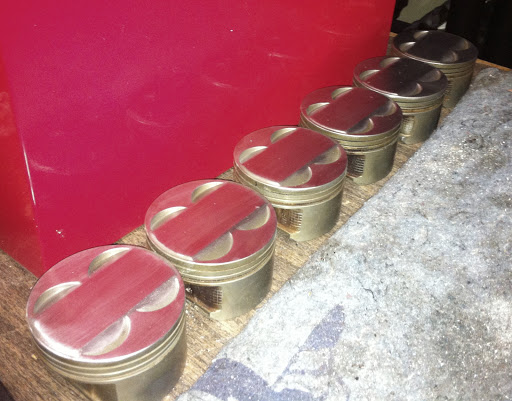
Well I went as far as I am going to go for now on smoothing these piston domes. I'll polish them to a mirror finish once the valve reliefs are cut a touch deeper and I have the dry film lubricant applied to the skirts. The valve reliefs are being cut deeper because I'm milling the head .030". This will make for increase size of the quench pad and hopefully make my 12.6:1 compression ratio a bit safer.
I started these with a carbide burr just to remove the lettering and other markings. Then I graduated from 80 grit to 100, and then on to 180.
For those curious as to why I am doing this: One of the primary causes of detonation is "hot spots" in the chamber. When there are small indentations and protrusions into the chamber, these small bits of metal tend to be hotter than the uniform surface of the piston and chamber. When they get too hot they can prematurely detonate the air fuel mixture.
Also, a mirror polished surface will reflect more heat, i.e. absorb less heat. By obtaining this surface on the chamber face of the head and the piston dome you not only decrease the amount of heat being soaked into the heads and pistons, with those obvious benefits, you increase the thermal energy of the exhaust pulse which can increase scavenging during valve overlap.
Anyway, here they are. I boxed them up and am shipping them back to my machine shop in Huntsville (for above stated reasons) to have to valve reliefs cut deeper.


Thread Starter
Instructor
Joined: Aug 2010
Posts: 134
Likes: 0
I was checking the current base circle size and checking for clearance issues with an extra 2mm of lift: there are none. In fact binding the current valve spring an extra 2.6mm only read an extra 9 inch pounds of torque on my Snap-On techwrench.
I think I'm going to shoot for an extra 2mm of lift and I'll figure out what I'm going to do duration-wise soon enough. I think I might even spec my own valve spring.
This stuff is too much fun.
I think I'm going to shoot for an extra 2mm of lift and I'll figure out what I'm going to do duration-wise soon enough. I think I might even spec my own valve spring.
This stuff is too much fun.
Thread Starter
Instructor
Joined: Aug 2010
Posts: 134
Likes: 0
MEGASQUIRT arrived today!  This is the V3.0 board, MSIII Daughter Board, and the MSX Expansion Board!

Product Info:
Speed-density, alpha-n or MAF for fuelling calculations
16x16 fuel tables in 0.1% steps with true interpolation and movable rows/columns
16x16 spark tables in 0.1 degree steps with true interpolation and movable rows/columns
Wall-wetting transient fuel control for better driveability
On board datalogging to SDcard (max 333Hz sample rate)
Tuning by serial or built-in USB-serial port.
8 channels sequential fuel (hi-z injectors or low-z with external resistors)
2 additional fuel channels (hi-z or low-z)
8 channels sequential spark (logic level output)
6 channels mid current output for small solenoids or relays
2 'spare' conditioned 0-5V analogue inputs (+2 more raw)
Two wideband oxygen sensor input (external controller required)
(Up to eight widebands supported via external data capture)
GM-style stepper idle control
2 and 3 wire PWM idle control
Closed loop idle control
Closed loop mixture control - ideally with wideband
Closed loop boost control
Various boost control systems (gear, time, speed based)
Two stage variable nitrous control
2 step type launch control
CAN communications to interconnect other Megasquirt products e.g. transmission controller
Supports external data capture boards (e.g. for external EGT boards)
EGT data support (with external amplifier)
Staged injection
Dual fuel (e.g. LPG)
Table switching, (mainly for dual fuel use)
Water/Meth injection
Individual cylinder injector trim
Injector phase timing
Individual cylinder spark trim
Support for numerous OEM trigger wheel patterns.
Magnetic (VR), Hall, Opto crank sensor input
Magnetic (VR), Hall, Opto cam sensor input
This is the V3.0 board, MSIII Daughter Board, and the MSX Expansion Board! Product Info:
Speed-density, alpha-n or MAF for fuelling calculations
16x16 fuel tables in 0.1% steps with true interpolation and movable rows/columns
16x16 spark tables in 0.1 degree steps with true interpolation and movable rows/columns
Wall-wetting transient fuel control for better driveability
On board datalogging to SDcard (max 333Hz sample rate)
Tuning by serial or built-in USB-serial port.
8 channels sequential fuel (hi-z injectors or low-z with external resistors)
2 additional fuel channels (hi-z or low-z)
8 channels sequential spark (logic level output)
6 channels mid current output for small solenoids or relays
2 'spare' conditioned 0-5V analogue inputs (+2 more raw)
Two wideband oxygen sensor input (external controller required)
(Up to eight widebands supported via external data capture)
GM-style stepper idle control
2 and 3 wire PWM idle control
Closed loop idle control
Closed loop mixture control - ideally with wideband
Closed loop boost control
Various boost control systems (gear, time, speed based)
Two stage variable nitrous control
2 step type launch control
CAN communications to interconnect other Megasquirt products e.g. transmission controller
Supports external data capture boards (e.g. for external EGT boards)
EGT data support (with external amplifier)
Staged injection
Dual fuel (e.g. LPG)
Table switching, (mainly for dual fuel use)
Water/Meth injection
Individual cylinder injector trim
Injector phase timing
Individual cylinder spark trim
Support for numerous OEM trigger wheel patterns.
Magnetic (VR), Hall, Opto crank sensor input
Magnetic (VR), Hall, Opto cam sensor input

Thread Starter
Instructor
Joined: Aug 2010
Posts: 134
Likes: 0
Cams are in the mail to the regrinder so I have had my thoughts turned toward the lobe designs.
My general thoughts on the design are basically this:
Lobe center angle is essentially fixed; the only possible way to modify it is to slightly move the nose of the exhaust lobe; the middle intake lobe can't be changed on the nose since there is so little base circle material to work with to begin with, and doing so will negate the lift increase that I'm going for.
So LCA can be modified only a touch.
I can take material off of the nose of the small intake lobes since they are going to lose the same amount of base circle material as the big lobes but don't necessarily need the same lift increase. This way I can try and keep the engine responsive at lower rpms by keeping the lift increase low and widening the LCA for the small lobes at the same time.
Because of these changes I will probably wan to bump the VTEC engagement up a few hundred rpms at least.
As for the VTEC lobe; well, Max lift and duration are going to be the main design criteria there. I'll increase the ramp angle (make it close faster) on the downslope of the exhaust lobe so that I won't run into a situation where I have too much overlap, while at the same time tightening the LCA while VTEC is engaged.
This doesn't illustrate the small intake lobes but picture them with a centerline retarded ~5*, opening advanced ~5*, and closing retarded ~5*. Obviously this isn't to scale; if it where, the intake duration would be something like 360* which is obviously not going to happen. Target intake duration would be something between 270 & 290 degrees and lift target would be .45".
Thread Starter
Instructor
Joined: Aug 2010
Posts: 134
Likes: 0
Delta Cam - Bisi of course does regrinds for the J cams as well. They can do your grinds right away. Delta Cam won't have a J cam in hand for a few more days and I'm not sure how long it will be before they have a good "street" profile available; mine certainly isn't going to be something that will be of much use to most users with it being designed to make power from 3500 to 7500rpm.
Thread Starter
Instructor
Joined: Aug 2010
Posts: 134
Likes: 0
Pulled the bottom end parts out of the machine shop this morning when I went in to drop off the intake valves. Everything is nice and straight and within spec. So, I'll order OE Honda bearings in the next few days and get ready to put the bottom end together.
Still need to finish prepping the pistons; talked to the shop back in Huntsville today and they are working on putting a jig together to cut valve reliefs in the 89mm pistons which are too small for their existing jig. Anyone in the area that wants to let go of a decent 10-15 gallon compressor please let me know; I need one in general and the pistons will be at a standstill when they get back until I have one to use with my blast cabinet.
Rods cleaned up, nice and round, and fitted with ARP 2000 bolts:


Crank cleaned and micro-polished:

Block checked, hot tanked, honed, and sprayed:


Still need to finish prepping the pistons; talked to the shop back in Huntsville today and they are working on putting a jig together to cut valve reliefs in the 89mm pistons which are too small for their existing jig. Anyone in the area that wants to let go of a decent 10-15 gallon compressor please let me know; I need one in general and the pistons will be at a standstill when they get back until I have one to use with my blast cabinet.
Rods cleaned up, nice and round, and fitted with ARP 2000 bolts:
Crank cleaned and micro-polished:
Block checked, hot tanked, honed, and sprayed:


