
Yungone501's- Excessive infatuation with the J-series
 07-01-2015, 11:59 PM
#1361
Yeah, they're nice but I mocked them up to a head tonight and the flanges (bell mouths) are both slightly warped so I'll have to get them milled by a friend of mine that works for a local CNC machine shop. Won't cost me anything but it's just the whole point of milling brand new PCD's.
Should have some time this weekend to get them and your long tube j-pipe installed and I'm hoping for a minimum of 20-30hp out doing both together. Can't wait to see and feel the results it makes.
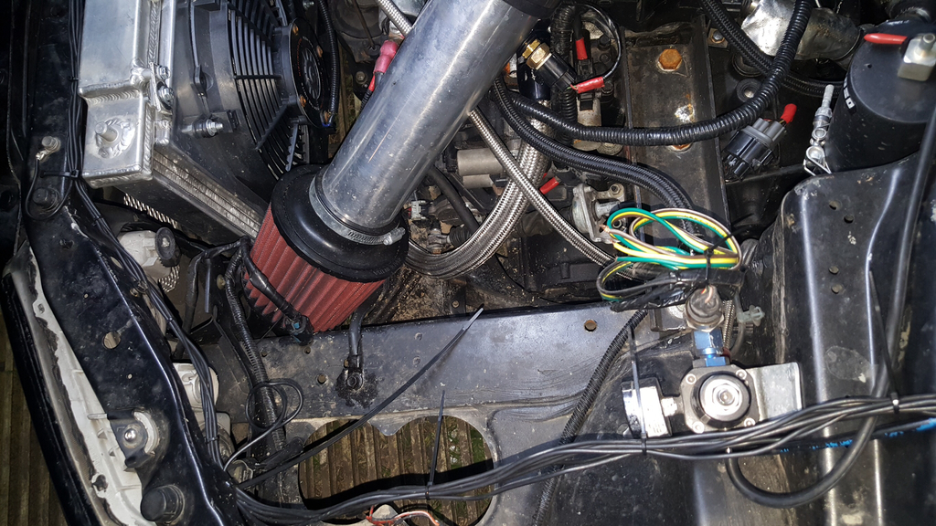
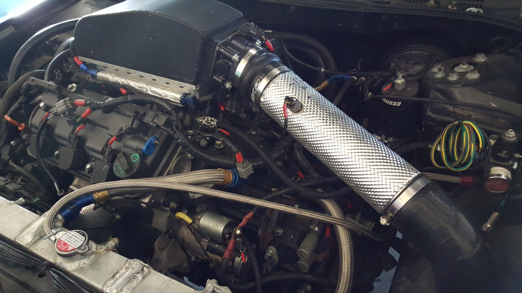
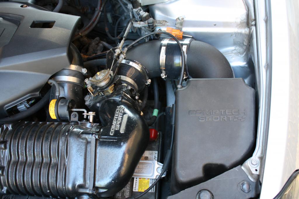
So I made some long awaited changes to the intake tubing and filter here recently to try and lower my IAT's some. Initially when I got the engine up and running, I ended up settling with this location for the filter which has given 10-20 degrees high IAT's then normally seen:
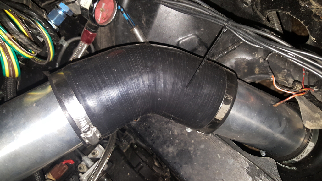
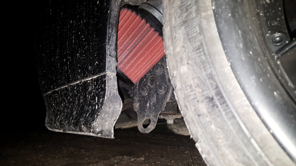
So I ordered some additional 3.25" tubing and another silicone coupler and rerouted the filter to the fender well as shown in the two pics below. This has given me IAT's that are nearly identical numbers as ambient temps so I'm happy with it though I will need to make an enclosure to encase the filter and protect it from water yet still provide somewhat of a ram air effect. So far here's where I'm at:
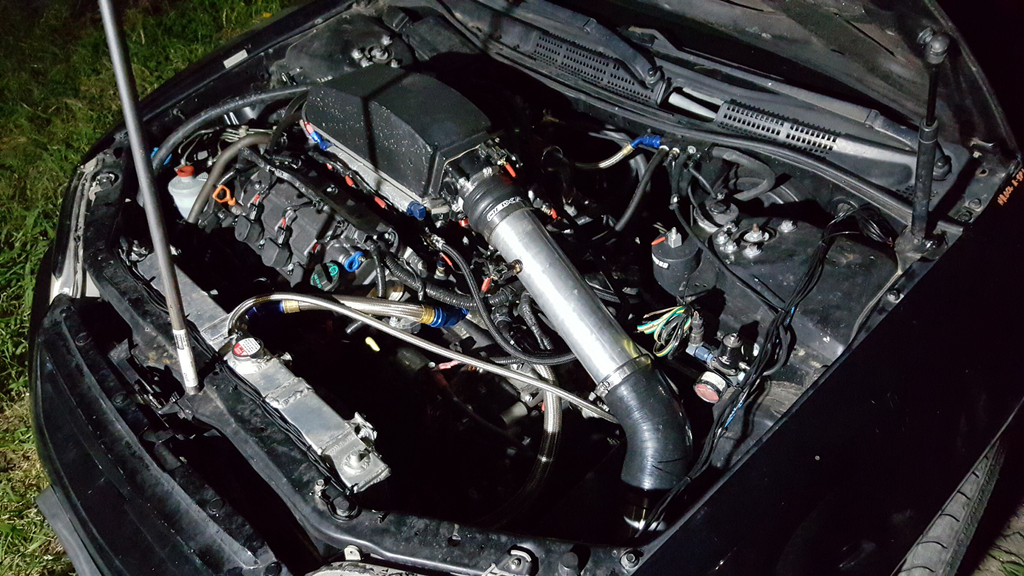
Here's a picture of what was done to the hood for temporary use. Have to give myself props on this one as the hole was made in ONE cut using only a die grinder and a measuring tape. Not bad but I bet I wouldn't be able to replicate this again this well if I tried! Lol
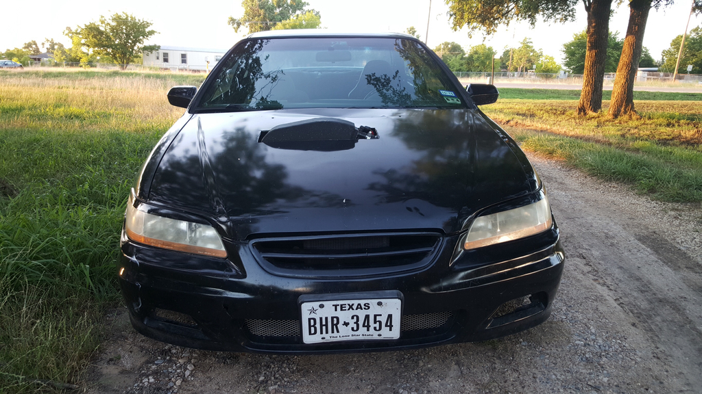
Edit: Also, not that the fender was replaced! $45 used fender....thanks to car-parts.com!
Should have some time this weekend to get them and your long tube j-pipe installed and I'm hoping for a minimum of 20-30hp out doing both together. Can't wait to see and feel the results it makes.
So I made some long awaited changes to the intake tubing and filter here recently to try and lower my IAT's some. Initially when I got the engine up and running, I ended up settling with this location for the filter which has given 10-20 degrees high IAT's then normally seen:
So I ordered some additional 3.25" tubing and another silicone coupler and rerouted the filter to the fender well as shown in the two pics below. This has given me IAT's that are nearly identical numbers as ambient temps so I'm happy with it though I will need to make an enclosure to encase the filter and protect it from water yet still provide somewhat of a ram air effect. So far here's where I'm at:
Here's a picture of what was done to the hood for temporary use. Have to give myself props on this one as the hole was made in ONE cut using only a die grinder and a measuring tape. Not bad but I bet I wouldn't be able to replicate this again this well if I tried! Lol
Edit: Also, not that the fender was replaced! $45 used fender....thanks to car-parts.com!
Last edited by yungone501; 07-02-2015 at 12:02 AM.
 07-08-2015, 02:51 PM
#1363

The following 3 users liked this post by JarrettLauderdale:
 07-10-2015, 06:53 PM
#1365
takin care of Business in
iTrader: (5)
Join Date: Jan 2008
Location: Kansas City, MO
Age: 40
Posts: 30,994
Received 4,732 Likes
on
4,064 Posts
ooomph!!!
fucking A...thats sick!
fucking A...thats sick!
The following users liked this post:
yungone501 (07-12-2015)
07-12-2015, 02:48 AM
#1366
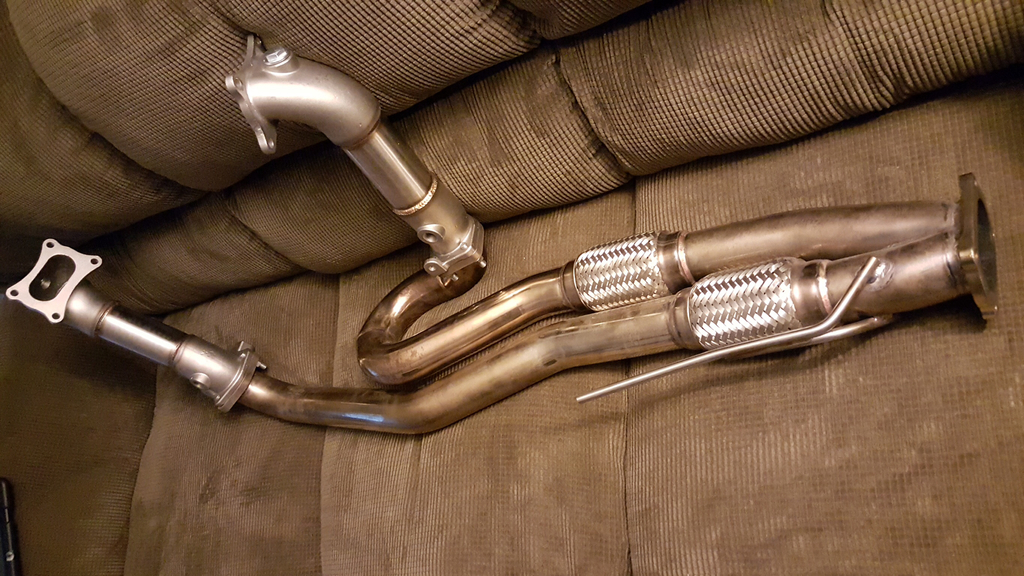
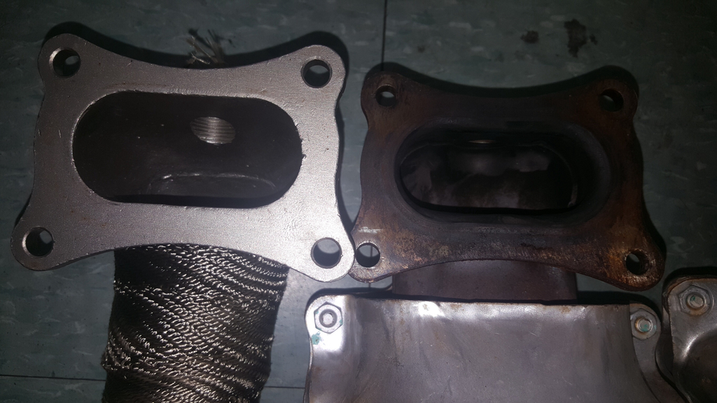
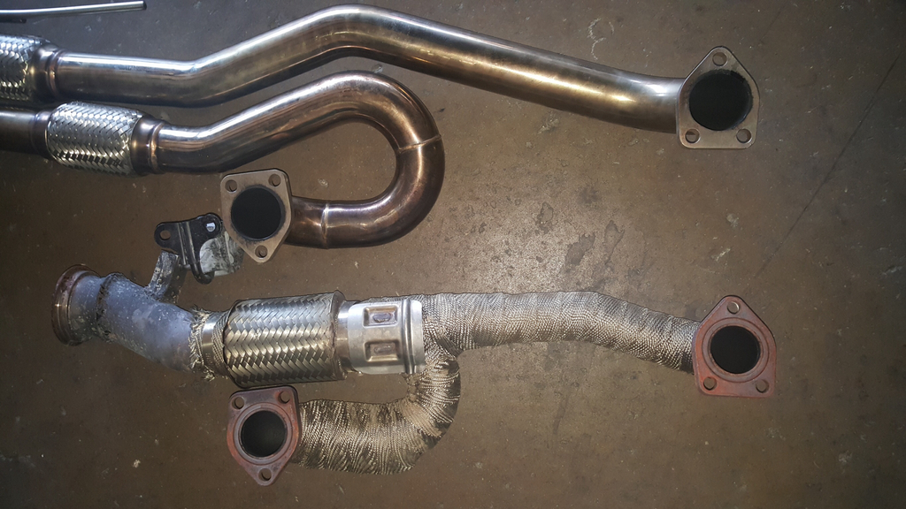
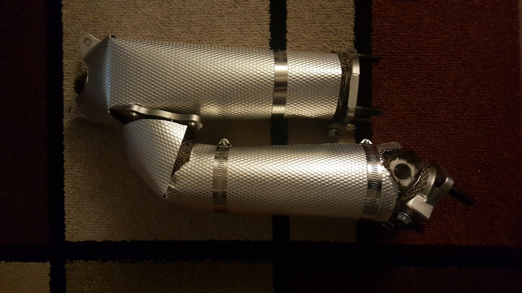
Started on my exhaust install today and took some comparison pics. Pretty large difference between the ID sizes on both the PCD's bell mouth as well as the flanges on the j-pipes. Just to refreshen everyone's memory on what parts are being compared again:
Removing-
2010 TL 3.5 factory j-pipe
2013 Odyssey 3.5 precats
Installing-
RV6 3rd gen TL long tube j-pipe (left side)
Private Label Manufacturing 4th gen TL PCD's (right side)
RV6 on left. Factory on right.
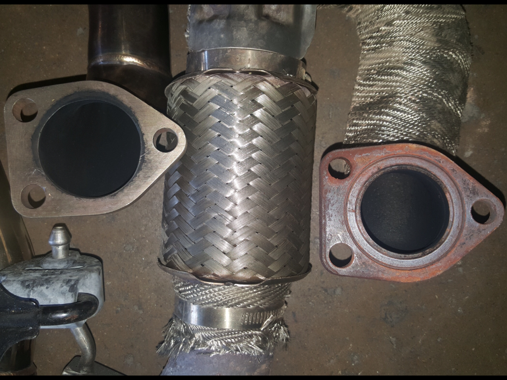
PLM on left. Factory on right.
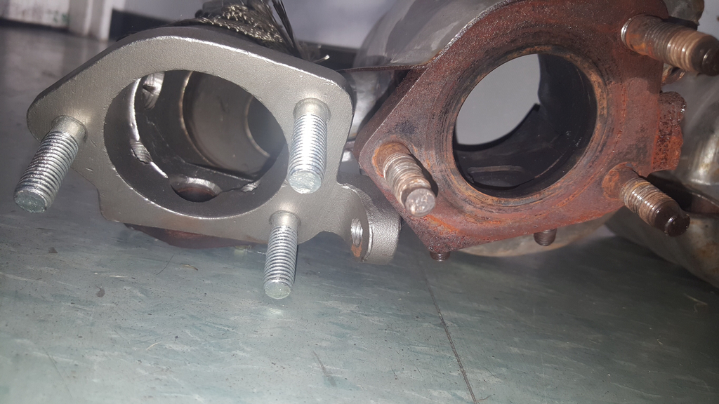
PLM on left. Factory on right.
RV6 on top. Factory on bottom.
Removing-
2010 TL 3.5 factory j-pipe
2013 Odyssey 3.5 precats
Installing-
RV6 3rd gen TL long tube j-pipe (left side)
Private Label Manufacturing 4th gen TL PCD's (right side)
RV6 on left. Factory on right.
PLM on left. Factory on right.
PLM on left. Factory on right.
RV6 on top. Factory on bottom.
07-12-2015, 12:14 PM
#1368
Yeah, but so will a 100 shot of nitrous! 
I was running 13 Odyssey precats on my Accord and PLM PCD's seem to be the same length (from top to bottom) so I don't see why it wouldn't work. However, I would call Richie at RV6 and make sure because I noticed he doesn't have any exhaust components listed for Odysseys. But that could mean none of his current PCD designs won't adapt to the Odyssey or maybe it's just that nobody is particularly interested in modding a minivan in that manner? I do, however, often see lots of exhaust components from aftermarket JDM company's in eBay Japan's site. If you're serious, consider looking there for more options.
I was running 13 Odyssey precats on my Accord and PLM PCD's seem to be the same length (from top to bottom) so I don't see why it wouldn't work. However, I would call Richie at RV6 and make sure because I noticed he doesn't have any exhaust components listed for Odysseys. But that could mean none of his current PCD designs won't adapt to the Odyssey or maybe it's just that nobody is particularly interested in modding a minivan in that manner? I do, however, often see lots of exhaust components from aftermarket JDM company's in eBay Japan's site. If you're serious, consider looking there for more options.
The following users liked this post:
gnuts (07-12-2015)
07-17-2015, 04:31 PM
#1369
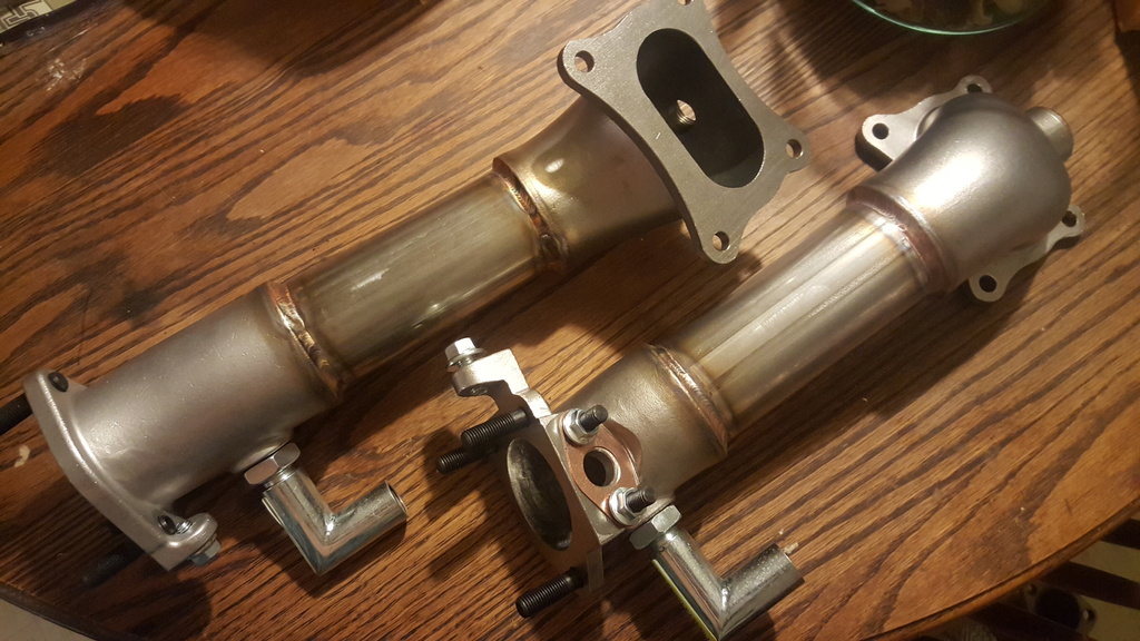
Attention to anyone considering the purchase of PLM PCD's, they did NOT fit and I had to return them for credit. I ended up having to go where I should've went from step 1: to RV6. Already got them and hopefully the install goes smoothly this weekend.
New rv6's
Wrapped and shielded rv6 j-pipe
New rv6's
Wrapped and shielded rv6 j-pipe
07-18-2015, 01:02 PM
#1370
takin care of Business in
iTrader: (5)
Join Date: Jan 2008
Location: Kansas City, MO
Age: 40
Posts: 30,994
Received 4,732 Likes
on
4,064 Posts
holy wrap!
just make sure the welds dont fudge up because of tooo much heat being caught by the wrap!
just make sure the welds dont fudge up because of tooo much heat being caught by the wrap!
07-18-2015, 11:53 PM
#1371
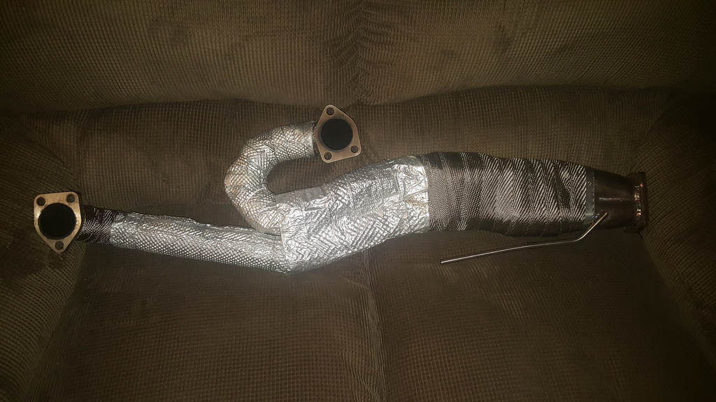
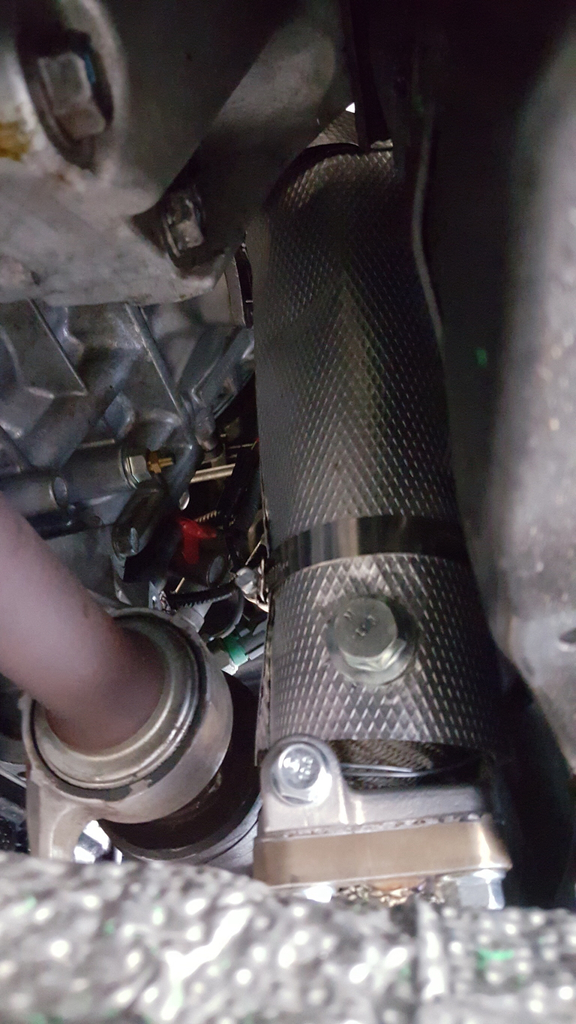
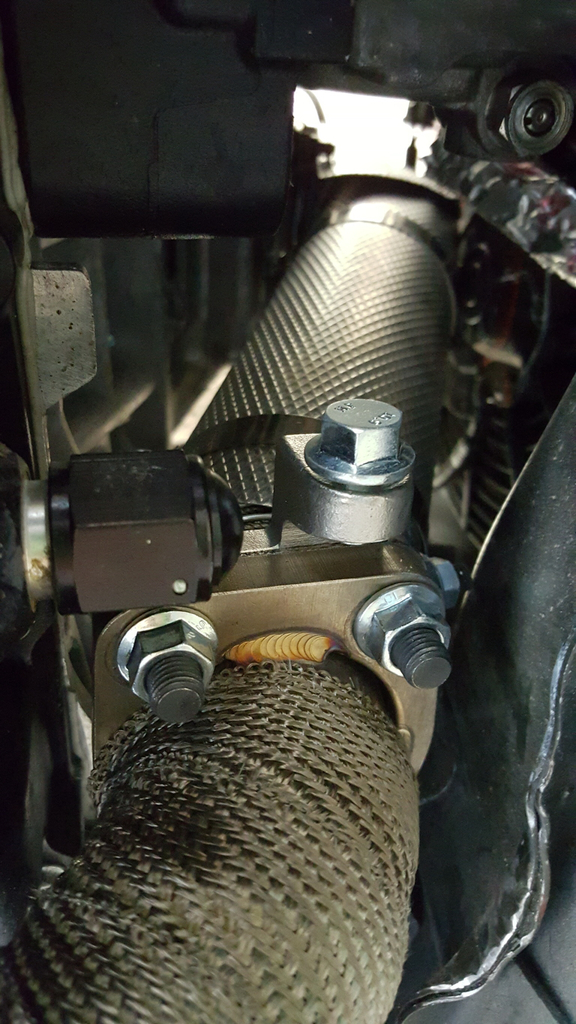
Stayed up late last night and a few hours today to finish up the heat management on the new RV6 precat deletes. I've gotta say, they came out pretty good considering the level of difficulty and because of this, I'm actually glad I ended up having issues with the last PLM precat deletes. Like the RV6 j-pipe, I wrapped in DEI Titanium then made some custom heat shields from some patterned sheet metal I bought online. Because I had to cut out the o2 sensor bungs in the heat wrap, I first spun the PCD's in stainless wire twice concentrating on the bung areas for additional support on the DEI wrap as it begins to fray once cut. Doing this gave me the best look and highest chance of the wrap staying in place after many miles of abuse.
That's it for now. Just wanted to show off some this weekends tweak work on the Accord. Hopefully I'll have time to install the exhaust setup tomorrow and then take some more pics followed up by probably another weeks worth of tuning with Hondata to get things right. Anxiously awaiting this part!

Lmao. I build and drive this car 100% for fun. I'm not saying I don't give a shit about anything on it BUT its the one thing I have that is here just to bring a smile to my face going to or coming home from a hard days work. 
***Btw, for anyone interested, the exhaust setup pictured above will be for sale here probably within a few short weeks. Just long enough to the true potential if this motor being unrestricted and then have Matt weld updated flanges to the turbo manifolds. I'll be asking $500 + shipping so if there's anyone interested in the setup, I'd be willing to accept a holders fee right now of $250. This will include the heat management that's being shown above. Just to clarify again in case it was missed, the j-pipe is originally for a 3G TL and the PCD's for a 4G TL. Both are RV6 products. Thanks!***
That's it for now. Just wanted to show off some this weekends tweak work on the Accord. Hopefully I'll have time to install the exhaust setup tomorrow and then take some more pics followed up by probably another weeks worth of tuning with Hondata to get things right. Anxiously awaiting this part!
***Btw, for anyone interested, the exhaust setup pictured above will be for sale here probably within a few short weeks. Just long enough to the true potential if this motor being unrestricted and then have Matt weld updated flanges to the turbo manifolds. I'll be asking $500 + shipping so if there's anyone interested in the setup, I'd be willing to accept a holders fee right now of $250. This will include the heat management that's being shown above. Just to clarify again in case it was missed, the j-pipe is originally for a 3G TL and the PCD's for a 4G TL. Both are RV6 products. Thanks!***
07-28-2015, 02:04 PM
#1372
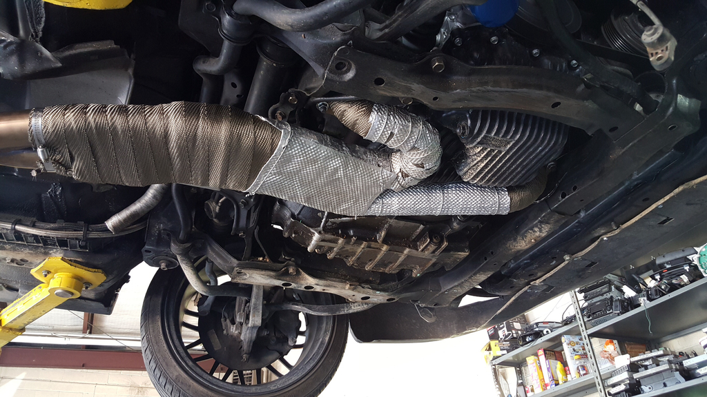
Few shots of the installed exhaust for everyone.
So would anyone believe me if I told you that after having to wait nearly 2 weeks on the exhaust system ordeal, I got into the car so I could start it and check for leaks that the damn thing had an unresponsive pedal!?!?! Crazy! I diagnosed it and found out that the ground from ecm out to the ETC relay wasn't being applied with ignition on so I ordered another module which should be here by tomorrow. These types of problems crack me up really. Just goes to show no matter how many curve balls life throws at you, don't ever assume that you've seen your last one in any situation. lmao
So would anyone believe me if I told you that after having to wait nearly 2 weeks on the exhaust system ordeal, I got into the car so I could start it and check for leaks that the damn thing had an unresponsive pedal!?!?! Crazy! I diagnosed it and found out that the ground from ecm out to the ETC relay wasn't being applied with ignition on so I ordered another module which should be here by tomorrow. These types of problems crack me up really. Just goes to show no matter how many curve balls life throws at you, don't ever assume that you've seen your last one in any situation. lmao
08-23-2015, 12:41 AM
#1373
Sorry about the (what appears to be) the lack of momentum on the Accord but the shop has been the busiest I've ever seen it in all the 12 years I've worked there....not complaining, just informing.
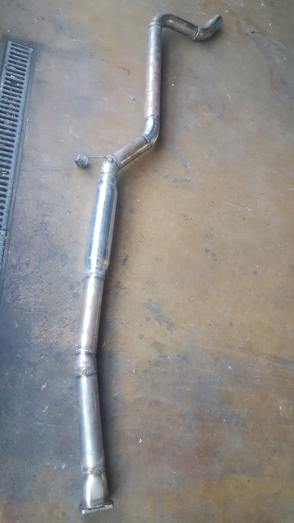
Managed to squeeeeeeeeze in some exhaust work on her today. And yes, I'm trying my luck at fabbing up my own 3 inch exhaust and I have to admit that's it's been going pretty damn good. Went by Smileys Racing in Mesquite, Tx a few days ago and purchased a few 3 inch straights and mandrel 180's then got to work. Decided on using one single Vibrant 18" bottle resonator with no mufflers. It's still very loud but much of that shitty rasp the j-series is well known for was toned down quite a bit. I didn't use stainless because I don't plan on keeping the engine NA very long so I settled for mild steel since my MIG is already set up for the material.
I've included a few shots of the exhaust below for everyone to see. First two pics show the basic structure of the system and as you can see, it's not fully complete but I'm almost there. Due to how low the long tube j-pipe collector hung down, I had to immediately begin heading back upwards to give it road worthy clearance. Thankfully, the j-pipe had two flex pipes preinstalled into each primary which allowed me to raise its collector another 1"-1.5" without stressing the welds so this helped tremendously.
I almost decided on hacking up the 3" dual exhaust that Hickam had fabbed up for the turbo setup which entailed cutting of the Vibrant flange along with roughly 1.5 feet of tubing then rewelding the flange back on but decided not to do this since I would be running the turbo probably by next Spring again. That meant having to either buy a really expensive aftermarket exhaust system (which wouldn't have been true 3") or going with an oem exhaust setup (which would've defeated the purpose of installing the j-pipe & PCD's). So logically, it made sense to put my really expensive yet hardly ever used shop tools to work.
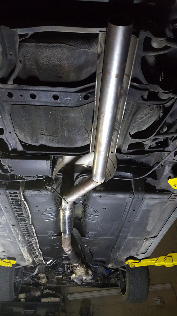
I've got to finish the rear section (which is from the rear subframe) out to the tip. And yes, that was "tip" as in singular. My turbo setup had duals but I figured a single should flow better without the split and also it would've been quite a bit more fab time (probably several hours!) to run dual tips so I went with the single. I misplaced one of the 180 mandrel bends so won't have it finished until next weekend sometime since I have to go back out to Smileys again. As of now, it's all just tacked up and the pieces aren't precision butted against one another....there are several gaps here and there. BUT, its nothing that a MIG couldn't fill in! Once the last few small pieces are cut and tacked up, I'll add maybe two hangers onto the section below the tunnel since it will be assisting in lifting the j-pipe up slightly. Once I have the hangers placed and the setup tacked, I may take it over to a nearby buddy's shop and have him fill in the welds since I don't have my argon/bottle yet and also since there are several small gaps that would require filling in. I don't want to risk blowing out material trying to weld the gaps in since tubing does this rather easily.
Anywho, here's the pics!
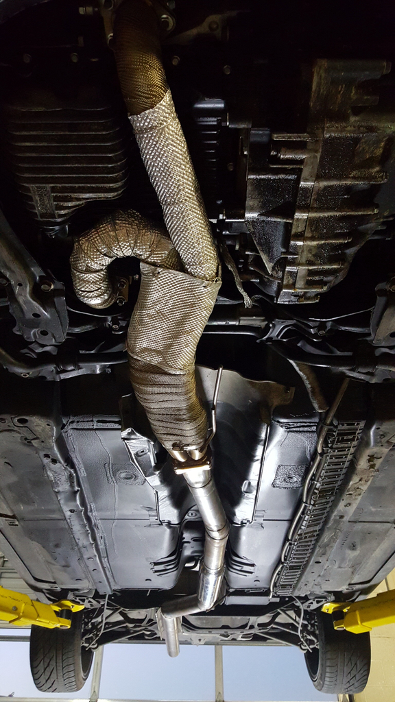
Managed to squeeeeeeeeze in some exhaust work on her today. And yes, I'm trying my luck at fabbing up my own 3 inch exhaust and I have to admit that's it's been going pretty damn good. Went by Smileys Racing in Mesquite, Tx a few days ago and purchased a few 3 inch straights and mandrel 180's then got to work. Decided on using one single Vibrant 18" bottle resonator with no mufflers. It's still very loud but much of that shitty rasp the j-series is well known for was toned down quite a bit. I didn't use stainless because I don't plan on keeping the engine NA very long so I settled for mild steel since my MIG is already set up for the material.
I've included a few shots of the exhaust below for everyone to see. First two pics show the basic structure of the system and as you can see, it's not fully complete but I'm almost there. Due to how low the long tube j-pipe collector hung down, I had to immediately begin heading back upwards to give it road worthy clearance. Thankfully, the j-pipe had two flex pipes preinstalled into each primary which allowed me to raise its collector another 1"-1.5" without stressing the welds so this helped tremendously.
I almost decided on hacking up the 3" dual exhaust that Hickam had fabbed up for the turbo setup which entailed cutting of the Vibrant flange along with roughly 1.5 feet of tubing then rewelding the flange back on but decided not to do this since I would be running the turbo probably by next Spring again. That meant having to either buy a really expensive aftermarket exhaust system (which wouldn't have been true 3") or going with an oem exhaust setup (which would've defeated the purpose of installing the j-pipe & PCD's). So logically, it made sense to put my really expensive yet hardly ever used shop tools to work.
I've got to finish the rear section (which is from the rear subframe) out to the tip. And yes, that was "tip" as in singular. My turbo setup had duals but I figured a single should flow better without the split and also it would've been quite a bit more fab time (probably several hours!) to run dual tips so I went with the single. I misplaced one of the 180 mandrel bends so won't have it finished until next weekend sometime since I have to go back out to Smileys again. As of now, it's all just tacked up and the pieces aren't precision butted against one another....there are several gaps here and there. BUT, its nothing that a MIG couldn't fill in! Once the last few small pieces are cut and tacked up, I'll add maybe two hangers onto the section below the tunnel since it will be assisting in lifting the j-pipe up slightly. Once I have the hangers placed and the setup tacked, I may take it over to a nearby buddy's shop and have him fill in the welds since I don't have my argon/bottle yet and also since there are several small gaps that would require filling in. I don't want to risk blowing out material trying to weld the gaps in since tubing does this rather easily.
Anywho, here's the pics!
The following users liked this post:
teh CL (08-27-2015)
09-20-2015, 01:34 AM
#1374
Alright, so I've done quite a bit since my last update and wanted to catch the thread up a little bit.
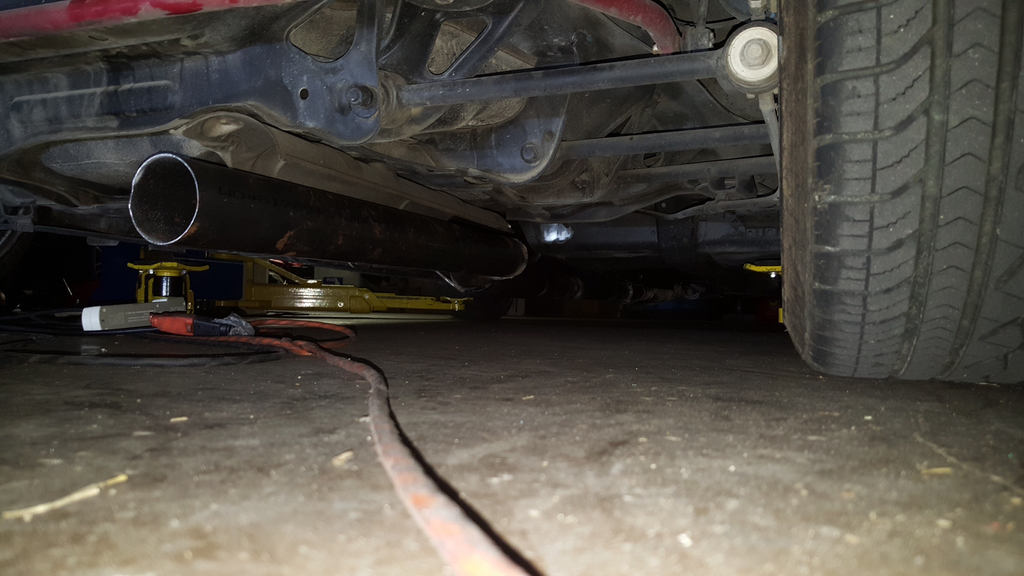
I finally got my exhaust welded up and installed about 2.5 weeks ago. As my last post stated, I used a single magnaflow resonator in an otherwise straight 3" exhaust system. No mufflers, no cats, large diameter tubing made this j35 insanely loud but sounds BADASS. I admit that there's a small area I'm the rev range that has some nasty rasp but it's very small, only between 4k-4.5k. In fact, it's too loud and attracts too much attention from everyone and so I've purchased a magnaflow single in/out stainless muffler which will hopefully be installed sometime next week. Performance has drastically improved and I must say that I was definitely surprised at the gain. My previous 3rd gear WOT runs during tuning use to take an average of 8 seconds. After the complete exhaust system was installed, I managed to shave a full 1.5 seconds off of that (after tuning) 8 seconds which I figured (with some unproved mathematical formulas) netted me around 27hp....again, that's what the math said. Here's a shot of the exhaust right before it was installed:
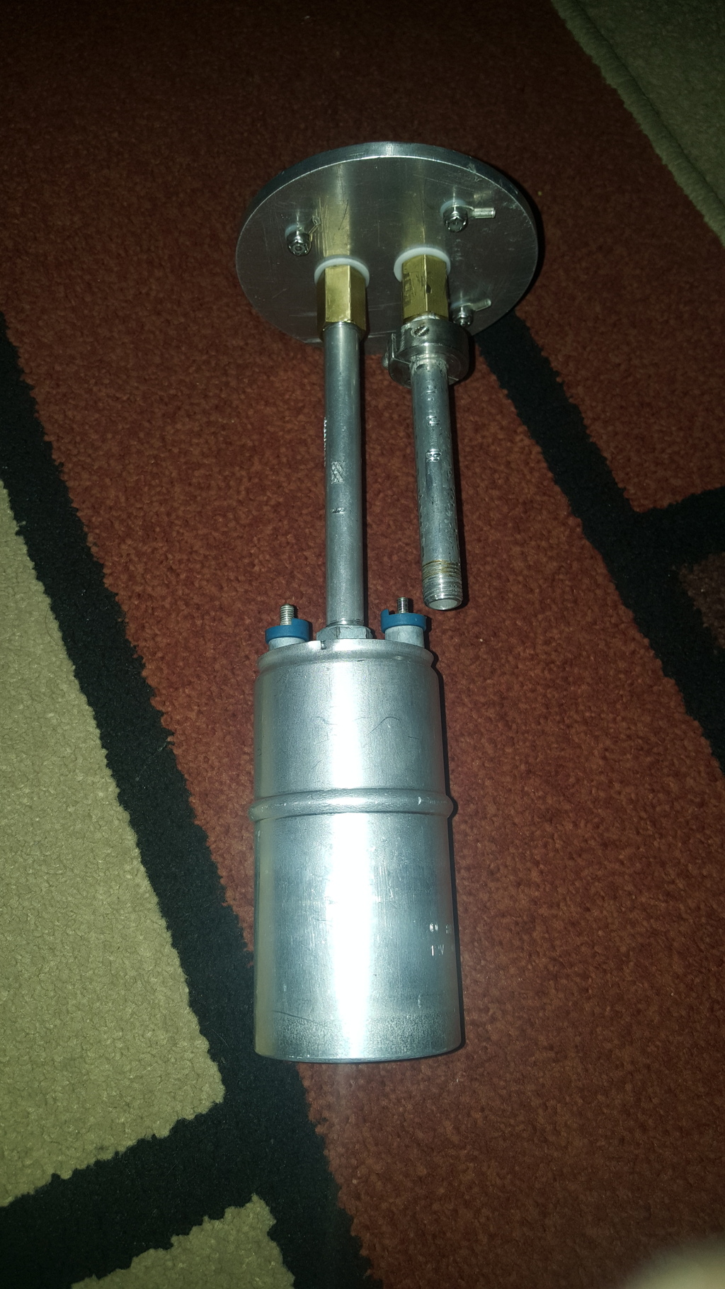
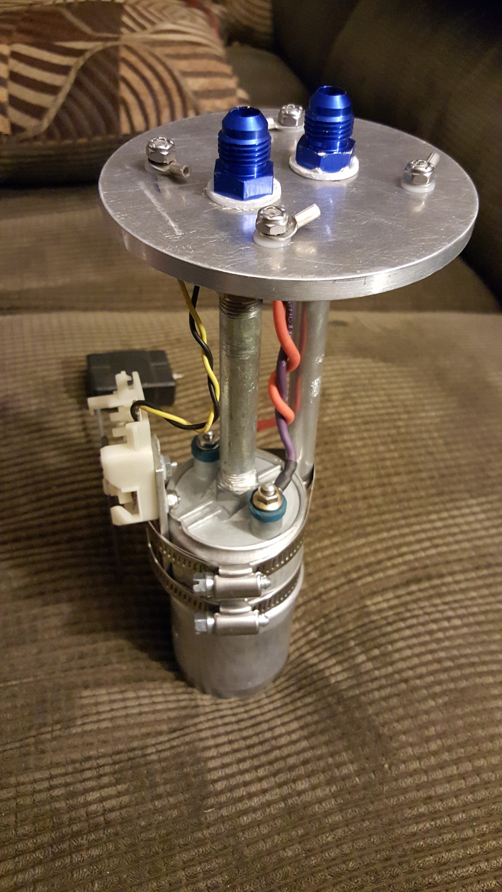
Next on the check list was to finally get my fuel gauge functional. After doing the 08 TL dash swap, I never made it back to this task and now that she's back up and running again, I got to work right away. Because the original fuel assembly was heavily modified to accept a 033 style Bosch pump, this meant fabricating a new pump hanger since the 6g Accord level sender is different than the 3g TL. So then, here's what I came up with so far...
Last thing I have to do is test fit the pump assembly so that I can determine what height the sending unit must be installed at to provide accurate readings. Until next time...
I finally got my exhaust welded up and installed about 2.5 weeks ago. As my last post stated, I used a single magnaflow resonator in an otherwise straight 3" exhaust system. No mufflers, no cats, large diameter tubing made this j35 insanely loud but sounds BADASS. I admit that there's a small area I'm the rev range that has some nasty rasp but it's very small, only between 4k-4.5k. In fact, it's too loud and attracts too much attention from everyone and so I've purchased a magnaflow single in/out stainless muffler which will hopefully be installed sometime next week. Performance has drastically improved and I must say that I was definitely surprised at the gain. My previous 3rd gear WOT runs during tuning use to take an average of 8 seconds. After the complete exhaust system was installed, I managed to shave a full 1.5 seconds off of that (after tuning) 8 seconds which I figured (with some unproved mathematical formulas) netted me around 27hp....again, that's what the math said. Here's a shot of the exhaust right before it was installed:
Next on the check list was to finally get my fuel gauge functional. After doing the 08 TL dash swap, I never made it back to this task and now that she's back up and running again, I got to work right away. Because the original fuel assembly was heavily modified to accept a 033 style Bosch pump, this meant fabricating a new pump hanger since the 6g Accord level sender is different than the 3g TL. So then, here's what I came up with so far...
Last thing I have to do is test fit the pump assembly so that I can determine what height the sending unit must be installed at to provide accurate readings. Until next time...
09-20-2015, 10:23 AM
#1375
I think extending the return fuel down alongside the pump and clamping them together would be a good idea the fuel pushing the pump around could fatigue the nylon washers on the top lid, just my 2 cents, looking good but to be hones I'm just waiting for the turbo to go back on this N/A stuff is just boring after boosting LOL
09-20-2015, 12:02 PM
#1376
I think extending the return fuel down alongside the pump and clamping them together would be a good idea the fuel pushing the pump around could fatigue the nylon washers on the top lid, just my 2 cents, looking good but to be hones I'm just waiting for the turbo to go back on this N/A stuff is just boring after boosting LOL
09-20-2015, 06:35 PM
#1377
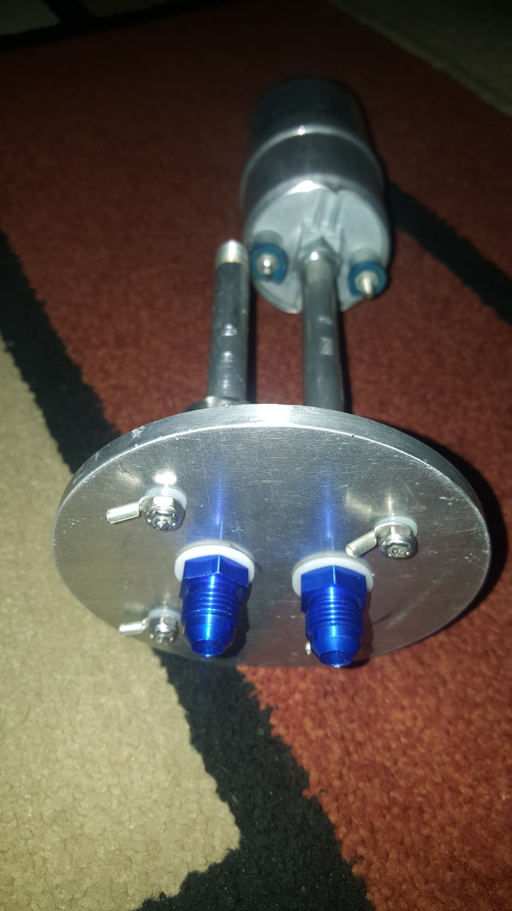
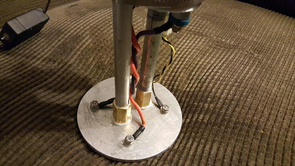
Ok, so here's where I'm at now with the fuel pump hanger. As you can see, I lowered the return line down far enough down to the fuel pump body so that it could be secured with a large hose clamp. Then, I spent some time making an aluminum bracket for the fuel level sender to mount against and then made the same bracket long enough for it to be secured to the pump body using two hose clamps. One of which will be the clamp from the return line and another below it to further secure the level sender bracket. The photo obviously doesn't show the clamps but this will be its final mounting location.

09-22-2015, 01:15 AM
#1378
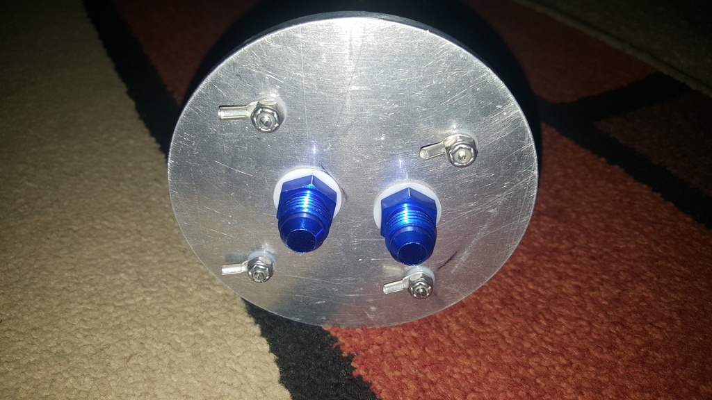
Custom fuel pump hanger complete. Installation tomorrow.
What's next? I've been really contemplating the usefulness of the current intake manifold and its appropriation with the engine. Don't get me wrong, its an absolute wonderful work of art and all...however I believe that it may be impacting my low end powerband due to the loss of the intake manifold runner control (IMRT). As you know, the IMRT is a mechanism designed to switch manifold volumes mid-stride and thereby optimize the engines power in different rev ranges. Because the sheet metal intake is a very large volume manifold design, its primary benefits are seen in higher revs.
I found a great deal on a 2010 TL 3.7 manifold last night on eBay and purchased it right away. Once received, it will be port matched, cleaned, and then installed to see what changes are made down low. If the low end power increase far exceeds that of the sheet metal intakes power up top, then it will remain. And to be totally honest, I think the j37a4 manifold will add tons of power all the way around the powerband. I will keep the sheet metal intake on the shelf and reinstall it early Spring when the boost is back.
The following users liked this post:
yungone501 (10-08-2015)
09-26-2015, 11:13 PM
#1380
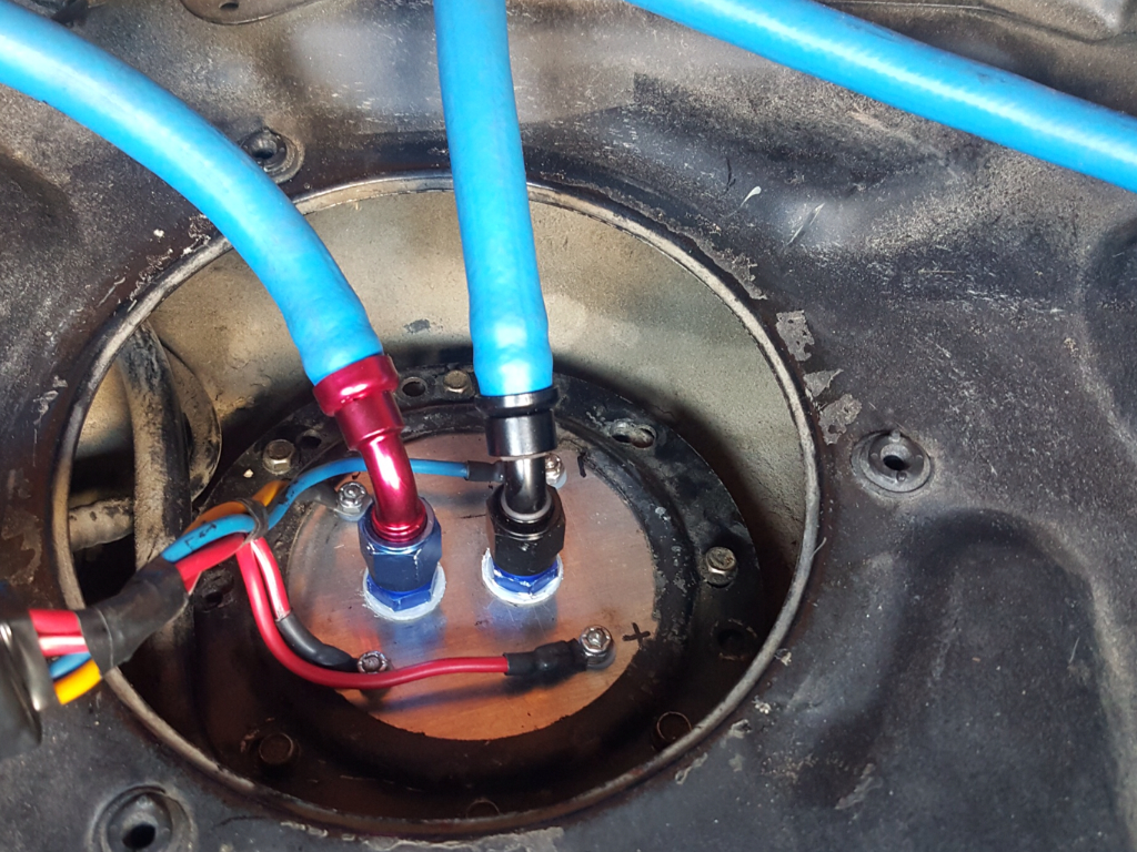
Forgot to post a pic of the fuel hanger installed so here it is. Ended up being a perfect fit and after installing it, I FINALLY wired in my fuel gauge so it's now its operational at last.
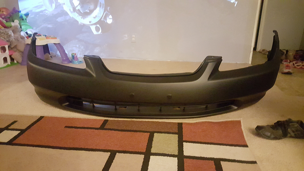
Next on the agenda is prepping the front end for putting the boost back in. Bought me a new front bumper and made sure it was one from a 98 Accord as they have an open area at the top where the grille lays in that's attached to the hood....much like the 2g CL and TL's do in the earlier year models before the grille became integrated into the front bumper covers. And since my 98 Accord has an 02 conversion, this will allow more airflow into the front for the multitude of heat exchangers it's going to have. Also, the lower grille at the bottom will be cut out so that its open and will even drill 1.50" holes directly in front of the radiators for maximum flow. Here's the bumper in its primed form. I will do the airflow mods to it before sending it out for paint obviously. Please excuse the toys piled up in the corner of the room. That's what happens when you have 5 kids.
I'm also going to be getting the Land Rover oil cooler ready for install as well. It will be placed in the long portion of the lower grille of the bumper cover and flow to it will be regulated by a Motul oil thermostat so that the engine doesn't run too cool. The surface area of this oil cooler is very large but with the ever present Summer Texas heat, the more the merrier. Installing this setup allows me to use a remote oil filter as well and all system related lines are sized at -10 AN. The relocated oil filter housing also has 1/8" NPT ports which will enable to install my oil temp and pressure gauges as well. Last but not least, I will be using (not purchased yet) a 5g Accord Mishimoto dual core radiator rather than the single core off brand POS aluminum radiator I'm using now. This should more than cover the added heat from the turbo setup.
09-27-2015, 03:19 PM
#1381
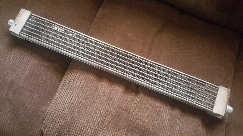
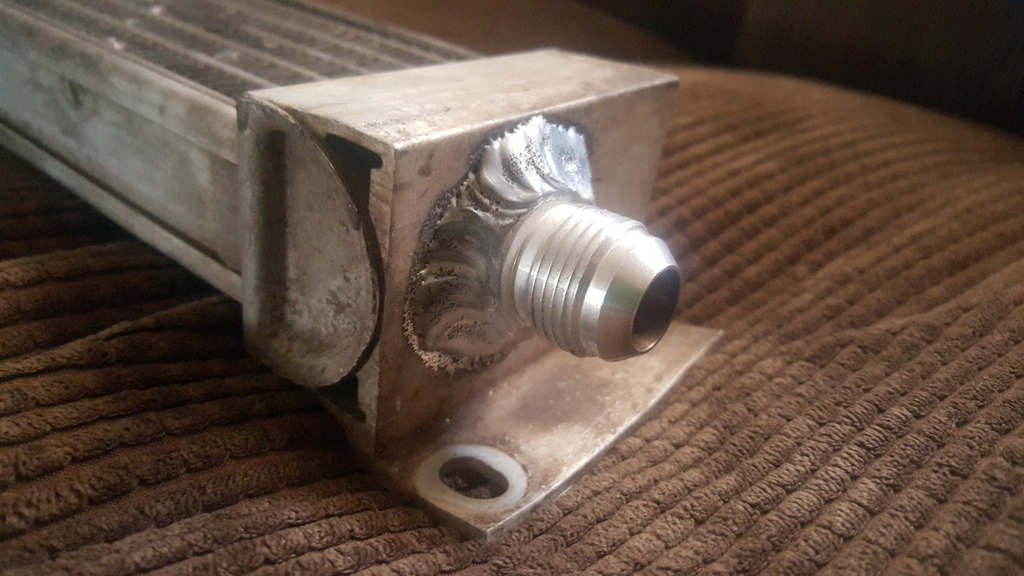
Here's some pictures of some of the newly acquired parts for Accord. First is the oil cooler I explained in the last post. Roughly 26-28" long and has -10 fittings on it. Single pass but its length should be more than enough for adequate heat dissipation. Not to mention, it fits perfectly in the new bumper.
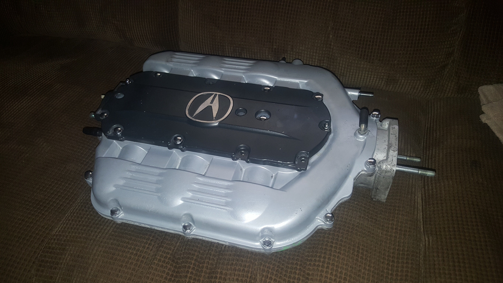
And of course the j37a4 intake from the 09+ TL 3.7. The stock vacuum ports will all be removed and replaced with AN fittings. And when the intake is installed, a thermal gasket to the runners will be its accomplice and help fend off heat. As you might have assumed, the underside of the manifold will be properly heat shielded as well. Again, this manifold will be replacing the custom manifold in hopes of regaining some low end power lost by the single volume plenum.
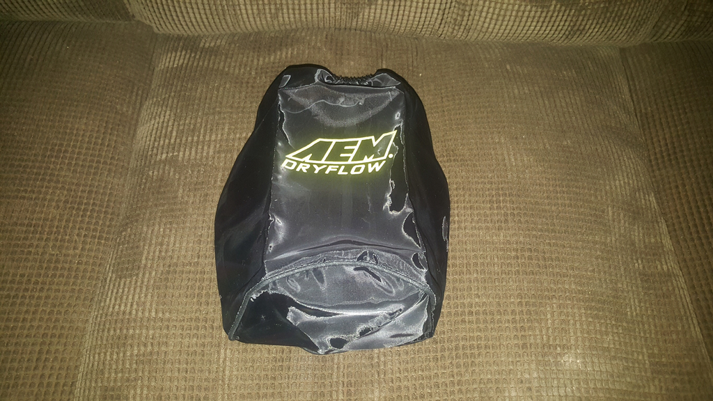
Lastly was this AEM Dryflow which aids in the reduced likelihood of the air filter ingesting water and because my intake setup reroutes the filter to my fender well (which has no splash shield), I figured it would make for some good insurance to say the least. I do plan on making some sort of enclosure around the filter before too long but this should help in the mean time.
And of course the j37a4 intake from the 09+ TL 3.7. The stock vacuum ports will all be removed and replaced with AN fittings. And when the intake is installed, a thermal gasket to the runners will be its accomplice and help fend off heat. As you might have assumed, the underside of the manifold will be properly heat shielded as well. Again, this manifold will be replacing the custom manifold in hopes of regaining some low end power lost by the single volume plenum.
Lastly was this AEM Dryflow which aids in the reduced likelihood of the air filter ingesting water and because my intake setup reroutes the filter to my fender well (which has no splash shield), I figured it would make for some good insurance to say the least. I do plan on making some sort of enclosure around the filter before too long but this should help in the mean time.
10-03-2015, 11:12 AM
#1382
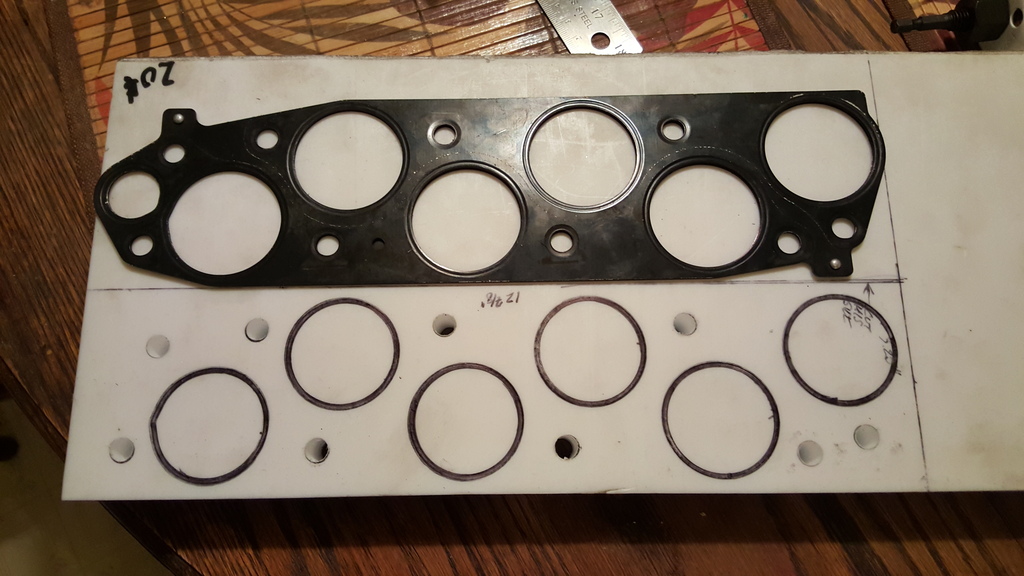
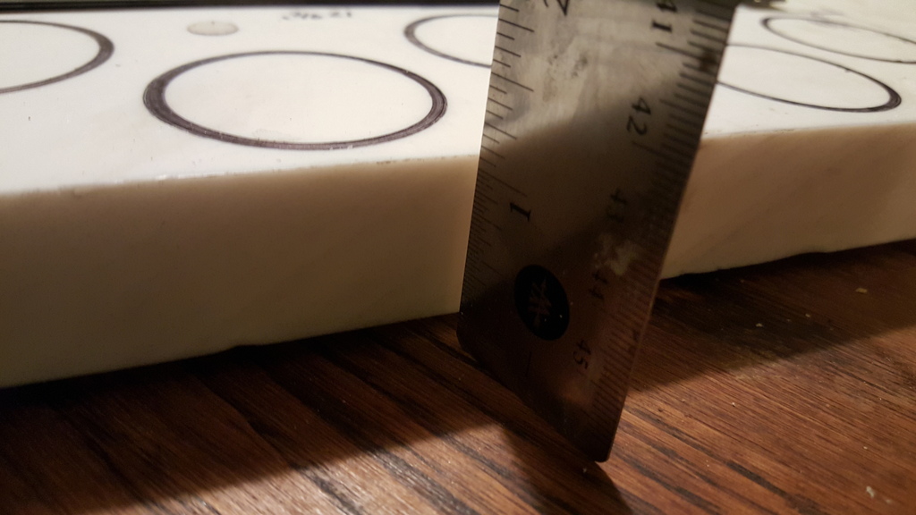
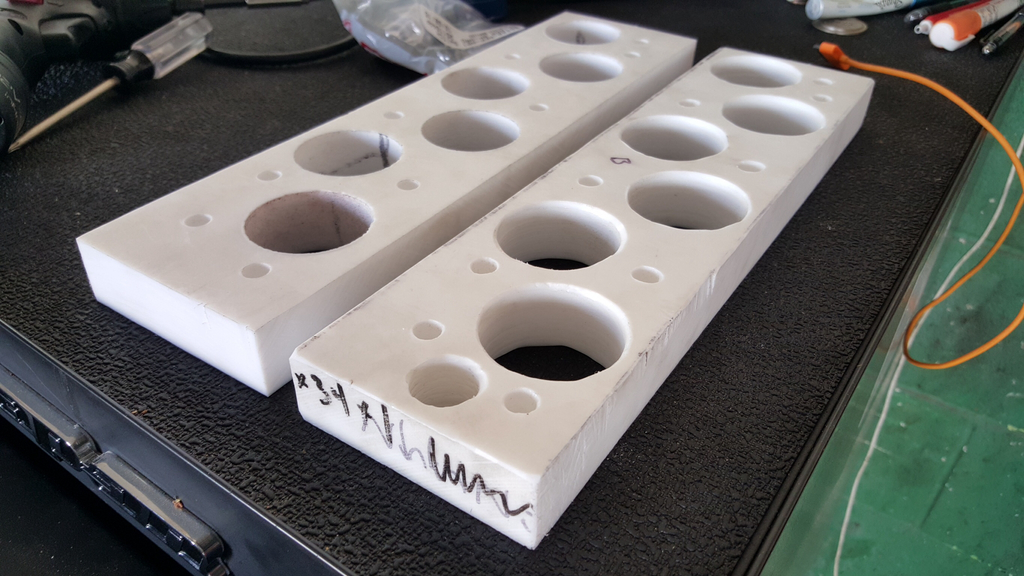
Few pictures that I took of my custom 1" Teflon (PTFE) thermal intake manifold spacer that ill be installing with the j37a4 intake. Got a great deal on some scrap material and decided on making my own masterpiece that laughs at the standard 1/8 standard spacers you buy online. The cool part about all of this is I paid less for the material than one would pay for one pre-made. Lol. For anyone wondering, Teflon is the proper material to be used for thermal spacers as it can handle temps up to 700+ degrees F! Hence the reason non-stick cooking pans are coated with it...even some older engine internals used it for extended service life.
Hopefully I'll have the spacer finished by this weekend so I can have it installed by Sunday night. This will only be possible IF I can somehow find some longer 3.55" M8 bolts to fasten the manifold down to the runners. We will see...
I'd also like to mention that Ive managed to reduce my WOT pulls down another quite impressive (nearly) 1/2 second by tweaking the fuel maps a bit and also eliminating nearly all tip in throttle retard during shifts. Now she hits pretty quick at each gear shift rather than rollllllllling into the next gear. I was amazed at the stupid crap oem tuning does to enhance comfort and drivability and once removed (or modified) can add lots of power. I also changed much my injector overrun cut and restart maps to give some awesome burble on deceleration. I will try and get some video to post up for people to view but man does it sound outright amazing! Im absolutely in LOVE with FlashPro and have been spending some time figuring it all out because this is where the engines true potential is hidden.
The following users liked this post:
m_rgaan (10-04-2015)
10-04-2015, 04:58 PM
#1383
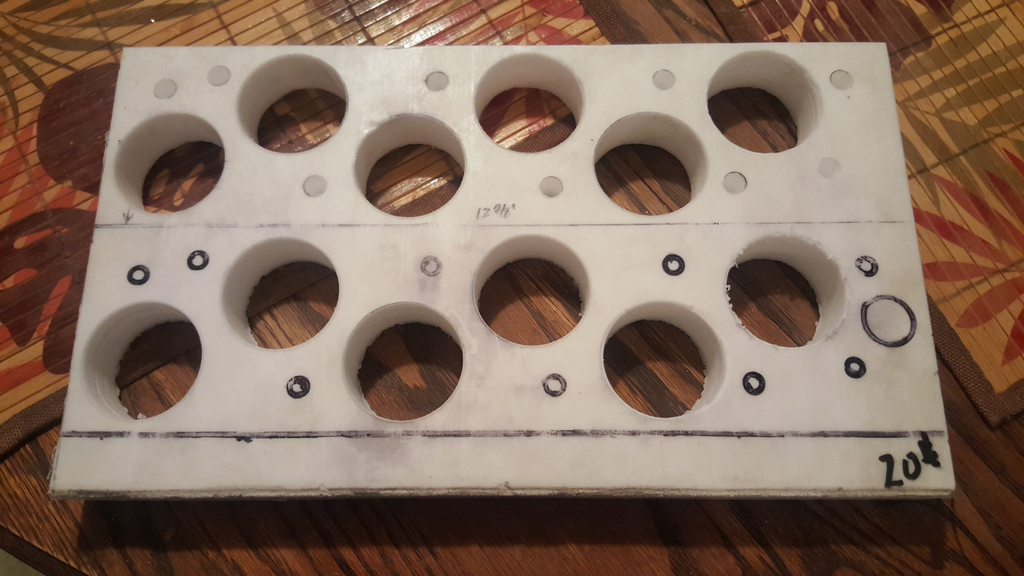
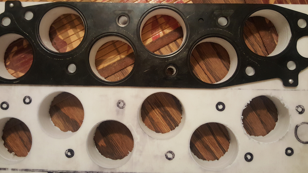
Another update for the thermal spacers. I spent last night using a 1.75" bore cutting out each hole with a drill press and what a pain in the ass it was centering each hole but finally cut them out all perfectly. As you can see in the photos I'm making two spacers: one for me and another for someone else on the forum. Though I wasn't originally planning on making two, I've realized the time involved ensuring things line up perfectly. I'll just say it's not nearly as easy as it sounds or looks!
Just have to finish drilling out the holes for the intake mounting studs on the other spacer, drill out an EGR hole (just on one of the spacers), then separate them as well as trimming any excess material off. Because the other spacer will be used on an engine that will be utilizing EGR, I've decided on pressing in a steel bushing into a slightly oversized EGR bore. Though the spacer can withstand 700+ degrees, I figured its best to play it safe and provide some added assurance with the steel bushing that will be ceramic coated on its ID.
Though the intake won't be installed by this weekend like I was hoping, at least the job was done correctly and to me that's more important.
The following users liked this post:
thisaznboi88 (10-04-2015)
10-08-2015, 09:31 PM
#1385
Got the thermal gaskets done and just in time for the weekend too! My M8x1.25x3.5" bolts should arrive tomorrow afternoon which means the intake will (should) be installed sometime soon within the next 1-2 days. Kind of anxious to see what the stock TL 3.7 intake will do for the motor and hopefully it will all be worth the hassle it's all been.
I'm announcing some unexpected news on the topic of boost. I've decided that the turbo setup will NOT be reinstalled on the Accord. But hang on....let me explain. The reason I've decided this is actually pretty logical. The turbo setup is actually more efficient and designed for roughly 500-600hp levels and because my current motor was not built with any forged parts or "boost friendly" components (other than head studs), it's just not practical to run it using 10lbs or less. Hell, at 10lbs it's not even close to its efficiency level. Having said that, I've decided on selling the turbo setup in its entirety and buy a supercharger instead. At least they are more practical to low boost applications and even allow me to use my current exhaust in just worked so hard at. The blower is a more modest approach which will add to the cars reliability factor and not to mention its decreased complexity as a system will be easier to maintain since my schedule is so damn hectic with being a father of five and a business owner. It's not that I preferred the supercharger route over boost by any means but given my current situation, I must do what is (as I've been repeating) more PRACTICAL.
So anyone who may be interested in the turbo setup, keep an eye out on the black market as it will be posted for sale sometime this weekend.
Found the material on eBay and though it was originally listed at $70, the seller accepted my offer of $40 which btw made it an amazing deal considering the cost of this stuff. And yeah, it makes for a pretty rad mod by cooling the manifold. PM me for more details if you like.
The following users liked this post:
teh CL (10-09-2015)
 10-10-2015, 06:32 PM
#1389
What are you currently running and do you have any pics?
The Prank kit uses an adapter plate of which bolts to the top plate of the manifold so the biggest concern to me would be the requirement of using the j32a2 intake manifold on whichever motor (say a j32a3 or j35a8) the attempt would be made on. This means that if the j32a2 intake was used on a j32a3, an adapter would be required to mount the DBW TB. Then, as you mentioned, determining from there if a pulley misalignment is an issue or not. Possible swap but maybe not an easy for most people on the forum.
Tbh, I'm having so much fun with the current motor in the car I haven't really thought too much about this. Still have all the parts in my garage for the build but until this motor brings boredom, it will more than likely be a while before the short stroke motor is closer to actuality.
I'm gonna say this to everyone here reading this thread now, I've been very happy with what the current motor has become lately since opening up the bottlenecks and also since throwing some very aggressive tuning at it. The power this motor makes is impressive....especially in such a lightweight platform.
10-10-2015, 09:33 PM
#1390
3.5 psi
iTrader: (1)
I would go for the M90 with your motor. I think you would put down some impressive numbers.
I'm running the comptech s/c on low boost. I plan on throwing the 6psi pulley (already have it) on along with a front mount intercooler over the next year or two. We're starting a big house reno soon, so it's on the back burner.
I'm running the comptech s/c on low boost. I plan on throwing the 6psi pulley (already have it) on along with a front mount intercooler over the next year or two. We're starting a big house reno soon, so it's on the back burner.
 10-11-2015, 12:12 AM
#1392
I would go for the M90 with your motor. I think you would put down some impressive numbers.
I'm running the comptech s/c on low boost. I plan on throwing the 6psi pulley (already have it) on along with a front mount intercooler over the next year or two. We're starting a big house reno soon, so it's on the back burner.
I'm running the comptech s/c on low boost. I plan on throwing the 6psi pulley (already have it) on along with a front mount intercooler over the next year or two. We're starting a big house reno soon, so it's on the back burner.
I've always just read so many bad things when it comes to CT and their blowers. Admittedly, it's generally when they're are pushed beyond their design. They are meant to be low boost blowers and people think that overdriving them will bring reliable power but it's usually the opposite. This is because IAT's become so outrageous it offsets the increase in boost.
Again, this is why I'm drawn to the M90.
I'm in complete agreement. As for the A2 block, I don't know how many times I've considered changing back to that design as they could withstand much more boost on stock internals. The newer 2nd gen blocks (such as the j35a8) are just fragile when it comes to their lightened pistons and rods. There are goods and bads to both engines and if Honda hadn't ever went with the IEM (integrated exhaust manifolds) in the newer style heads, I would never look back towards the 1st gen motors. Man did they REALLY f*ck up there. Lmao.
10-11-2015, 12:27 PM
#1393
3.5 psi
iTrader: (1)
The CT kit on low boost is pretty bulletproof, but again it's only on 3ish psi. I will only go to 6psi once the intercooler is on. I've been logging iat temps with the torque app, so I'll be able to measure the effectiveness of the intercooler.
10-12-2015, 11:41 PM
#1394
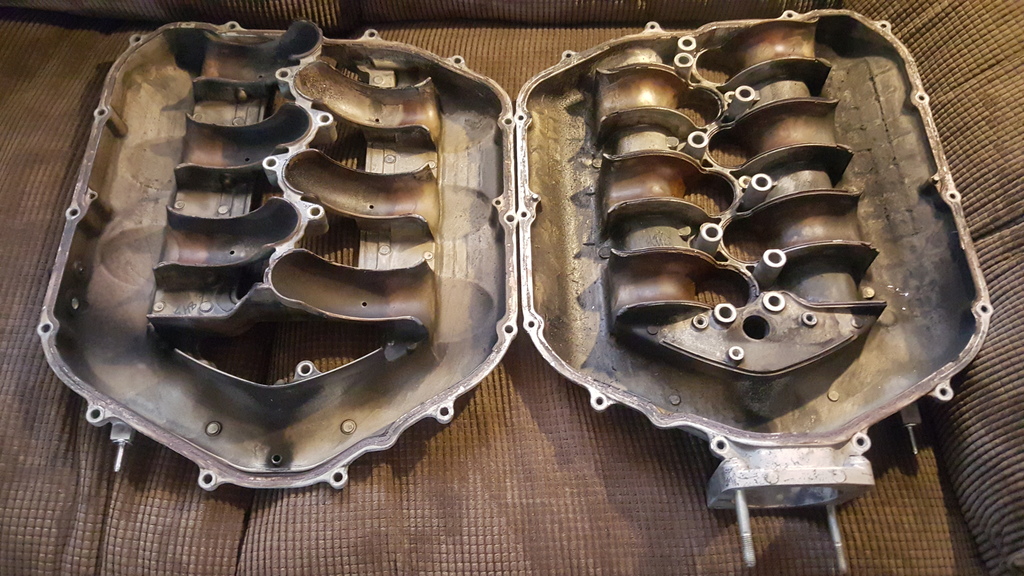
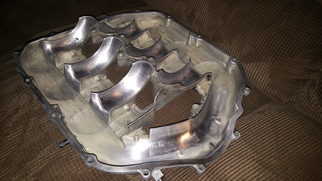
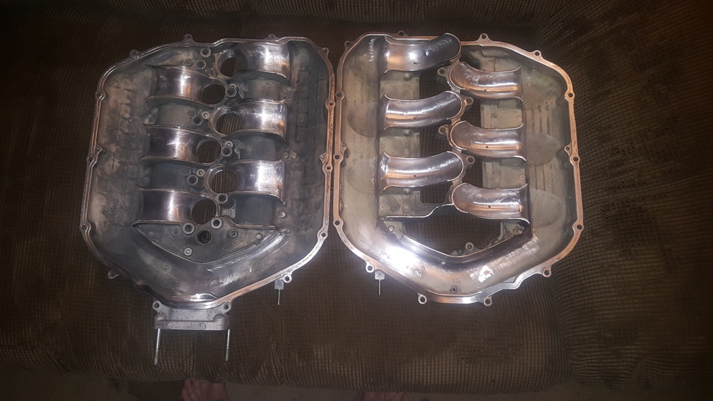
Alright, so I figured since the manifold wasn't installed this past weekend I could at least use the time to my advantage by doing some minor porting as well as some polishing in critical areas. Yup, so I split the case and of course took some photos of the guts for everyone.
Like the older Honda design, it's not an actually variable length runner manifold but more of a dual stage "variable volume" system that has the ability to combine or separate both halves of the manifold at specific RPM of which is set by the ECM. Honda actually did an outstanding job in their design and casting of this manifold because in all honesty....there isn't really much that I can do to make it any better. I'm going to knock a few casting imperfections and 80 grit some of the turbulence zones particularly at the mouth of the intake as well as the entrance of each trumpet. The photos show how it was designed in a two piece fashion and its easy to use your imagination on how things work when the two halves are set together. The volume is a bit bigger than the j35a8 manifolds and almost identical in design with the exception of the throttle body bore itself being much larger as a few other smaller revisions within. The casting porosity is also slightly better than the j35a8 if you ask me but I'm sure that wouldn't be any measurable difference on a dyno by itself.
So this will more than likely be the biggest challenge of the intake is attempting to match the larger displacements volume together with the IMT (intake manifold tuning) actuator and VTEC engagement points. Factory engagement points of these systems are 4000 and 4700 RPM's respectfully on the stock j37a4 BUT the variation between the manifolds volume (3.7) being mismatched to my motors displacement (3.5) will be the largest obstacle of tuning and may even make this intake less than optimal than say another intake manifold from a j35zX engine. However, it's mainly the TB bore size that allures me to this manifold as it will support the horsepower levels I'm hoping to achieve with this all motor setup. Being that the engine has great breathing mods all around, this should allow me to greatly lower both engagement points to an engine speed that will allow ample torque to be produced down low and not give me an enormously high engine speed of where the greatest horsepower levels will be made (below 7000 revs). But again, it's that large manifold volume that will make or break the entire operation. Any way it's looked at, the IMT system and more closely optimized volume of the j37a4 intake will be better than the sheet metal intake that most definitely is NOT complimenting the engines intended powerband. Time will tell....here's the photos.
 10-13-2015, 12:42 PM
#1395
3.5 psi
iTrader: (1)
I looked into the vitviper aftercooler and a barrel style intercooler. I'm going to go with a front mount intercooler as it's simple and I can do some of the work myself. What's your plan for cooling?
10-14-2015, 10:05 PM
#1396
I've always been an advocate of water/meth injection since I've seen the wonders it can perform. And when you compare it advantages to overall simplicity, its an easy choice. Some people say its added complexity or just another risk but that's nonsense. With a few basic switches & sensors, these setups are as reliable they can get. If you ask me, the minimal space a water/meth kit takes up is nothing when comparing it to an intercooler setup.
I've already began brainstorming on a nice little setup that will involve using multiple injection sites and add increased efficiency to the blower I plan on using. Can't wait for this boost to come back ON!
10-15-2015, 10:15 PM
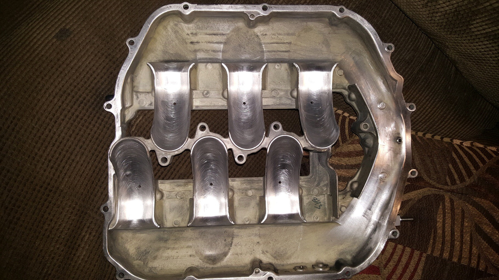
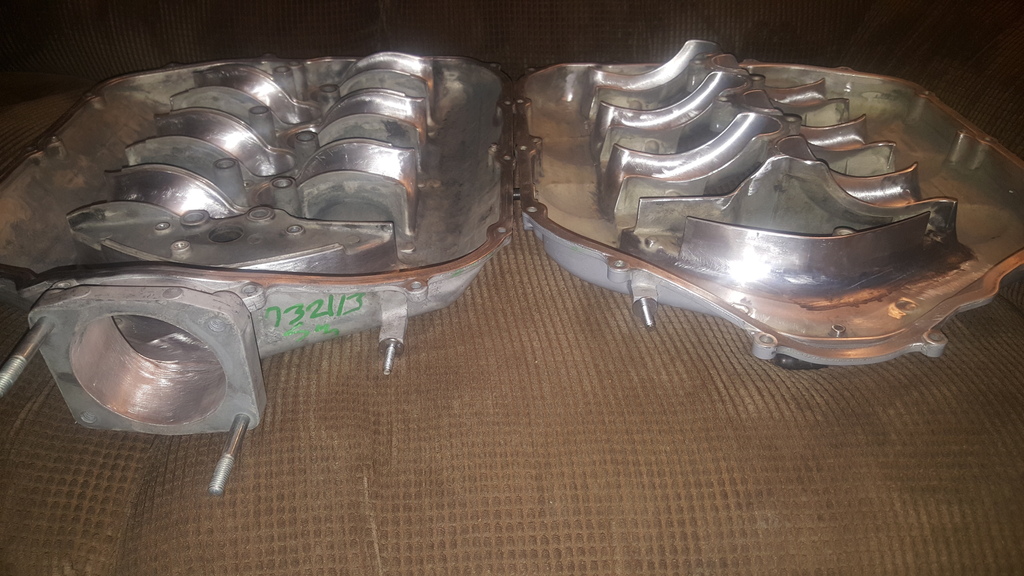
#1397
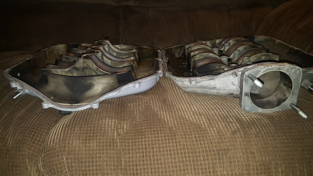
Finished porting the intake. As I mentioned, there wasn't much to improve within the manifold but as you can see I managed to take some casting inconsistencies off of the runners and also the TB mouth while maintaining the necessary roughness to encourage airflow tumble. The runners themselves are, relatively speaking, much shorter than most other production manifolds that I currently see being manufactured so I wanted to try and improve on this direction of keeping the airflow disrupted by creating perpendicular porting motions in regards to the flow direction. If Honda were trying to smooth the airflow I believe they would've made longer runners. This and the fact that even the head intake ports themselves are obviously very focused on strong turbulence to increase burn time.
The halves will be sealed tomorrow but here's what things look like within...
Purchased some true gold heat reflective film that's like $40 sq ft from Pegasus and this will be covering the bottom side of the manifold. To further improve IAT's, I purchased 3" cooling duct which will be force feeding air from a flanged port in the new bumper directly beneath the lower runners to help reduce heat transfer. All of these small, yet effective, cooling mods will be worth a modest 5-10 degrees less on IAT temps.
10-16-2015, 10:58 AM
#1399
Nice work. Think I was able to port mine similarly without splitting it in half. Just fabricated some custom tools to fit in and did a lot of sanding.
After you glue it back together you will need to sand down extra sealer that leaks out.
Not sure if I will ever install mine.
Will you do any hood venting?
After you glue it back together you will need to sand down extra sealer that leaks out.
Not sure if I will ever install mine.
Will you do any hood venting?
10-19-2015, 12:51 AM
#1400
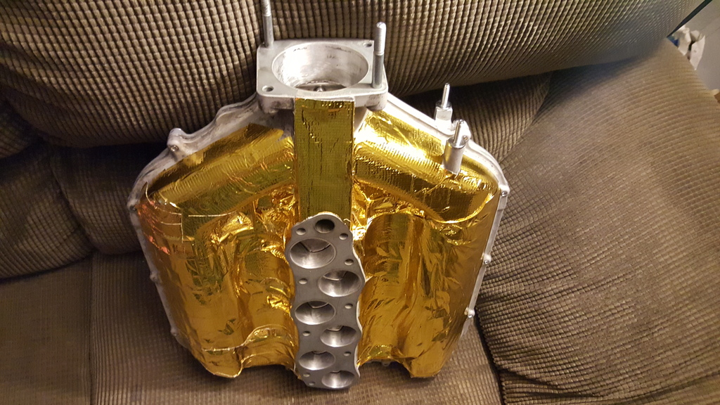
So I managed to get the intake manifold shielded which was essentially the final step (aside from resealing the two halves) in the whole manifold swap before moving onto the installation. I know, I know...it's moving along slowly BUT I'm taking my time since a few more things will be done simultaneously when the intake is swapped. I purchased another hood and got the bumper all trimmed up and so now they're both ready for paint which should be done within the next few days. I decided on replacing the hood since there will be a ridiculously large hole in it now. And because I refuse to drive around with an unfilled hole in the hood, all of these parts must be replaced at once.
The hood will have two large 3.5" holes on either side bored into it so I can have a means of distributing some fresh air into different parts of the motor to aid (as mentioned) in heat removal. These holes will be filled with aluminum trumpet shaped air ducts that I bought on eBay like 5 years ago from a Nascar team. Don't have pics of them currently but I'll try and add them before having the bumper finished.
Nice work. Think I was able to port mine similarly without splitting it in half. Just fabricated some custom tools to fit in and did a lot of sanding.
After you glue it back together you will need to sand down extra sealer that leaks out.
Not sure if I will ever install mine.
Will you do any hood venting?
After you glue it back together you will need to sand down extra sealer that leaks out.
Not sure if I will ever install mine.
Will you do any hood venting?
No hood venting yet. But perhaps later on when the boost comes back on. This was actually an interest of mine that was more or less inspired by some of your work tbh. Loved the work you did to your man...good job.