
navi to video


Three Wheelin'
Joined: Aug 2001
Posts: 1,300
Likes: 0
hey yee wow those pics are crazy....let me get this wiring diagram straight.....for the rgb converter you have:
1. 12 volt power
2. ground
3. red output
4. green out
5. blue out
6. composite out
those are pretty much the only wires we play with right.....?
so we got the 4pdt switch....with 2 ch of inputs and 1 ch of output
output bing the line going to navi display and the 2 input being the info from the dvd rom and the info from the ps2 correct..then the other splices are power to power the rgb converter right? oh yeah where did you put the rgb converter at?
thanks for your help

Instructor
Joined: Jul 2001
Posts: 181
Likes: 2
that's a cool pic...I guess you don't really need those telephone butt connectors if you are gonna connect it directly behind the navi box.
From the pic it looks like you pull power twice ( 1 for the rgb decoder and 1 for the relay switch). Couldn't you use power from the cigarette lighter? So you have to run only 1 wire to the trunk?
From the pic it looks like you pull power twice ( 1 for the rgb decoder and 1 for the relay switch). Couldn't you use power from the cigarette lighter? So you have to run only 1 wire to the trunk?


Burning Brakes
Joined: Jul 2001
Posts: 815
Likes: 0
From: Bay Area
Stan - the 'oops' refers to 'I accidently posted the previous thread without the picture' 
It really is not that complicated...basically there're 4 video wire to play with...and 3 from the RGB box...
I took the picture in a hurry..cuz I was on my way leaving the city...and I won't be back til Jan...but honestly, my knowledge about wire and stuff are very limited, and yet I did it. Give it a start and you'll find that it's not that hard.
Three Wheelin'
Joined: Aug 2001
Posts: 1,300
Likes: 0
Originally posted by yee
Stan - the 'oops' refers to 'I accidently posted the previous thread without the picture'
It really is not that complicated...basically there're 4 video wire to play with...and 3 from the RGB box...
I took the picture in a hurry..cuz I was on my way leaving the city...and I won't be back til Jan...but honestly, my knowledge about wire and stuff are very limited, and yet I did it. Give it a start and you'll find that it's not that hard.

Burning Brakes
Joined: Nov 2001
Posts: 973
Likes: 0
From: tx
Originally posted by yee
Stan - the 'oops' refers to 'I accidently posted the previous thread without the picture'
It really is not that complicated...basically there're 4 video wire to play with...and 3 from the RGB box...
I took the picture in a hurry..cuz I was on my way leaving the city...and I won't be back til Jan...but honestly, my knowledge about wire and stuff are very limited, and yet I did it. Give it a start and you'll find that it's not that hard.
Stan - the 'oops' refers to 'I accidently posted the previous thread without the picture'
It really is not that complicated...basically there're 4 video wire to play with...and 3 from the RGB box...
I took the picture in a hurry..cuz I was on my way leaving the city...and I won't be back til Jan...but honestly, my knowledge about wire and stuff are very limited, and yet I did it. Give it a start and you'll find that it's not that hard.
i already started on phase 2 of my project, which includes relocating the dvdrom player under the passenger seat. yay, talk about fun...oh well, i'll be happy when its all over with...but thanks for all the help
Burning Brakes
Joined: Nov 2001
Posts: 973
Likes: 0
From: tx
why not use CAT5 cabling instead???
this is what i asked myself when i went to home depot to buy the sugg'ed security cable in the instructions. CAT5 is more manageable, IMHO. it was also easier to solder to the factory wires plus i imagine it will be hella easy to solder it to the switch, once i get it.
now i know the wires arent the same colors, but if ur doing this mod to ur car, you should be smart enough to simply write down the new colors compared to the instructions and not mess up...
anyway, this is what i did, and it kinda makes sense...so i'll post it here for ya'll tomorrow, if i dont forget to bring my notes to work..
Burning Brakes
Joined: Nov 2001
Posts: 973
Likes: 0
From: tx
Re: why not use CAT5 cabling instead???
Originally posted by systek
anyway, this is what i did, and it kinda makes sense...so i'll post it here for ya'll tomorrow, if i dont forget to bring my notes to work..
anyway, this is what i did, and it kinda makes sense...so i'll post it here for ya'll tomorrow, if i dont forget to bring my notes to work..
http://dreamwater.org/systek/acuratls/DVDHACK.html

Drifting
Joined: Apr 2001
Posts: 2,272
Likes: 1
From: soCAL
Originally posted by yee
Stan - the 'oops' refers to 'I accidently posted the previous thread without the picture'
Stan - the 'oops' refers to 'I accidently posted the previous thread without the picture'
Burning Brakes
Joined: Nov 2001
Posts: 973
Likes: 0
From: tx
im one step closer to fulfilling the nav rgb...
...conversion w/ dvd player relocation to boot..!!!
http://acura-tl.com/forum/showthread...342#post267342
http://acura-tl.com/forum/showthread...342#post267342

Banned
Joined: Dec 2000
Posts: 503
Likes: 0
From: Tampa, Fl
Hey,
I am thinking about buying a used Navigation system off a 2000 TL. I also have a 2000 TL Non NAvi though. It comes with DVD NAVI, Moniter, and GPS antenna. It dose not come with wires. So would I have to buy the wiring kit from Acura? or dose anybody know where I could get an aftermarket one or make one myself? I was thinking cut the A/C controls and take out the CD changer and mount it there. Or purchase that pice from acura that gose under the NAvi. When I take out my dash and unplug all the a/c controls, will all those wires plug into the back of the NAvi? I would have to make a mold that would go up there right. Prob get Streeteffetcz to make me a mold. What else. I am clueless about the wiring. Then how would I do that thing so i can have it to PLay PS2 and how would I make the voice come out of my speakers? Before I install it should I go ahead and do this mod? HELP!
I am thinking about buying a used Navigation system off a 2000 TL. I also have a 2000 TL Non NAvi though. It comes with DVD NAVI, Moniter, and GPS antenna. It dose not come with wires. So would I have to buy the wiring kit from Acura? or dose anybody know where I could get an aftermarket one or make one myself? I was thinking cut the A/C controls and take out the CD changer and mount it there. Or purchase that pice from acura that gose under the NAvi. When I take out my dash and unplug all the a/c controls, will all those wires plug into the back of the NAvi? I would have to make a mold that would go up there right. Prob get Streeteffetcz to make me a mold. What else. I am clueless about the wiring. Then how would I do that thing so i can have it to PLay PS2 and how would I make the voice come out of my speakers? Before I install it should I go ahead and do this mod? HELP!

Intermediate
Joined: Jan 2002
Posts: 28
Likes: 0
Some In NY Area Needed For This Setup
Is there anyone out there in the NY area ( prefer L.I. ) that is willing to hook up this setup on my 2002 TL??
I have no clue how to take apart a car, especially not to put one together once it is apart!
Any help would be apprecaited, thanks!
I have no clue how to take apart a car, especially not to put one together once it is apart!
Any help would be apprecaited, thanks!
Burning Brakes
Joined: Nov 2001
Posts: 973
Likes: 0
From: tx
Re: Some In NY Area Needed For This Setup
Originally posted by Sarj
Is there anyone out there in the NY area ( prefer L.I. ) that is willing to hook up this setup on my 2002 TL??
I have no clue how to take apart a car, especially not to put one together once it is apart!
Any help would be apprecaited, thanks!
Is there anyone out there in the NY area ( prefer L.I. ) that is willing to hook up this setup on my 2002 TL??
I have no clue how to take apart a car, especially not to put one together once it is apart!
Any help would be apprecaited, thanks!

Burning Brakes
Joined: Nov 2001
Posts: 973
Likes: 0
From: tx
Re: Fly us out there??
Originally posted by Sarj
Cute, real cute.......
Is Texas as close to the NY area as we can get on this list???
Cute, real cute.......
Is Texas as close to the NY area as we can get on this list???
Burning Brakes
Joined: Nov 2001
Posts: 973
Likes: 0
From: tx
Originally posted by Asif2002
dose this work on 99 gps?
dose this work on 99 gps?
http://members.cardomain.com/systeq
yes kids....the car is almost done for now.....i believe i am 2/3's of the way done since we wont be installing a HU anytime soon. or at least until after purchasing home...so let me know what ya'll think so far...
anyone interested in nav conversion will be very interested in cking this out..!!!
Burning Brakes
Joined: Nov 2001
Posts: 973
Likes: 0
From: tx
Originally posted by StanMan
since the avc-rgb1 module is discontinued, people have said the gex tv tuner module works as long as you buy a monitor too.
so is the procedure the same??? got LINKS?
since the avc-rgb1 module is discontinued, people have said the gex tv tuner module works as long as you buy a monitor too.
so is the procedure the same??? got LINKS?
Burning Brakes
Joined: Nov 2001
Posts: 973
Likes: 0
From: tx
Originally posted by systek
while doing my search for the rgb avc, i came across an alpine rgb converter...i didnt take note of the model number, but it got me to wondering..there must be others out there....
while doing my search for the rgb avc, i came across an alpine rgb converter...i didnt take note of the model number, but it got me to wondering..there must be others out there....
http://www.cardomain.com/member_page...164157&page=10
Drifting
Joined: Apr 2001
Posts: 2,272
Likes: 1
From: soCAL
alpine does have this type of convertor as well as jvc (was told they did)...i wonder if it's the same too. i think i might be going with alpine for a complete source system so having the convertor the same would be a nice touch.


Instructor
Joined: Nov 2000
Posts: 126
Likes: 0
Thanks, I was glad to help so many people out with this much needed modificaiton. When I get to the Pearly Gates, I hope He had a Acura with a Video On My Navi install <g>. I wonder how many people have "Video On My Navi" setups now? With over 4,000 viewings (1st and 2nd post) it makes me wonder.
Racer
Joined: Jul 2001
Posts: 415
Likes: 0
From: Downey,CA
sorry i haven't been keeping up with this fourm so i lost alot of what people have said so steve di du make a video based on your conversions i really want to fo this but i'm not sure i would be doing it the right way?
Got da Internet Goin Nutz
Joined: Oct 2001
Posts: 1,997
Likes: 3
From: The Land of Sugar, TEXAS
Thanks Steve!!!!
Steve hooked me up with the original kit as well. It works beautifully!
For audio you DO NOT NEED an aftermarket radio with inputs. There are about three ways to do the audio and get good results.
1. Just get the sony switch (sony xa-39) from crutchfield. The switch goes between the factory headunit and the factory amp. Do a search for it at the streeteffectz forum to see the other happy users of it.
2. Audio Control 4.1 - This works the same way as the sony switch, only it is a million times better. It has two source switiching capabilities and it will also give you EQ capabilities. The only downside is finding a place to put it since it is just like an EQ. If someone here finds a spot please tell me!
3. Use 2 4pdt switches. This option is the cheapest and if you are doing the navi install with one you should understand how to hook it up and make it work.
PLEASE DO NOT USE AN FM MODULATOR THEY ARE F*CKING HORRIBLE AND WILL GIVE YOU BAD SOUND QUALITY DEFEATING THE PURPOSE OF HAVING A DVD.
Make sure you use a dvd player with a HEADPHONE OUTPUT as, it will give you volume control. The headphone output will match the output from the headunit which is crucial to making this work. Do not get the APEX unit from Best Buy, trust me it won't work audio wise.
A great DVD player is the panasonic PV-40. It is the same size as a cd player and will fit in the center console.
Drifting
Joined: Apr 2001
Posts: 2,272
Likes: 1
From: soCAL
relay method
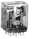
i went to an electronics shop today to get the 4pdt switch, and i looked into the relay method. the switch is on order from another branch, but i also bought the relay components - relay itself and the corresponding socket pad - to investigate that method.
this is the relay
this is a drawing of the socket (as well as the relay pins)
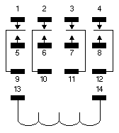
(basically, they look like the components in the pic YEE posted above.)
my question is regarding the switch connection to the relay...connections 13 and 14? do you have to transfer power between the terminals to produce the switching, or is one set always on and you must apply power to one of those terminals to produce the switching?
if anyone knows anything about this, help is appreciated!
this is the relay
this is a drawing of the socket (as well as the relay pins)
(basically, they look like the components in the pic YEE posted above.)
my question is regarding the switch connection to the relay...connections 13 and 14? do you have to transfer power between the terminals to produce the switching, or is one set always on and you must apply power to one of those terminals to produce the switching?
if anyone knows anything about this, help is appreciated!

Pro
Joined: Jul 2000
Posts: 625
Likes: 0
From: so cali
Originally posted by systek
oops, here are my latest nav pix....i just did this last night..almost done.
http://www.cardomain.com/member_page...164157&page=10
oops, here are my latest nav pix....i just did this last night..almost done.
http://www.cardomain.com/member_page...164157&page=10
WOW~~
THANKS for the pics and keeping us updated~~
i really appreciate it...

Burning Brakes
Joined: Jan 2001
Posts: 807
Likes: 0
relay wiring instr
This is based off of your relay diagram. I'll use the left column for example purposes. Pins 9 and 1 are normally connected until you apply power across pins 13 and 14 (connect one to +12v and one to gnd) which energizes the relay and connects pin 9 to pin 5 instead.
So pins 1-9, 2-10, 3-11, 4-12 are normally connected or normally closed (N.C.). When you apply power, pins 5-9,6-10,7-11,8-12 are connected, so these are (N.O).
Pins 1-4 come from your Navi unit. (NC)
Pins 5-8 come from your RGB Video decoder. (NO)
Pins 9-12 go to your Navi screen.
If Pin 14 gets +12v, then connect pin 13 to a SPST switch and then to ground. This switch will select between the inputs.
It doesn't matter whether you wire the inputs R-G-B-Sync in order from left to right, as long as you are consistent with all three sets of wires.
PS: Your diagram doesn't show which one, but you should apply +12v to either pin 14 or pin 13 and gnd to the other one. Test out the relay to see which direction the current must flow to activate it.
I hope this helps. Watching movies on our nav screens sounds real cool. Anyone have this instaled on a TL in SoCal yet?
Drifting
Joined: Apr 2001
Posts: 2,272
Likes: 1
From: soCAL
just mulling over the points before i start...
thanks josh!
here's another thing...do you see the thin brackets, 2 left and 2 right? does anyone think they are possibly related to terminals 13 and 14? meaning, 13 controls the 2 column of pins on the left side and 14 controlling the 2 columns on the right side? somehow i get the feeling that the top row of pins are normally connected to the bottom (or common) row, and when power is applied to BOTH terminals, the connection is made between the middle row and the bottom row. my only doubt is that terminals 13 and 14 are connected with a loop line...meaning it's part of one circuit (and not two like i suspect).
anyone see what i am saying???
or do you think those brackets are meaningless...artistically drawn so the diagram is not cluttered?
Burning Brakes
Joined: Jan 2001
Posts: 807
Likes: 0
Good question Stan,
I am pretty sure that all the rows are switched simultaneously; the right col and left col cannot be controlled independently with that relay. The reason the schematic is drawn like that is just for convenience. Pins 13 and 14 are connected by a swirly circular line to signify that they are the opposite ends of an electromagnet. When you run a current across pins 13 and 14, you power the electromagnet which physically closes the terminals inside the relay. If you put +12v to both pins 13 and 14, the relay will not do activate. If you put Gnd to both pins 13 and 14, the relay will not activate. If you put +12v to one of the pins, and Gnd to one of the pins, the relay will activate. It's the difference in voltage across two points that induces a current flow and current through an electromagnet produces magnetism and magnetism is what closes the relay's internal switches.
I am pretty sure that all the rows are switched simultaneously; the right col and left col cannot be controlled independently with that relay. The reason the schematic is drawn like that is just for convenience. Pins 13 and 14 are connected by a swirly circular line to signify that they are the opposite ends of an electromagnet. When you run a current across pins 13 and 14, you power the electromagnet which physically closes the terminals inside the relay. If you put +12v to both pins 13 and 14, the relay will not do activate. If you put Gnd to both pins 13 and 14, the relay will not activate. If you put +12v to one of the pins, and Gnd to one of the pins, the relay will activate. It's the difference in voltage across two points that induces a current flow and current through an electromagnet produces magnetism and magnetism is what closes the relay's internal switches.
Drifting
Joined: Apr 2001
Posts: 2,272
Likes: 1
From: soCAL
thanks again!
i emailed the company and they said i need to apply power to BOTH terminals...so i will assume the assumptions in my previous post are correct. the top and bottom row of pins are connected normally. when power is applied to both terminals, the bottom row makes the connection with the middle row.
so i guess all i need to do is to wire power to a switch and then onto both terminals.
can those that have done the relay connection confirm this?
Drifting
Joined: Apr 2001
Posts: 2,272
Likes: 1
From: soCAL
this is their reply...
You must apply 12 volts DC to both pins 13 & 14, which is your input
coil.
The rest are all your outputs.
Pins 1, 5, & 9 are one set, 2, 6, & 10 are another, 3, 7, & 11 another,
and
4, 8, & 12 are the other.
There is no switch required to operate this relay.
You must apply 12 volts DC to both pins 13 & 14, which is your input
coil.
The rest are all your outputs.
Pins 1, 5, & 9 are one set, 2, 6, & 10 are another, 3, 7, & 11 another,
and
4, 8, & 12 are the other.
There is no switch required to operate this relay.
Burning Brakes
Joined: Jan 2001
Posts: 807
Likes: 0
Originally posted by StanMan
this is their reply...
You must apply 12 volts DC to both pins 13 & 14, which is your input
coil.
.
this is their reply...
You must apply 12 volts DC to both pins 13 & 14, which is your input
coil.
.
So Stan, report back and let us know which configuration causes the relay to switch. I know you don't care much for USC, but give this Trojan EE a chance.
-josh
Drifting
Joined: Apr 2001
Posts: 2,272
Likes: 1
From: soCAL
i was a little suspicious too...
hey josh, why didn't you say you are an EE to begin with...man, i could have been done already!  seriously, it's just that the parts were not cheap and they could be returned if unopened. but come to think of it, it will be worth every penny just to learn something new even if i don't go this route. again much appreciation!
i let you guys know soon hopefully...
seriously, it's just that the parts were not cheap and they could be returned if unopened. but come to think of it, it will be worth every penny just to learn something new even if i don't go this route. again much appreciation! i let you guys know soon hopefully...
Pro
Joined: Jul 2000
Posts: 625
Likes: 0
From: so cali
how come the intructions from typesdragon, http://www.angelfire.com/super/types...onversion.html
on the back, the wires are soldered differently compared to yee's
first pic is yee's
second is dragon's
which ones right?
on the back, the wires are soldered differently compared to yee's
first pic is yee's
second is dragon's
which ones right?
Drifting
Joined: Apr 2001
Posts: 2,272
Likes: 1
From: soCAL
you see the big loop of red wire...the far left side is the ground point. well, if you follow the circuit track down and to the right, you should soon figure out that strip is all ground...so YEE took the shorter route. as you can see, both ways work. dragon probably chose that spot because it said GND...much easier to identify.