Navi Conversion
 08-04-2004, 02:23 PM
#1
Burning Brakes
Thread Starter

Join Date: Jul 2003
Location: Long Island, NY
Age: 43
Posts: 1,081
Likes: 0
Received 0 Likes
on
0 Posts
Navi Conversion
So I got the Navi converter from the group buy, looks great, everything is very well made but the instructions arent the best for ppl unfamiliar to mobile video. the wiring diagram notes by color of the wire included with the kit, should they just match up to the factory wiring or do I have to track down the pin/wire placement from the factory harness and match it up from there? Anyone tackled this yet? Also there is a RGB/S & RGS/B switch, what the hell is that for? I already installed the power inverter and ran the video wiring and the Blitzsafe is a snap, but I'm too far along to bring this somewhere to get done so any insight would be helpful.
Also I havent taken out the stock navi screen yet so I have no clue what Im dealing with, this may be simple to figure out but I just havent seen whats back there so Im blindly speculating on what problems I may run into.
Heres the picture from the group buy incase that will help:

Also I havent taken out the stock navi screen yet so I have no clue what Im dealing with, this may be simple to figure out but I just havent seen whats back there so Im blindly speculating on what problems I may run into.
Heres the picture from the group buy incase that will help:
 08-04-2004, 02:51 PM
#2
Senior Moderator
Damn, You got it pretty quick.. Maybe take a scan of the directions and I can help you.. I've never messed with the Navi but normally it's pretty basic yellow to yellow but I'm not 100% sure.. I'm just not positive on the factory wiring..
08-05-2004, 11:26 AM
#4
Burning Brakes
Thread Starter
Join Date: Jul 2003
Location: Long Island, NY
Age: 43
Posts: 1,081
Likes: 0
Received 0 Likes
on
0 Posts
Ok so here are the instructions that came with the AV module:

I think its just going to be matching up the colors with the pins on the factory harness I cant really imagine any other way unless I had the factory wiring diagram also.
And heres the pic of the controller, I dont know why its an X

Lemme know what you think, the Blitzsafe will be here today so this is all goin in Fri/Sat
I think its just going to be matching up the colors with the pins on the factory harness I cant really imagine any other way unless I had the factory wiring diagram also.
And heres the pic of the controller, I dont know why its an X
Lemme know what you think, the Blitzsafe will be here today so this is all goin in Fri/Sat
08-05-2004, 01:06 PM
#5
Got da Internet Goin Nutz
OK, I think I understand what is going on here, I am sure others will chim in too.
1. Do your work at the back of the Navi Computer in the trunk. This will be easier than taking out the screen.
2. Take a picture of the harness that was sent with the conversion package. I think this should be as simple as unplugging the harness the back of the computer and plugging it into the provided harness or something like that. Post of picture of the provided harness and we will be able to tell more.
08-05-2004, 01:39 PM
#6
Burning Brakes
Thread Starter
Join Date: Jul 2003
Location: Long Island, NY
Age: 43
Posts: 1,081
Likes: 0
Received 0 Likes
on
0 Posts
The provided harness is a serial cable exactly like the one in the diagram that has 9 exposed wires at the other end to splice into the factory wiring.
the provided serial cable then plugs in to the female side pictured on the side of the module itself.
Im at work now and dont have an image of that and I honestly wont have time to post it tonight so hopefully my description is good enough. If not Ill get an image up ASAP. I think this thread will end up making a great DIY for A-CL members cuz I think a lot purchased this set up in the group buy.
08-05-2004, 03:05 PM
#7
Got da Internet Goin Nutz
OK, I thought this may have been a plug and play unit but I guess not. It is really very simple the way this works.
1. You have to find the 4 wires coming out of the Navi unit in the trunk that correspond to red, green, blue, and sync. If you do a search hear you should be able to find a wiring diagram for the navi that shows what is what. I know there are two plugs going into the back of the Navi unit. All of these wires should be coming out of one plug.
2. Unplug the corresponding plug and pull out the wires as far as you can. The more working space you have in this step the better!
3. You will need to completely cut each one of these wires. Make sure to cut them so you have plenty of room on each of the cut to do the splicing necessary (ie don't make your cut next to the plug that goes into the factory harness.
4. Ajoin the 4 wires coming from the factory plug (navigation computer) to the corresponding wires from pin 2, 4, 5, and 8. I recommend soldering, shrink rap, and electrical tape.
5. Ajoin the 4 wires going to your screen up front with the corresponding wires from pin 3, 6, 7, and 9.
6. The remaining wire is your ground. Ground it!
7. Run the switch, and your power wire up front. Mount the switch where you want it to go. Get your power in the fuse panel. (If you'd like, you can tap the power line that goes into your navi computer instead of running your power up front. You will NOT cut the existing power wire as we did with the rgbsync above, but instead you will just tap it. You can go to radio shaq and ask for a wire tapping sleeve.)
8. You are good to go!
Good luck. This mod is really very simple. Just take your time.
Trending Topics
08-05-2004, 06:05 PM
#9
Burning Brakes
Thread Starter
Join Date: Jul 2003
Location: Long Island, NY
Age: 43
Posts: 1,081
Likes: 0
Received 0 Likes
on
0 Posts
Originally Posted by Jonesi
I'm wondering what's behind the dash and if it's that easy trying to tap back there instead of the trunk.. We shall see..

I cant wire it in the back like that its too far away... I have to consider the AV wire for the PS2 which im mounting under the seat, and later a mobile DVD player in front under the glove box, and I also wired the power inverter nice and neatly under the passenger seat so Im gonna look for the wiring diagrams and take a stab at this. Ill take pictures along the way and post them up here. Wish me luck
08-05-2004, 10:40 PM
#12
Burning Brakes
Thread Starter
Join Date: Jul 2003
Location: Long Island, NY
Age: 43
Posts: 1,081
Likes: 0
Received 0 Likes
on
0 Posts
Shawn S came through with everything. I also think Ive changed my mind about the install and Im probably gonna go with the rear splicing and just run an extension RCA to the back from the blitzsafe. But I still wanna take a look and see if its even possible to do it from the monitor side.
08-05-2004, 11:04 PM
#14
Senior Moderator
Let us know how it goes.. Are there any other directions then the sheet you provided.. I don't have my unit but I'm confused as to why you have so many bare wires... 9 seems like alot considering you'd prob need only RGB and sync..
08-06-2004, 06:56 AM
#15
Burning Brakes
Thread Starter
Join Date: Jul 2003
Location: Long Island, NY
Age: 43
Posts: 1,081
Likes: 0
Received 0 Likes
on
0 Posts
well i have as many bare wires as listed on the sheet for the various functions.
Ex: pin 1 = Ground
pin 2 = Sync
Just like it says on the sheet... the only thing is, the same choices dont seem to be on that factory wiring diagram
Ex: pin 1 = Ground
pin 2 = Sync
Just like it says on the sheet... the only thing is, the same choices dont seem to be on that factory wiring diagram
08-06-2004, 06:58 AM
#16
Senior Moderator
Originally Posted by KissMy_Type_S
well i have as many bare wires as listed on the sheet for the various functions.
Ex: pin 1 = Ground
pin 2 = Sync
Just like it says on the sheet... the only thing is, the same choices dont seem to be on that factory wiring diagram
Ex: pin 1 = Ground
pin 2 = Sync
Just like it says on the sheet... the only thing is, the same choices dont seem to be on that factory wiring diagram
08-06-2004, 07:01 AM
#17
Burning Brakes
Thread Starter
Join Date: Jul 2003
Location: Long Island, NY
Age: 43
Posts: 1,081
Likes: 0
Received 0 Likes
on
0 Posts
well i just emailed the guy we bought it from and sent him the link so Im hoping he'll chime in or maybe we're looking at the wrong one of Shawns diagrams
08-06-2004, 11:02 AM
#22
Senior Moderator
Have not received them.. Once I receive it I will host the directions on here for others to view..
Any update on if my unit and blitzsafe has shipped yet ?
Any update on if my unit and blitzsafe has shipped yet ?
Last edited by Jonesi; 12-17-2009 at 01:41 PM.
08-06-2004, 02:00 PM
#25
Senior Moderator
Originally Posted by KissMy_Type_S
When he says behind the Navi is he talkin about the monitor or the brain in the trunk
08-06-2004, 03:35 PM
#26
Registered User
if you want to do if from behind the screen it's easy
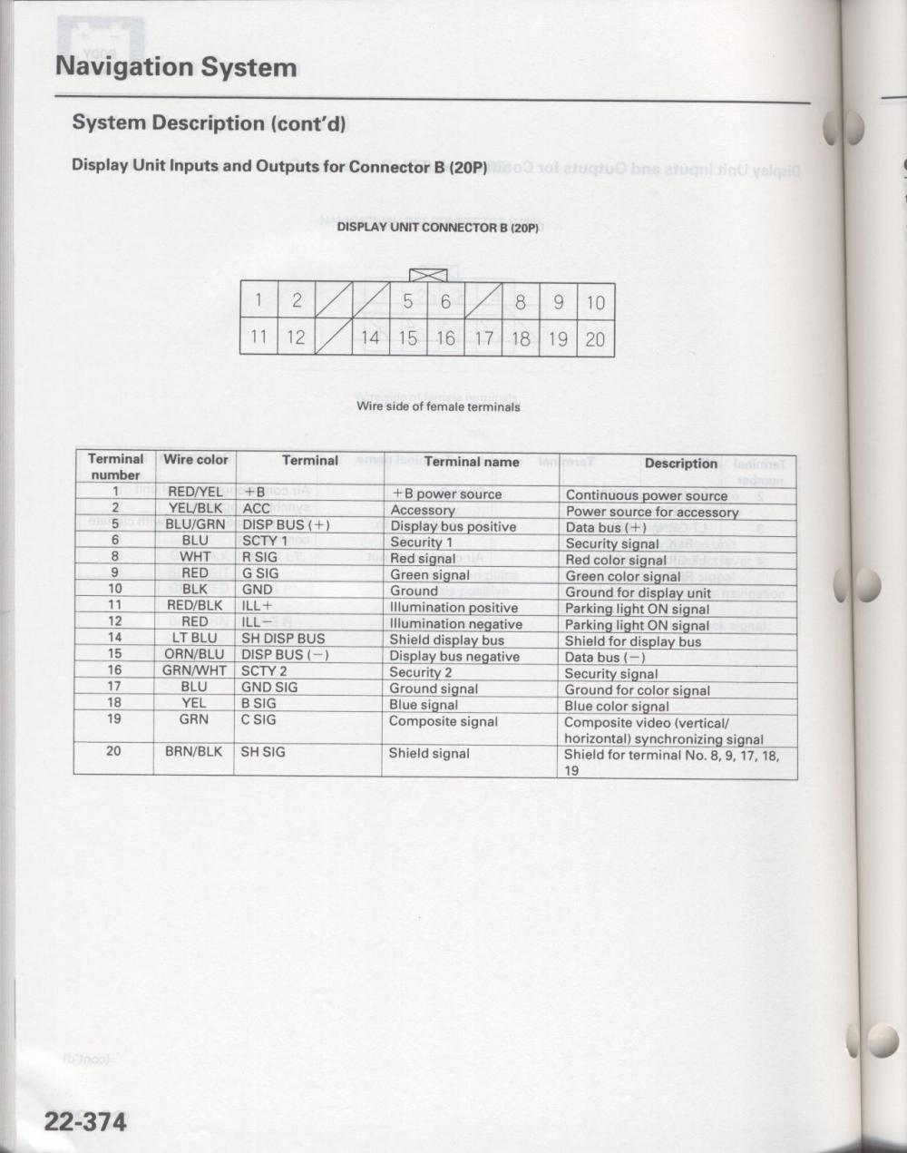
use this wiring diagram
and connect the wires as follows
it looks like you need to cut the color(red,green,blue) wires in half and use the end going to the tv as out and the wire coming from the trunk as in, same goes with the sync wire
DB9 - ----------------------screen harness (20P)
1(ground)----------------- 10(ground) black wire
2Sync ----------------------19(sync) green wire
3Red out------------------- 8(red) white wire
4Red in ---------------------8(red) white wire
5Green in------------------ 9Green) red wire
6Green out -----------------9(green) red wire
7Blue out -------------------18(blue) yellow wire
8Blue in ---------------------18(blue) yellow wire
9Sync out -------------------19(sync) green wire
if you do it from the trunk the same rules apply just a different pin out
DB9 -------------------------- dvd drive harness (12P)
1(ground)----------------- 12(ground) blue wire
2Sync ----------------------11(sync) green wire
3Red out------------------- 4(red) white wire
3Red in--------------------- 4(red) white wire
5Green in------------------ 5(green) red wire
6Green out -----------------5(green) red wire
7Blue out -------------------10(blue) yellow wire
8Blue in ---------------------10(blue) yellow wire
9Sync out -------------------11(sync) green wire
08-06-2004, 04:01 PM
#27
Racer

Join Date: Oct 2001
Location: Brooklyn, NY
Age: 54
Posts: 310
Likes: 0
Received 0 Likes
on
0 Posts
ok please follow what below only
Behind navi unit in the trunk should be 12pin plug, wires are next to each other.
1.cut WHITE wire coming from navi unit, wires from module connect red toward screen and yellow towards navi unit
2. cut RED wire coming from navi unit, wires from module connect blue toward screen and green towards navi unit
3. cut YELLOW wire coming from navi unit, wires from module connect violet toward screen and orange towards navi unit
4. cut GREEN wire coming from navi unit, wires from module connect black toward screen and brown towards navi unit
5. take BLUE coming from navi unit, wires from module connect black with letters into blue of navi screen
red connect to switch that is connected to 12V
red wit black stripes connect to parking brake.
Please solder all connections.
DO NOT WATCH WHILE DRIVING, CHECK LOCAL LAWS.
INTENDED ONLY FOR OFF ROAD USE
WE ARE NOT RESPONSIBLE FOR ANY DAMAGE TO YOUR NAVIGATION FROM IMPROPER INSTALLATION.
08-06-2004, 05:56 PM
#28
Burning Brakes
Thread Starter
Join Date: Jul 2003
Location: Long Island, NY
Age: 43
Posts: 1,081
Likes: 0
Received 0 Likes
on
0 Posts
So instead of the red with black to parking brake it can just be connected to a ground (ie cig lighter) to complete and allow for bypass of parking brake right?
Oh and thanks for these instructions MUCH better
Oh and thanks for these instructions MUCH better
08-06-2004, 07:52 PM
#31
Registered User
Originally Posted by KissMy_Type_S
any idea about the red/black wire goin to a ground rather than the p-brake, before the site shuts down and I'll never know 
use a test light an find out
it's either gonna be +12V or ground
08-09-2004, 06:33 AM
#33
Burning Brakes
Thread Starter
Join Date: Jul 2003
Location: Long Island, NY
Age: 43
Posts: 1,081
Likes: 0
Received 0 Likes
on
0 Posts
Well the install went very well... Simple to do with the second set of instructions. I didnt take pictures of every step because it was really tight quarters plus my soldering was a mess but I will post pics of how it looks finished plus I can go back and take pictures if anyone needs a reference for something.
If anyone is in the LI/NY area that needs help send me a PM
Thanks again to Jonsei, and rbf, and of course vsokolov. Ive been watching seasons 1 & 2 of Family Guy all weekend
If anyone is in the LI/NY area that needs help send me a PM
Thanks again to Jonsei, and rbf, and of course vsokolov. Ive been watching seasons 1 & 2 of Family Guy all weekend
08-09-2004, 09:33 AM
#34
Senior Moderator
I have a question.. When I looked there was two yellow wires behind the Navi Dvd unit. I looked quick but that's what I saw. And per the Vsolokov directions do you cut and make the wires a Y connection with the before and after? I'm also confused on step #5..
Kiss - Where did you run the switch and was it long enough? Did you connect in the trunk?
Kiss - Where did you run the switch and was it long enough? Did you connect in the trunk?
08-09-2004, 10:13 AM
#35
Burning Brakes
Thread Starter
Join Date: Jul 2003
Location: Long Island, NY
Age: 43
Posts: 1,081
Likes: 0
Received 0 Likes
on
0 Posts
Theres a yellow and a yellow/white wire, you dont touch that one. The yellow/white one is commin from somewhere else.
You actually cut the wire and solder one colored wire towards the harness and another colored wire towards the wire going back into the car.
I installed in the trunk just cuz it was the safer bet but i did cut and splice additional wire to both the 12V and the switch.
I'll take pictures of how and where I ran the wires and how and where i ran the switch if you'd like.
I mounted the switch inside the front armrest next to the cig. plug, which was also a good place to run the 12V for the AV box.
08-09-2004, 10:37 AM
#38
Senior Moderator
Originally Posted by KissMy_Type_S
just strip away some of the insulation on the Blue wire and solder the black w/ letters wire to it.
08-09-2004, 12:42 PM
#39
Burning Brakes
Thread Starter
Join Date: Jul 2003
Location: Long Island, NY
Age: 43
Posts: 1,081
Likes: 0
Received 0 Likes
on
0 Posts
Not a prob... If your up for takin a little drive, swing by the BBQ meet @ Ross Dock Park (Its in "Meet & Greet") on the 18th, i can give you a hand at the meet if theres still things ure unsure about.
09-05-2004, 11:35 PM
#40
Racer
Join Date: May 2003
Location: PA
Posts: 270
Likes: 0
Received 0 Likes
on
0 Posts
Originally Posted by KissMy_Type_S
Well the install went very well... Simple to do with the second set of instructions. I didnt take pictures of every step because it was really tight quarters plus my soldering was a mess but I will post pics of how it looks finished plus I can go back and take pictures if anyone needs a reference for something.
If anyone is in the LI/NY area that needs help send me a PM
Thanks again to Jonsei, and rbf, and of course vsokolov. Ive been watching seasons 1 & 2 of Family Guy all weekend
If anyone is in the LI/NY area that needs help send me a PM
Thanks again to Jonsei, and rbf, and of course vsokolov. Ive been watching seasons 1 & 2 of Family Guy all weekend
Hey,
I just did my install and I am getting lines ( noise) on my screen.
Have you experienced that???

Thread
Thread Starter
Forum
Replies
Last Post
08_UA7_Gr33k
Member Cars for Sale
13
02-11-2016 02:17 PM
lanechanger
Member Cars for Sale
4
10-13-2015 10:56 AM
us285126
3G TL Audio, Bluetooth, Electronics & Navigation
9
10-02-2015 02:03 PM