
2nd Gen TL CT-Supercharger on A 3rd Gen TL
 07-16-2012, 12:29 AM
#1
2nd Gen TL CT-Supercharger on A 3rd Gen TL
Alright guys the question that many people have asked before will a CT Supercharger off a 2nd gen TL fit a 3rd gen TL? And if not what will it take to make it fit? Well after much headache and trial and error I believe I am the first person to make a that possible!
From the beginning......
You may ask and wonder WHY would I want to put myself through this headache when I can just purchase a kit that will already fit my car? Well let me explain I went and purchased a used kit for the 2nd Gen TL without doing alot of research "I know I know Stupid on my part" and believe me I got an ear full from the wifey! I tried to sell the kit so that I can use some of that money to purchase the right kit. Well to my surprise the kit wasent selling so now I am getting a little worried so after much thinking and plenty of calls to Magnusun and CT I decided to do whatever it takes to make this kit fit so that my$2200 investment dosent just sit in my garage.
Starting to get interesting.....
So I get in contact with my buddy from Fast Eddies Racing in which they are responsible for perfecting a reverse head on a H22 motor heres a pic to see what im talking about and are used to building many one off motors and projects all the time.
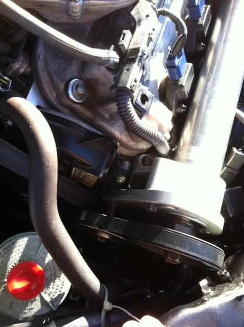
So at this point all we had to do was measeure the drive shaft and shorten it to line up the pulley with all the belts on the motor and order the right pulley from CT so that we can drive the Charger with the motor. What we decided to do and to be different is that we wanted to do the exact setup on the 2nd gen TL and run the 2 pulley setup and run the Charger off the alternator pulley VS a single belt setup like on the 3rd Gen setup. So that if the belt on the Charger were ever to break we can still drive the car home and not be fully out of commission. What we also decided to do was to go ahead and just modify both elbows instead of buying new ones designed for the 3rd gen TL from CT cause they charge a arm and a leg for it! So at this point I am like It looks like this can happen.
Point of no return......
So after 2 weeks the drive shaft was shortened and balanced and new bearings were installed along with both elbows 1 for the intake manifold and 1 elbow for the throttle body were both filled and drilled so that it will line up perfect when we bolt everthing together. During that time I started ordering parts that I would need to make this kit reliable and working.
AEM FIC
AEM Wiring Harness
AEM AFR Guage
AEM Boost Guage
Spacer From CT for intake manifold
FPR Crushing Tool
Braille 17lb Battery
NGK 1 Step Colder Iridium Plugs X6
Silicon Hoses for Radiator
Now the headache begins.......
Now its D-Day meaning Install Day. Thinking that we covered everything that we would need we thought wrong! 1st The drive shaft was perfect but the Bracket that mounts on to the alternator didnt line up were we wanted it too so we had to fabricate the right bracket out of the exsisting baracket and drill and tap the holes so that we can bolt the charger to it seems easy but that took 7 hrs just for that. 2nd of course the battery tray didnt fi so I chopped that baby up and mounted it were its supposed to be that took 2hrs alone just for fabricating that. 3rd the tensioner pulley that came with the 2nd Gen Kit is too wide and if we were going to use that it would hit the valve cover so we ended up using a tensioner pulley for the AC of a Civic motor. 4th the spacing of the pulley on the Charger wasent lining up with the tensioner so we had to fabricate new shims for the pulley so that will line up properly. So now were are on day 2 of the install and working on the 22nd hour of installing and fabrication to make this kit fit.
Finally She's ALIVE........
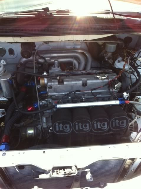
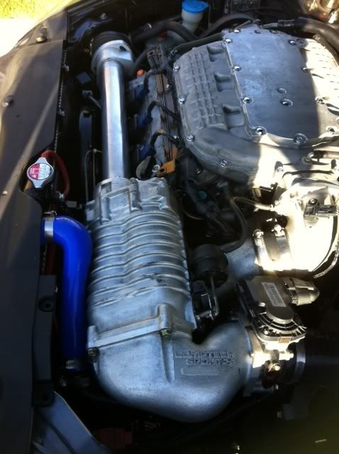
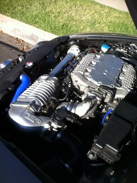
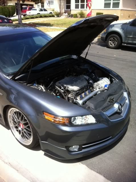
Now its 8am on day 3 of install and we get everything installed! and everthing is running great. So the question is Can it be done and the answer is YES! Will I recommend doing this I would say its up to you! LOL The cost on doing something like this Ill just say for all the stuff I bought Charger and all the extras its still comes out to about $3100 so cheaper than a new kit and still cheaper than used ones on the BM and mine has evrything you need Guages,FIC, and Battery. I know for a fact I'm forgetting alot of other details I will add more as I remember them. Now on to the pics
Install
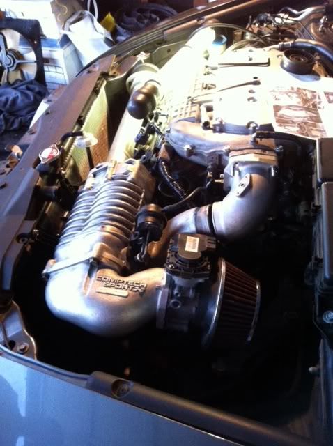
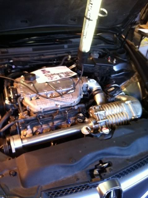
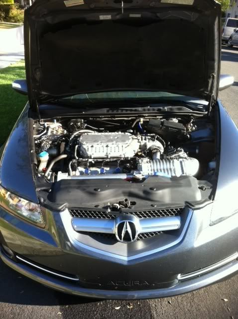
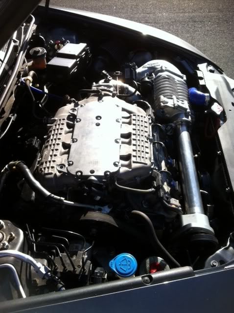
Finished
Double Pulley Setup (I had to hammer the support a little for more room)
Other View
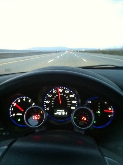
Guages
Sorry for the velcro guage pods coming in soon
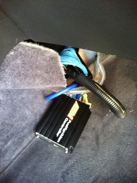
AEM FIC I know needs to be hidden
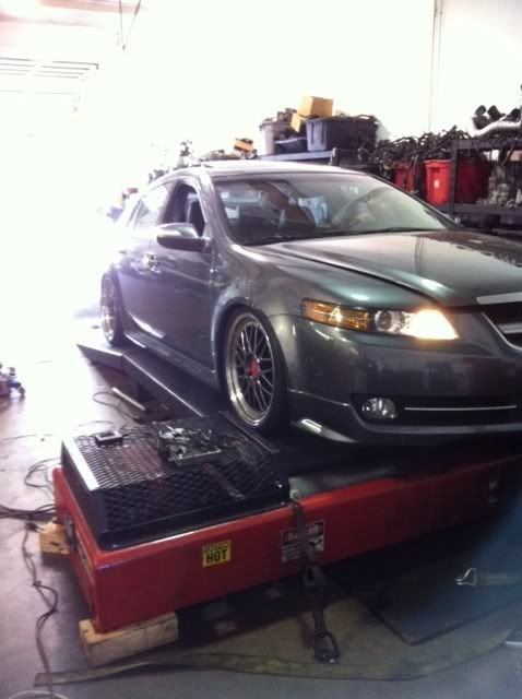
So Im on the DYNO as were tuning we are noticing that at high RPM'S we were losing boost and could not figure out why it was doing that I couldnt stay and figure it out plus I was leaving for vegas so we finished off at 263LBS of Torque and 253HP
Pics at the Dyno
So i am back now from Vegas and I figured out WHY I was losing boost all I needed to do was tighten the tensioner more on the Charger pulley more and BAM steady 4-5LBS of boost. And as of 7/15/12 I have a Dyno appt setup for tomorrow 7/16/12. Heres a vid of the motor running sorry for the crappy quality in the pics and the video!
And a video from the Dyno
Thanks for looking I just want to thank the following people for making this build possible
Tommy and Eddie from Fast Eddies
http://www.facebook.com/FastEddiesRacing
Cheiu From 4AE Auto for wiring the FIC
David from Import Auto Pros for help on the Dyno
Ferdie from South Coast Subaru for all the help on the parts
Nate and Chris From CT-Engineering for all your tech help.
And to AZINE for introducing me to the MONEY PIT LOL
LOL
From the beginning......
You may ask and wonder WHY would I want to put myself through this headache when I can just purchase a kit that will already fit my car? Well let me explain I went and purchased a used kit for the 2nd Gen TL without doing alot of research "I know I know Stupid on my part" and believe me I got an ear full from the wifey! I tried to sell the kit so that I can use some of that money to purchase the right kit. Well to my surprise the kit wasent selling so now I am getting a little worried so after much thinking and plenty of calls to Magnusun and CT I decided to do whatever it takes to make this kit fit so that my$2200 investment dosent just sit in my garage.
Starting to get interesting.....
So I get in contact with my buddy from Fast Eddies Racing in which they are responsible for perfecting a reverse head on a H22 motor heres a pic to see what im talking about and are used to building many one off motors and projects all the time.
So at this point all we had to do was measeure the drive shaft and shorten it to line up the pulley with all the belts on the motor and order the right pulley from CT so that we can drive the Charger with the motor. What we decided to do and to be different is that we wanted to do the exact setup on the 2nd gen TL and run the 2 pulley setup and run the Charger off the alternator pulley VS a single belt setup like on the 3rd Gen setup. So that if the belt on the Charger were ever to break we can still drive the car home and not be fully out of commission. What we also decided to do was to go ahead and just modify both elbows instead of buying new ones designed for the 3rd gen TL from CT cause they charge a arm and a leg for it! So at this point I am like
It looks like this can happen.Point of no return......
So after 2 weeks the drive shaft was shortened and balanced and new bearings were installed along with both elbows 1 for the intake manifold and 1 elbow for the throttle body were both filled and drilled so that it will line up perfect when we bolt everthing together. During that time I started ordering parts that I would need to make this kit reliable and working.
AEM FIC
AEM Wiring Harness
AEM AFR Guage
AEM Boost Guage
Spacer From CT for intake manifold
FPR Crushing Tool
Braille 17lb Battery
NGK 1 Step Colder Iridium Plugs X6
Silicon Hoses for Radiator
Now the headache begins.......
Now its D-Day meaning Install Day. Thinking that we covered everything that we would need we thought wrong! 1st The drive shaft was perfect but the Bracket that mounts on to the alternator didnt line up were we wanted it too so we had to fabricate the right bracket out of the exsisting baracket and drill and tap the holes so that we can bolt the charger to it seems easy but that took 7 hrs just for that. 2nd of course the battery tray didnt fi so I chopped that baby up and mounted it were its supposed to be that took 2hrs alone just for fabricating that. 3rd the tensioner pulley that came with the 2nd Gen Kit is too wide and if we were going to use that it would hit the valve cover so we ended up using a tensioner pulley for the AC of a Civic motor. 4th the spacing of the pulley on the Charger wasent lining up with the tensioner so we had to fabricate new shims for the pulley so that will line up properly. So now were are on day 2 of the install and working on the 22nd hour of installing and fabrication to make this kit fit.
Finally She's ALIVE........
Now its 8am on day 3 of install and we get everything installed! and everthing is running great. So the question is Can it be done and the answer is YES! Will I recommend doing this I would say its up to you! LOL The cost on doing something like this Ill just say for all the stuff I bought Charger and all the extras its still comes out to about $3100 so cheaper than a new kit and still cheaper than used ones on the BM and mine has evrything you need Guages,FIC, and Battery. I know for a fact I'm forgetting alot of other details I will add more as I remember them. Now on to the pics
Install
Finished
Double Pulley Setup (I had to hammer the support a little for more room)
Other View
Guages
Sorry for the velcro guage pods coming in soon
AEM FIC I know needs to be hidden
So Im on the DYNO as were tuning we are noticing that at high RPM'S we were losing boost and could not figure out why it was doing that I couldnt stay and figure it out plus I was leaving for vegas
so we finished off at 263LBS of Torque and 253HPPics at the Dyno
So i am back now from Vegas and I figured out WHY I was losing boost all I needed to do was tighten the tensioner more on the Charger pulley more and BAM steady 4-5LBS of boost. And as of 7/15/12 I have a Dyno appt setup for tomorrow 7/16/12. Heres a vid of the motor running sorry for the crappy quality in the pics and the video!
And a video from the Dyno
Thanks for looking I just want to thank the following people for making this build possible
Tommy and Eddie from Fast Eddies
http://www.facebook.com/FastEddiesRacing
Cheiu From 4AE Auto for wiring the FIC
David from Import Auto Pros for help on the Dyno
Ferdie from South Coast Subaru for all the help on the parts
Nate and Chris From CT-Engineering for all your tech help.
And to AZINE for introducing me to the MONEY PIT
LOL
Last edited by ziggyh22; 07-16-2012 at 12:36 AM. Reason: Added pic
 07-16-2012, 10:55 AM
#3
Nice work ziggy I did the Velcro mounted guages too, didn't like the way the pods looked. Also have my fic resting on the floor for now
That's good that you were able to get 4-5 lbs of boost, I cant seem to get more than 3.9lbs. What was the ambient temperature when you did your dyno pulls?
I did the Velcro mounted guages too, didn't like the way the pods looked. Also have my fic resting on the floor for nowThat's good that you were able to get 4-5 lbs of boost, I cant seem to get more than 3.9lbs. What was the ambient temperature when you did your dyno pulls?
07-16-2012, 05:11 PM
#4
Thanks I have a new Dyno sheet its ok I guess still have some issues.
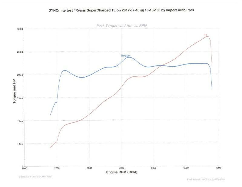
Thanks yeah Ill see how the new pods look and ill decide from there if ill keep it or not. So I went in for the dyno today and I have some questions for you! When we pull on the dyno once we hit 4-5 lbs of boost we get a check engine light and the code reads Barometric pressure high so were thinking the MAP is reading the boost pressure and causing that code. Do you get that code since your on FIC and if so what did you do to fool the system not to read boost? We are thinking of adding a part called "missing link" which is a one way bypass to help vacuum flow through but not let boost enter the MAP area. The other thing we noticed is as the temperature in the motor increases we start loosing boost goes to 3-2 we let the car sit and cool down then we see 3-4-5 do you run into that problem? Seems like to us that as the motor gets hotter the belt starts to slip. I adjusted tension and it helped pick up the boost again but the belt is pretty tight already. TLoveit your input would be greatly appreciated! Heres the dyno graph not bad considering i only have a j-pipe no 3rd cat and no mid muffler pretty much stock. So final numbers are 283 hp and 246lbs of torque.
I know once we figure out the check engine light problem we can squeeze more out of it
Nice work ziggy I did the Velcro mounted guages too, didn't like the way the pods looked. Also have my fic resting on the floor for now
That's good that you were able to get 4-5 lbs of boost, I cant seem to get more than 3.9lbs. What was the ambient temperature when you did your dyno pulls?
I did the Velcro mounted guages too, didn't like the way the pods looked. Also have my fic resting on the floor for nowThat's good that you were able to get 4-5 lbs of boost, I cant seem to get more than 3.9lbs. What was the ambient temperature when you did your dyno pulls?
Heres the dyno graph not bad considering i only have a j-pipe no 3rd cat and no mid muffler pretty much stock. So final numbers are 283 hp and 246lbs of torque.I know once we figure out the check engine light problem we can squeeze more out of it
Last edited by ziggyh22; 07-16-2012 at 05:14 PM. Reason: added text
The following users liked this post:
ziggyh22 (07-17-2012)
07-16-2012, 09:31 PM
#6
Thanks yeah Ill see how the new pods look and ill decide from there if ill keep it or not. So I went in for the dyno today and I have some questions for you! When we pull on the dyno once we hit 4-5 lbs of boost we get a check engine light and the code reads Barometric pressure high so were thinking the MAP is reading the boost pressure and causing that code. Do you get that code since your on FIC and if so what did you do to fool the system not to read boost? We are thinking of adding a part called "missing link" which is a one way bypass to help vacuum flow through but not let boost enter the MAP area. The other thing we noticed is as the temperature in the motor increases we start loosing boost goes to 3-2 we let the car sit and cool down then we see 3-4-5 do you run into that problem? Seems like to us that as the motor gets hotter the belt starts to slip. I adjusted tension and it helped pick up the boost again but the belt is pretty tight already. TLoveit your input would be greatly appreciated!
Heres the dyno graph not bad considering i only have a j-pipe no 3rd cat and no mid muffler pretty much stock. So final numbers are 283 hp and 246lbs of torque. As far as loosing boost; I don't think the heat would cause your belt to slip as tension is usually less when belt is cold. Be careful not to over tighten the belt causing excessive drag. The heat may be affecting you SC and that is very bad. If you haven't yet, look in to Water/Meth cooling.
 Your numbers look good for the setup you have. I hope one of the more experienced guys will chime in. There are quite a few people with tons of knowledge. Sorry I couldn't help more but I will keep you posted if I hear anyhting that may help.
Good luck and keep us posted.
The following users liked this post:
ziggyh22 (07-17-2012)
The following users liked this post:
ziggyh22 (07-17-2012)
Trending Topics
07-17-2012, 03:00 AM
#8
Man, I wish I could be of more help but I'm still new to this game and have alot to learn. I didn't run into the "Barometric pressure high code" and have never actually read or heard about it until now As far as loosing boost; I don't think the heat would cause your belt to slip as tension is usually less when belt is cold. Be careful not to over tighten the belt causing excessive drag. The heat may be affecting you SC and that is very bad. If you haven't yet, look in to Water/Meth cooling.
Your numbers look good for the setup you have. I hope one of the more experienced guys will chime in. There are quite a few people with tons of knowledge. Sorry I couldn't help more but I will keep you posted if I hear anyhting that may help.
Good luck and keep us posted.
As far as loosing boost; I don't think the heat would cause your belt to slip as tension is usually less when belt is cold. Be careful not to over tighten the belt causing excessive drag. The heat may be affecting you SC and that is very bad. If you haven't yet, look in to Water/Meth cooling. Your numbers look good for the setup you have. I hope one of the more experienced guys will chime in. There are quite a few people with tons of knowledge. Sorry I couldn't help more but I will keep you posted if I hear anyhting that may help.
Good luck and keep us posted.
The following users liked this post:
ziggyh22 (07-17-2012)


The following users liked this post:
Acura TL Builder (01-04-2018)
07-17-2012, 05:02 PM
#14
Hahahah thats what I was thinking! Hahahah
@HISPEED I was wondering what will happen if I put the MAP sensor back on the original throttle body location? So that the sensor wont see boost anymore? Please chime in. Thanks
 07-17-2012, 10:05 PM
#17
Thanks rptls08 i will definitely hit you up when I'm ready to pull the trigger
Hahahah thats what I was thinking! Hahahah
@HISPEED I was wondering what will happen if I put the MAP sensor back on the original throttle body location? So that the sensor wont see boost anymore? Please chime in. Thanks
Hahahah thats what I was thinking! Hahahah
@HISPEED I was wondering what will happen if I put the MAP sensor back on the original throttle body location? So that the sensor wont see boost anymore? Please chime in. Thanks
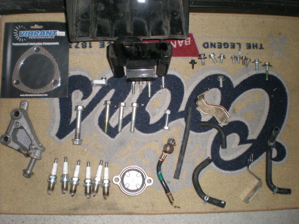
I have not run the sc for so long I don't remember where the map sensor was moved to. I do remember the little block off plate and it shouldn't cost more than $50 at the most. I will look for the pics here in a moment to see if I can find one of the kit all layed out for you.
 07-18-2012, 11:13 AM
#19
Burning Brakes
This looks like a lot of work. But props to you on doing this. Nice Job.
07-18-2012, 11:13 AM
#20
Yeah thats next on the list. I wanted to do it step by step and very time I added something I wanted to hit the Dyno to see what kind of gains I get. I know it'll get expensive I guess I just want to make my own personal log.
Yeah thats very true! Which setup did you go with? oops never mind I just checked your sig and your using RV6 thats the same stuff i'm looking into now
@SLIM Thank you sir!
Oh ok I see it yeah I made my own block off plate. I believe that goes on the original location on the throttle body in which I already have it blocked off. I got off the phone with CT this morning and they said that they think my clamp voltage is set to high so I'm going to take it back and adjust down to atleast 2.9 volts and see what that does hoepfully that takes care of the issue But so far thanks for the input guys you've been great help
Yeah thats very true! Which setup did you go with? oops never mind I just checked your sig and your using RV6 thats the same stuff i'm looking into now
Oh ok I see it yeah I made my own block off plate. I believe that goes on the original location on the throttle body in which I already have it blocked off. I got off the phone with CT this morning and they said that they think my clamp voltage is set to high so I'm going to take it back and adjust down to atleast 2.9 volts and see what that does hoepfully that takes care of the issue
But so far thanks for the input guys you've been great help
Last edited by ziggyh22; 07-18-2012 at 11:15 AM.
07-27-2012, 12:09 AM
#21
@ HiSPEED I just ordered a part called "Missing LInk" supposed to be a 1 way valve for the map sensor so it dosent see boost! Have you heard about that? Hopefully that will take care of my issues
Heres the link to the part
http://www.inlinefour.com/missinglink.html
Heres the link to the part
http://www.inlinefour.com/missinglink.html
Last edited by ziggyh22; 07-27-2012 at 12:10 AM. Reason: added text
07-27-2012, 12:17 AM
#22
@ HiSPEED I just ordered a part called "Missing LInk" supposed to be a 1 way valve for the map sensor so it dosent see boost! Have you heard about that? Hopefully that will take care of my issues
Heres the link to the part
http://www.inlinefour.com/missinglink.html
Heres the link to the part
http://www.inlinefour.com/missinglink.html
Looks like it will work, I just don't understand what part you were missing from the CT kit to make it work. I thought the map block off plate was what you needed.
07-27-2012, 12:58 AM
#23
Thanks for the reply@HISPEED! I have the MAP block off plate which goes on the original Throttle body that part has been taken care of but it's the check engine light thats driving me crazy and from what the check engine light code its due to the MAP sensor seeing boost so I ordered the missing link so that the MAP wont see it. Its like the old school days when you would use a check valve from a fish tank to fool the map sensor not to see boost. Are you running FIC? if so what voltage do you have your clamp voltage set at?
07-27-2012, 12:44 PM
#24
Thanks for the reply@HISPEED! I have the MAP block off plate which goes on the original Throttle body that part has been taken care of but it's the check engine light thats driving me crazy and from what the check engine light code its due to the MAP sensor seeing boost so I ordered the missing link so that the MAP wont see it. Its like the old school days when you would use a check valve from a fish tank to fool the map sensor not to see boost. Are you running FIC? if so what voltage do you have your clamp voltage set at?
That's what it is, you are using the Fic instead of the ACM ( black box ) the kit came with. I was using the Fic but switched over to the J&R ECU so I'm not sure what the voltage was set at. The only CEL I have is for too rich in both banks and that isn't going away.
The following users liked this post:
ziggyh22 (07-27-2012)
07-27-2012, 12:49 PM
#25

I can't find the screenshot anymore that had my settings in it... I want to say the MAP clamp was set at 3.92V but it'll vary depending on your elevation. If you have access to an OBD-II scanner, you can check it easily enough. Just use it to scan through the live data on the ECU with the key "ON", but the engine off. It should give you the volts of the atmospheric pressure. Input that value into the F/IC.
07-27-2012, 03:27 PM
#26
I can't find the screenshot anymore that had my settings in it... I want to say the MAP clamp was set at 3.92V but it'll vary depending on your elevation. If you have access to an OBD-II scanner, you can check it easily enough. Just use it to scan through the live data on the ECU with the key "ON", but the engine off. It should give you the volts of the atmospheric pressure. Input that value into the F/IC.
07-27-2012, 05:40 PM
#27
have you guys ever heard about the RDX turbo motor running a check valve on the MAP sensor and it comes factory like that? I guess Honda is using that valve to control the factory MAP sensor from seeing boost aswell! I'm looking into that now and maybe I might be able to integrate that as well!
One other thing to check would be the wiring harness and make sure that sensor is wired in properly. Your car is newer than mine so my wiring diagram won't do you any good unfortunately. If you have an ECU pinout, just look for the MAP wire. In my case, it was a green/red wire with ~3 volts with the ignition switch on, and ~1 volt at idle. Make sure that wire is tied in to your F/IC harness.
The following users liked this post:
ziggyh22 (07-27-2012)
07-27-2012, 06:50 PM
#28
I think I heard someone mention that before, but I never really gave it any though. You really shouldn't need it if you're clamping the MAP properly. I ran an F/IC for around 1-1.5 years and never had any issues with it. Well, not with the MAP clamp functionality anyway.
One other thing to check would be the wiring harness and make sure that sensor is wired in properly. Your car is newer than mine so my wiring diagram won't do you any good unfortunately. If you have an ECU pinout, just look for the MAP wire. In my case, it was a green/red wire with ~3 volts with the ignition switch on, and ~1 volt at idle. Make sure that wire is tied in to your F/IC harness.
One other thing to check would be the wiring harness and make sure that sensor is wired in properly. Your car is newer than mine so my wiring diagram won't do you any good unfortunately. If you have an ECU pinout, just look for the MAP wire. In my case, it was a green/red wire with ~3 volts with the ignition switch on, and ~1 volt at idle. Make sure that wire is tied in to your F/IC harness.
Thanks again for your input and I will check the wiring and hook up the OBD scanner this weekend!


Thread
Thread Starter
Forum
Replies
Last Post
emailnatec
5G TLX Tires, Wheels & Suspension
29
09-28-2018 04:27 PM
rp_guy
Member Cars for Sale
9
07-16-2017 07:33 AM
RSpyder
Car Parts for Sale
5
09-30-2015 12:46 AM