
Visualogic VMOD (Media On Demand)
 02-09-2009 | 03:09 PM
#41

Thread Starter
Instructor
Joined: Feb 2007
Posts: 125
Likes: 0
From: Houston, TX
Thanks for the corrections, I am updating my diagram now. A few (more) questions:
1. What do you mean by normally open and normally closed?
2. When you talk about wiring all wires to the socket are there extra wires that will be needed? I was under the impression that the flat flex connector would be soldered right to the oem screen and then you'd plug in the relay socket to it, although I can't tell without having them in hand whether the flat flex connectors have openings on the hidden side to be plugged into so maybe that's where I'm confused.
3. Which flat flex connector is connected to the oem screen in the initial step? From your diagram it looks like both of them. Are both wired/soldered to the board or is just one of them wired/soldered and then the other plugs into it? Again it's difficult to understand without being able to see all of the sides of the flat flex connector.
Sorry for asking so many questions, I hope you're not getting too frustrated trying to explain this to me.
02-09-2009 | 03:48 PM
#43
2. When you talk about wiring all wires to the socket are there extra wires that will be needed? I was under the impression that the flat flex connector would be soldered right to the oem screen and then you'd plug in the relay socket to it, although I can't tell without having them in hand whether the flat flex connectors have openings on the hidden side to be plugged into so maybe that's where I'm confused.
Sorry for the confusion, but nothing gets solder to any of the factory parts. All your soldering will be done to the parts you purchased from digikey.
3. Which flat flex connector is connected to the oem screen in the initial step? From your diagram it looks like both of them. Are both wired/soldered to the board or is just one of them wired/soldered and then the other plugs into it? Again it's difficult to understand without being able to see all of the sides of the flat flex connector.
Dont worry you'll understand everything more as you keep reading and seeing pictures, i only understand complex circuitry like this cause i work with it on a dailly basis for my job.
02-09-2009 | 03:51 PM
#44
02-09-2009 | 04:17 PM
#45
Thread Starter
Instructor
Joined: Feb 2007
Posts: 125
Likes: 0
From: Houston, TX
Ah, now it's starting to become clearer. First I forgot that there are 2 ribbon cables and then I kinda thought that the 2 sets of flat connectors might be in case one didn't fit but I wasn't sure. I think I ended up ordering 4 of each of those just in case I screwed it up anyway so I'll probably end up with lots of extras LOL.
Thanks for explaining how the electrical circuits run, that makes sense now. I think I'll fully understand it once I actually have the pieces in my hand and see how they operate and fit together.
Okay so nothing gets soldered to the oem touchscreen, that's good! However, if nothing is soldered how is the whole DigiKey piece connected to the board? You mentioned that the ribbon is connected to the flat connecter on the oem touchscreen, so is there a flat connecter already on the touchscreen? Or is the flat connector from step 1 somehow connected to the touchscreen and that's what the ribbon is going to?
I'll post an updated diagram of what I'm picturing in my head soon.
02-09-2009 | 04:50 PM
#46
Ah, now it's starting to become clearer. First I forgot that there are 2 ribbon cables and then I kinda thought that the 2 sets of flat connectors might be in case one didn't fit but I wasn't sure. I think I ended up ordering 4 of each of those just in case I screwed it up anyway so I'll probably end up with lots of extras LOL.
Thanks for explaining how the electrical circuits run, that makes sense now. I think I'll fully understand it once I actually have the pieces in my hand and see how they operate and fit together.
1. Okay so nothing gets soldered to the oem touchscreen, that's good! However, if nothing is soldered how is the whole DigiKey piece connected to the board?
2.You mentioned that the ribbon is connected to the flat connecter on the oem touchscreen, so is there a flat connecter already on the touchscreen?
3 Or is the flat connector from step 1 somehow connected to the touchscreen and that's what the ribbon is going to?
I'll post an updated diagram of what I'm picturing in my head soon.

You will unplug the 4 pin ribbon and connect it to the flat connector. The flat connector has 4 prongs, that is where that jumper ribbon from digikey will be soldered to. You dont necessary have to solder it, you can place the bare wire from the ribbon in the eyelet and sandwich it with the relay. It will work that way but if the connection gets loose than you need to rip apart the dash to repair. But it will work.
I had to read this mp3 car thread like 10 times to make it all to sense in my head. It is very useful. http://www.mp3car.com/vbulletin/show...tegration.html
02-09-2009 | 05:09 PM
#47
Thread Starter
Instructor
Joined: Feb 2007
Posts: 125
Likes: 0
From: Houston, TX
Oh now that makes total sense. I never thought that we'd be unplugging the oem ribbon. I'll take a look at that mp3 thread you linked to when I get home from work in a bit.
This is what I have for the updated diagram. It's probably still not right but hopefully a lot closer.

This is what I have for the updated diagram. It's probably still not right but hopefully a lot closer.
02-09-2009 | 05:30 PM
#48
Oh now that makes total sense. I never thought that we'd be unplugging the oem ribbon. I'll take a look at that mp3 thread you linked to when I get home from work in a bit.
This is what I have for the updated diagram. It's probably still not right but hopefully a lot closer.
This is what I have for the updated diagram. It's probably still not right but hopefully a lot closer.
02-09-2009 | 06:02 PM
#49
Thread Starter
Instructor
Joined: Feb 2007
Posts: 125
Likes: 0
From: Houston, TX
Thats exactly it. Remeber that you dont have to mount the usb controller right there but that just where met152 did it so you have alot of room to move that controller around with what every length wire you want to use. I have all the digikey parts at home so ill put them in order and you can see how to wire it up.
I am going to owe you big time once I have this working!
02-09-2009 | 06:08 PM
#50
dont worry wiring is hardest part unless you are going to design your own custom skin to run on your pc. If you want to get informed about what front end to use with your carpc i suggest that you look around on mp3car forum and see how to use the carpc and what ever accessories you want to know about.
02-09-2009 | 06:11 PM
#51
Thread Starter
Instructor
Joined: Feb 2007
Posts: 125
Likes: 0
From: Houston, TX
dont worry wiring is hardest part unless you are going to design your own custom skin to run on your pc. If you want to get informed about what front end to use with your carpc i suggest that you look around on mp3car forum and see how to use the carpc and what ever accessories you want to know about.
02-09-2009 | 06:16 PM
#52
yeah down load all the skin editors and creators. That will help write the front end skin codes for ride runner (aka road runner). I am having a hard time writing the code for my engine management/monitoring system. I understand the wiring logic of all the components i just dont know how to make the sensors perform and the actuators to do things off of the carpc rather than placing switches every where.
02-09-2009 | 06:25 PM
#53
Thread Starter
Instructor
Joined: Feb 2007
Posts: 125
Likes: 0
From: Houston, TX
yeah down load all the skin editors and creators. That will help write the front end skin codes for ride runner (aka road runner). I am having a hard time writing the code for my engine management/monitoring system. I understand the wiring logic of all the components i just dont know how to make the sensors perform and the actuators to do things off of the carpc rather than placing switches every where.
02-09-2009 | 06:32 PM
#54
i havent load road runner yet since i dont have the touch screen situated but i did load windows xp pro on my carpc. But i do have road runner loaded on my laptop so i can play and get use to the interface and see what i want to change. But i think ill just use a premade one for now until i can understand how to create a skin.
02-09-2009 | 09:23 PM
#55
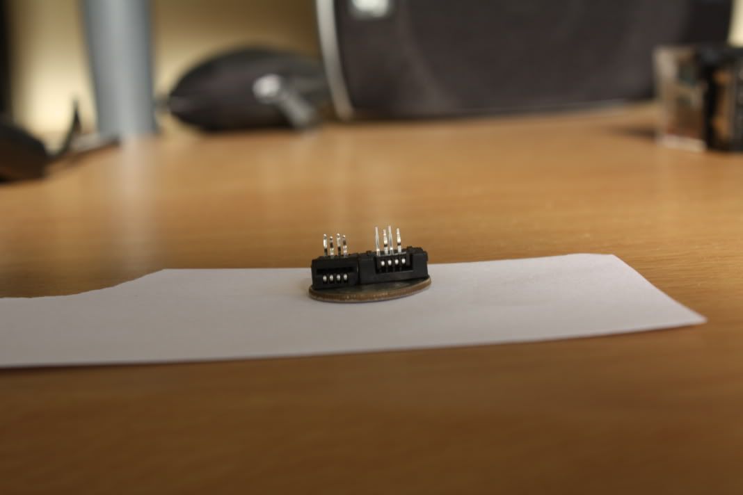
Ok this is how small the flat connectors are. I was able to fit one of each on a dime. Sorry about the horrible way of trying to show you how it will all come together. But this is the general idea of how it will all come together. So from the oem touchscreen it goes into a flat connector and from there the 4pin ribbon will get soldered on to the flat connector prongs and go to the common 4 legs of the relay. The 4 normally closed legs will will have the 4pin ribbon connected there and go back to the factory navi circuit board that the touchscreen 4 wires came from. The 4 normally open legs from the relay will go to the 4 wires of the usb control board. I do not know exactly to which colors yet but i will do research on the wiring schematics of both the 4 pins of the oem touchscreen and usb touchscreen controller. I didnt add wires for the 12v and ground going to the relay but that should be the least of your worries. I hope that will help you to understand now looking at the pieces that will be used to make this work.


02-09-2009 | 10:03 PM
#56
Thread Starter
Instructor
Joined: Feb 2007
Posts: 125
Likes: 0
From: Houston, TX
Hey those pics are great, I can't believe how tiny those connectors are!
It should be possible to put a lot of that together before putting it in the car right? At least a good bit of the soldering, or is that a bad idea? Do you plan on bringing your entire navi into your work space and installing it all there?
It should be possible to put a lot of that together before putting it in the car right? At least a good bit of the soldering, or is that a bad idea? Do you plan on bringing your entire navi into your work space and installing it all there?
02-09-2009 | 10:12 PM
#57
yes i will get it all soldered together and check the continuity each wire that way i know if any of them are touching each other before supplying it with power and i will bring in the whole navi to take apart the whole thing till i get to the navi circuit board.
02-09-2009 | 10:20 PM
#58
Thread Starter
Instructor
Joined: Feb 2007
Posts: 125
Likes: 0
From: Houston, TX
That's a good idea. When do you plan on doing the soldering and testing?
02-09-2009 | 10:29 PM
#59
I proably wont be pulling the navi unit until like 6 weeks from now since im going to be installing my air suspension and i need to run the air lines from the rear to the front and i figure i could rip the whole interior apart, but until than if you wanna help me write the skin for my engine management/monitoring that would be most appreciated. lol But feel free start the project without me and i will try to help any way i can.
02-09-2009 | 10:34 PM
#60
Thread Starter
Instructor
Joined: Feb 2007
Posts: 125
Likes: 0
From: Houston, TX
I proably wont be pulling the navi unit until like 6 weeks from now since im going to be installing my air suspension and i need to run the air lines from the rear to the front and i figure i could rip the whole interior apart, but until than if you wanna help me write the skin for my engine management/monitoring that would be most appreciated. lol But feel free start the project without me and i will try to help any way i can.
I'd be happy to help with the skin, I'll download Road Runner tomorrow and start looking into how to modify it.
02-16-2009 | 11:05 AM
#62
Thread Starter
Instructor
Joined: Feb 2007
Posts: 125
Likes: 0
From: Houston, TX
Alright well I got all of my parts in by Saturday but decided not to attempt putting this together since I'm not sure on where to solder each wire. Have you had any luck finding that out?
One thing I hadn't thought about is how do you plan on installing the relay assembly once it's together and in the car? I think that Met used a blank circuit board and then some type of black plastic housing, right?
Oh and those FFC's are TINY! I'm glad I ordered extra since I will probably break at least one.
02-16-2009 | 11:00 PM
#63
Alright well I got all of my parts in by Saturday but decided not to attempt putting this together since I'm not sure on where to solder each wire. Have you had any luck finding that out?
One thing I hadn't thought about is how do you plan on installing the relay assembly once it's together and in the car? I think that Met used a blank circuit board and then some type of black plastic housing, right?
Oh and those FFC's are TINY! I'm glad I ordered extra since I will probably break at least one.
One thing I hadn't thought about is how do you plan on installing the relay assembly once it's together and in the car? I think that Met used a blank circuit board and then some type of black plastic housing, right?
Oh and those FFC's are TINY! I'm glad I ordered extra since I will probably break at least one.
What part of soldering each wire are you not understanding correctly since there are many that need to be solder.
I was going to tape the relay to the back of the unit like how met did his once i had every circuit checked out and no bad soldering.
I did however get all my carpc pieces and was able to load windows xp pro and all the necessary drivers but that is as far as i can go now until i get the rest of my setup. Well good luck with your project.
02-16-2009 | 11:14 PM
#64
Thread Starter
Instructor
Joined: Feb 2007
Posts: 125
Likes: 0
From: Houston, TX
02-17-2009 | 12:38 AM
#65
sorry i wasnt trying to be a jerk i just wanted to have a little more clarification on which wires you were talking about since there are many that need to be solder. If you read the last part of that sentence i was asking for more clarification. 
02-17-2009 | 09:06 AM
#66
Thread Starter
Instructor
Joined: Feb 2007
Posts: 125
Likes: 0
From: Houston, TX

The reason that I asked that question about the wiring is because there are 14 of what I'd call "posts" on the bottom of the relay eye socket and I'm not sure which wire goes to which post. Or does that not matter?
Assuming that pin 1 from the ribbon goes to "post" 1, 2 to 2, 3 to 3, and 4 to 4:
Relay Eye Socket Posts
Row 1 - OEM Ribbon/FFC (Flat Flex Connector)
Row 2 - 4 pin Ribbon/FFC to USB controller
Row 3 - 4 pin Ribbon/FFC to Navi screen where OEM Ribbon typically connects.
Top Left - To Rocker Switch.
Top Right - Ground Wire
Does that sound right?
I'm also assuming that you would use wire to make the connections from the FFC to the RES posts. If that's true what gauge do you recommend using for the wire?
Since I haven't trimmed the 2 end pins from the ribbon yet I don't know if this is the case but will the ribbon "lock" into the FFC somehow?
I really think these are my final questions and I am truly thankful for all of the help that you have provided me and I plan on making a DIY for dummies (like me) once I'm finished with this project since I'm sure it can help a lot of other people. Like I said last week I definitely owe you!
02-17-2009 | 10:41 AM
#67
Sorry for being defensive there, it was a pretty long day and it was midnight here and the gf was nagging me to get to bed.
The reason that I asked that question about the wiring is because there are 14 of what I'd call "posts" on the bottom of the relay eye socket and I'm not sure which wire goes to which post. Or does that not matter?
The reason that I asked that question about the wiring is because there are 14 of what I'd call "posts" on the bottom of the relay eye socket and I'm not sure which wire goes to which post. Or does that not matter?
Assuming that pin 1 from the ribbon goes to "post" 1, 2 to 2, 3 to 3, and 4 to 4:
Relay Eye Socket Posts
Row 1 - OEM Ribbon/FFC (Flat Flex Connector)
Row 2 - 4 pin Ribbon/FFC to USB controller
Row 3 - 4 pin Ribbon/FFC to Navi screen where OEM Ribbon typically connects.
Top Left - To Rocker Switch.
Top Right - Ground Wire
Does that sound right?
Relay Eye Socket Posts
Row 1 - OEM Ribbon/FFC (Flat Flex Connector)
Row 2 - 4 pin Ribbon/FFC to USB controller
Row 3 - 4 pin Ribbon/FFC to Navi screen where OEM Ribbon typically connects.
Top Left - To Rocker Switch.
Top Right - Ground Wire
Does that sound right?
I'm also assuming that you would use wire to make the connections from the FFC to the RES posts. If that's true what gauge do you recommend using for the wire?
Since I haven't trimmed the 2 end pins from the ribbon yet I don't know if this is the case but will the ribbon "lock" into the FFC somehow?
I really think these are my final questions and I am truly thankful for all of the help that you have provided me and I plan on making a DIY for dummies (like me) once I'm finished with this project since I'm sure it can help a lot of other people. Like I said last week I definitely owe you!
02-17-2009 | 11:05 AM
#68
Thread Starter
Instructor
Joined: Feb 2007
Posts: 125
Likes: 0
From: Houston, TX
Yes that is correct but you need to make sure that you have them going to the right post. So your normally open circuit will be the will be the 4 wires from the usb controller. Your normally closed circuit will be the wires from the touchscreen and your common wires are the ones going back to the factory circuit board.

Yes once your trim off 1 wire on each side of the 6pin than you will be able to plug it into the FFC connector and solder off the other ends of that connector. A quick tip to expose the wires from the flex connectors would be to split all the wires enough to solder them, then take a lighter or a candle which i used and burn the plastic off, you will than need to clean the wires and you should be able to see the clean copper.
Let me know if you have anymore questions. One more final thing that i have not been able to figure out since there are no electrical circuitry on the touchscreen are the 4 wires. They correspond to x and y axis. The usb controller needs to be in sync with the x and y axis of the touch screen, if not then when you touch the screen the touch point will be indicated in a different location as it is being told by the usb controller.
02-17-2009 | 11:30 AM
#69
That makes sense! This is probably going to sound like a ridiculous question for you but how do you know which row are normally open, normally closed, and common? From this picture I know the front right is power and the front left is ground. I'll guess and say that from the back, row 1 is normally open, row 2 is normally closed, and row 3 is common. Is that right?
Oh that's good to know! I was just going to trim off 2 on one side so I'm glad that I didn't go ahead and do that yet. Thanks for the tip on the soldering as well!
Maybe when the drivers are installed by Windows for the USB controller there is a utility to calibrate that? If not then there has to be some type of software that can be used for that to adjust the coordinates in Windows. I will probably attempt to get this all installed this weekend and connect my laptop to the USB cable to see how the coordinates match up with Windows. It's probably too much to hope for that they are perfect without doing anything so if they aren't accurate then I'll try to find an app for calibrating it and I'll let you know what I used.
Maybe when the drivers are installed by Windows for the USB controller there is a utility to calibrate that? If not then there has to be some type of software that can be used for that to adjust the coordinates in Windows. I will probably attempt to get this all installed this weekend and connect my laptop to the USB cable to see how the coordinates match up with Windows. It's probably too much to hope for that they are perfect without doing anything so if they aren't accurate then I'll try to find an app for calibrating it and I'll let you know what I used.
02-17-2009 | 11:37 AM
#70
there is a calibration software and it is on the website that you bought the controller from.
http://shop-on-line.tvielectronics.c...ch-controllers
http://shop-on-line.tvielectronics.c...ch-controllers
02-17-2009 | 01:10 PM
#71
Thread Starter
Instructor
Joined: Feb 2007
Posts: 125
Likes: 0
From: Houston, TX
[quote=wrxyboy;10533361]There are two ways to find normally open, normally closed and common. First is to look on the relay and it will show the relay circuitry. The other way is to check continuity between normally closed and common.[quote]
I'll take a look at the relay when I get home tonight and see which ones are open, closed, and normal. I don't know how to check continuity so hopefully the relay circuitry is shown on there in a way that makes sense to me. This whole project is making me want to go learn about electrical engineering though I'll tell you that. I admire you guys for having the knowledge to do this type of work.
Too bad met didn't tell us which pin was which and he hasn't responded to a PM about this from me so I'm guessing he's not interested in talking about it anymore or he's not around.
It seems peculiar that they would need 2 pins for x and 2 for y. I noticed on the USB controller that the pin out is x,y,x,y so hopefully it's the same for the OEM wiring. Do you think the TL service manual would show that info? I bought one last year but haven't really used it.
Thanks for the link, I forgot about that calibration utility which I downloaded the day I bought the parts from that site.
I'll take a look at the relay when I get home tonight and see which ones are open, closed, and normal. I don't know how to check continuity so hopefully the relay circuitry is shown on there in a way that makes sense to me. This whole project is making me want to go learn about electrical engineering though I'll tell you that. I admire you guys for having the knowledge to do this type of work.
There is a windows utility to calibrate the controller, but i was going to only hook up two wire at a time and see where the show up on the calibration app. Hopefully it will tell me which two are y and which two are x without any problems. But that part will have to to be trial and error.
It seems peculiar that they would need 2 pins for x and 2 for y. I noticed on the USB controller that the pin out is x,y,x,y so hopefully it's the same for the OEM wiring. Do you think the TL service manual would show that info? I bought one last year but haven't really used it.
Thanks for the link, I forgot about that calibration utility which I downloaded the day I bought the parts from that site.
02-17-2009 | 02:44 PM
#72
[QUOTE=jaymurff25;10533757][quote=wrxyboy;10533361]There are two ways to find normally open, normally closed and common. First is to look on the relay and it will show the relay circuitry. The other way is to check continuity between normally closed and common.
To do a continuity check you will need a multimeter and all you are doing is checking to see if a circuit is complete. So you would go to leg 1 of common and normally closed and the multimeter will beep to let you know that there is continuous flow of current through the relay and the multimeter will let you know that is a complete circuit. This is also good to know when you solder everything together, you can check to see if leg 1 and 2 are touching by a small piece of solder it will tell you that the circuit is complete and you can fix it prior to installing everything.
Too bad met didn't tell us which pin was which and he hasn't responded to a PM about this from me so I'm guessing he's not interested in talking about it anymore or he's not around.
Yes the four wires are for x-,x+,y-,y+ which give coordinates to the computer of where you are touching. The tl manual does not show this complex computer circuitry since i think the techs would never have to trouble shoot that far and will replace the whole unit instead of spending labor time troubleshooting computer circuitry.
Thanks for the link, I forgot about that calibration utility which I downloaded the day I bought the parts from that site.
I'll take a look at the relay when I get home tonight and see which ones are open, closed, and normal. I don't know how to check continuity so hopefully the relay circuitry is shown on there in a way that makes sense to me. This whole project is making me want to go learn about electrical engineering though I'll tell you that. I admire you guys for having the knowledge to do this type of work.
Too bad met didn't tell us which pin was which and he hasn't responded to a PM about this from me so I'm guessing he's not interested in talking about it anymore or he's not around.
It seems peculiar that they would need 2 pins for x and 2 for y. I noticed on the USB controller that the pin out is x,y,x,y so hopefully it's the same for the OEM wiring. Do you think the TL service manual would show that info? I bought one last year but haven't really used it.
Thanks for the link, I forgot about that calibration utility which I downloaded the day I bought the parts from that site.
02-17-2009 | 02:56 PM
#73
if worst comes to worst with the touchscreen it maybe easier to replace the whole touchscreen its self.
http://shop-on-line.tvielectronics.c...-touch-screens
http://shop-on-line.tvielectronics.c...-touch-screens
02-17-2009 | 03:13 PM
#74
Thread Starter
Instructor
Joined: Feb 2007
Posts: 125
Likes: 0
From: Houston, TX
To do a continuity check you will need a multimeter and all you are doing is checking to see if a circuit is complete. So you would go to leg 1 of common and normally closed and the multimeter will beep to let you know that there is continuous flow of current through the relay and the multimeter will let you know that is a complete circuit. This is also good to know when you solder everything together, you can check to see if leg 1 and 2 are touching by a small piece of solder it will tell you that the circuit is complete and you can fix it prior to installing everything.
Yes the four wires are for x-,x+,y-,y+ which give coordinates to the computer of where you are touching. The tl manual does not show this complex computer circuitry since i think the techs would never have to trouble shoot that far and will replace the whole unit instead of spending labor time troubleshooting computer circuitry.
I figured that the TL manual probably wouldn't have it, but as big as that thing is it wouldn't surprise me if it did.
If worst comes to worst with the touchscreen it maybe easier to replace the whole touchscreen its self.
http://shop-on-line.tvielectronics.c...-touch-screens
http://shop-on-line.tvielectronics.c...-touch-screens
02-17-2009 | 03:42 PM
#75
That sounds pretty easy. I need to get myself a decent multimeter, I have a cheap one that I bought years ago that doesn't work all that well.
Perhaps it's a common thing but I wonder why the exact x,y coordinates can't be sent on 2 wires or even 1. If it's smart enough to know that it's on a positive or negative side of the axis that should just be the value of x (or y). It's not like you can be touching a positive and a negative position for x (or y) at the same time.
I figured that the TL manual probably wouldn't have it, but as big as that thing is it wouldn't surprise me if it did.
That's an interesting idea and really cheap too. Will an 8.4" fit? I thought I read that this screen is an 8" screen but maybe that was just a rounded off number.
Also for the 8.4 i am not sure how much of the navi screen is covered by the bezel and housing. The only way to know is to measure once you get that far into taking it apart.
02-17-2009 | 03:50 PM
#76
Thread Starter
Instructor
Joined: Feb 2007
Posts: 125
Likes: 0
From: Houston, TX
True with the coordinates but our navigation's system may not be that smart to understand the + & - axis of the touchscreen. Everything is determined from the navigation unit in the trunk and the navigation dvd so i dont know how in depth with detail that unit can go into.
Also for the 8.4 i am not sure how much of the navi screen is covered by the bezel and housing. The only way to know is to measure once you get that far into taking it apart.
Also for the 8.4 i am not sure how much of the navi screen is covered by the bezel and housing. The only way to know is to measure once you get that far into taking it apart.
Well let's hope that we won't need it. It really shouldn't be too difficult to determine through trial and error which are which.
02-17-2009 | 04:35 PM
#77
nah it shouldnt be. Just hook up the two outside wires and touch the screen and see where it registers on the calibration tool than do the other two and troubleshoot from there.
02-17-2009 | 06:02 PM
#78
just remembered this thread and i think i will try this route for turning on and off the carpc.
https://acurazine.com/forums/showthr...ght=switch+vsa
https://acurazine.com/forums/showthr...ght=switch+vsa
02-17-2009 | 06:16 PM
#79
Thread Starter
Instructor
Joined: Feb 2007
Posts: 125
Likes: 0
From: Houston, TX
just remembered this thread and i think i will try this route for turning on and off the carpc.
https://acurazine.com/forums/showthr...ght=switch+vsa
https://acurazine.com/forums/showthr...ght=switch+vsa
02-17-2009 | 06:34 PM
#80
yeah and the switch is only 7 dollars from www.acuraoemparts.com that way it looks factory still yet.