When you click on links to various merchants on this site and make a purchase, this can result in this site earning a commission. Affiliate programs and affiliations include, but are not limited to, the eBay Partner Network.
A safer way to eliminate hyperflashing after installing LED bulbs
You may have seen the method of opening up the flasher to replace the shunt with a resistor (thank you Roger555). That was a great idea, but I was concerned that all the bulbs would be drawing power through the resistor, and since people were replacing the shunt with a 1W resistor, that might not work for higher-powered LED setups like the V6 Triton Extreme bulbs, which draw 1.7A each, so if you have 4 of them, that's 6.8A through that 1W resistor! This could cause it to burn up (potential fire hazard), especially if anyone were ever to use regular incandescent bulbs again, so after some back and forth with peter6 (thank you peter6), I decided to try his idea of using a voltage divider to prevent the chip from activating hyperflash at any power level including zero.
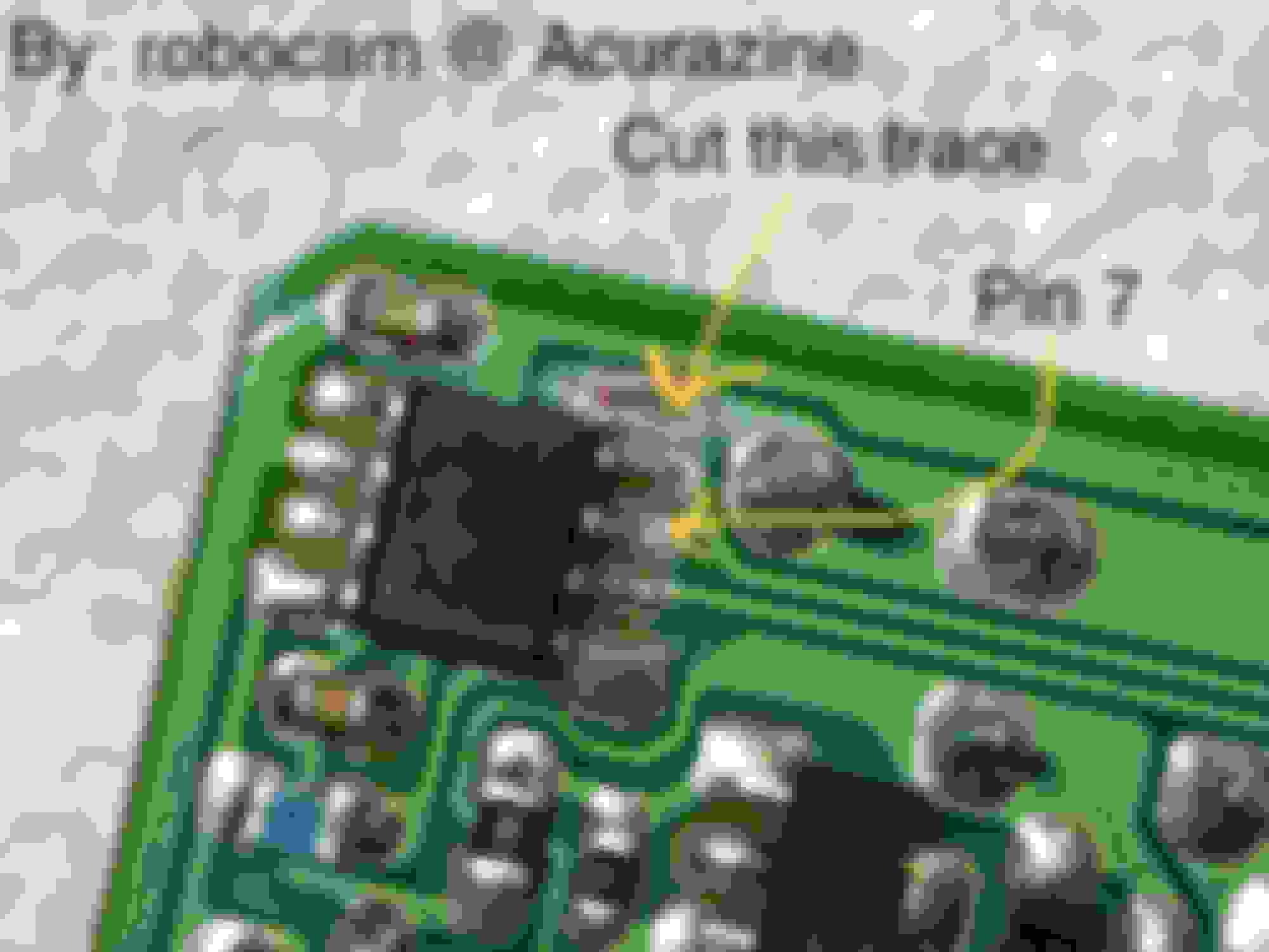
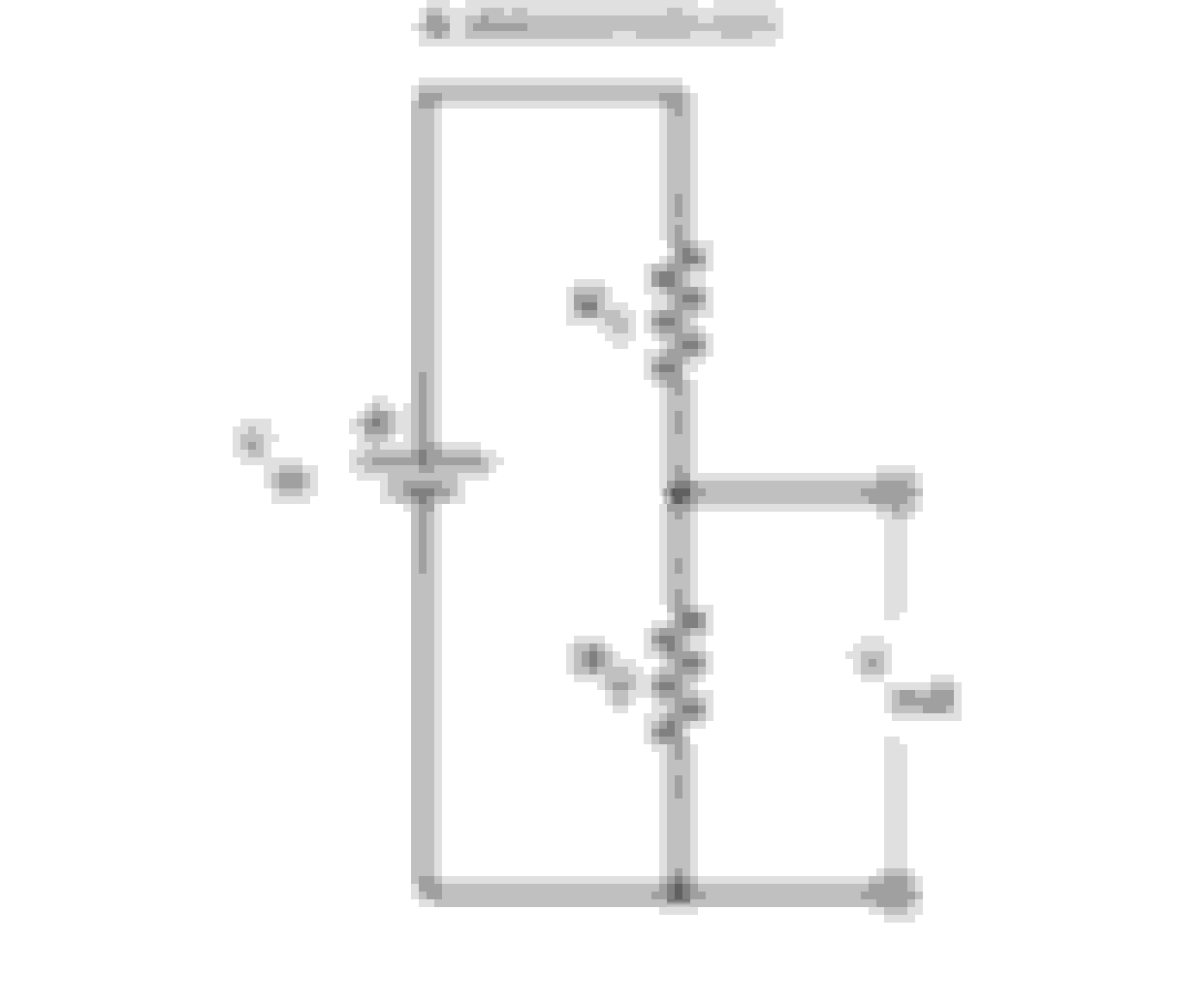
So how does this work? Basically, the flasher uses a shunt (an electrical conductor of known resistance [0.020 ohms in our case]) to measure the load from the bulbs. The chip reads the voltage across the shunt, and if it is lower than the predetermined level of 50 mV (such as when a bulb burns out), it will change the flashing rate to a higher frequency (aka hyperflash). This modification will disconnect the pin from the chip (pin 7) that measures the voltage across the shunt and send it a constant voltage (a voltage it would normally see in a case where all incandescent bulbs are operating normally) from a voltage divider. This way it will always flash at a normal rate despite the actual load.
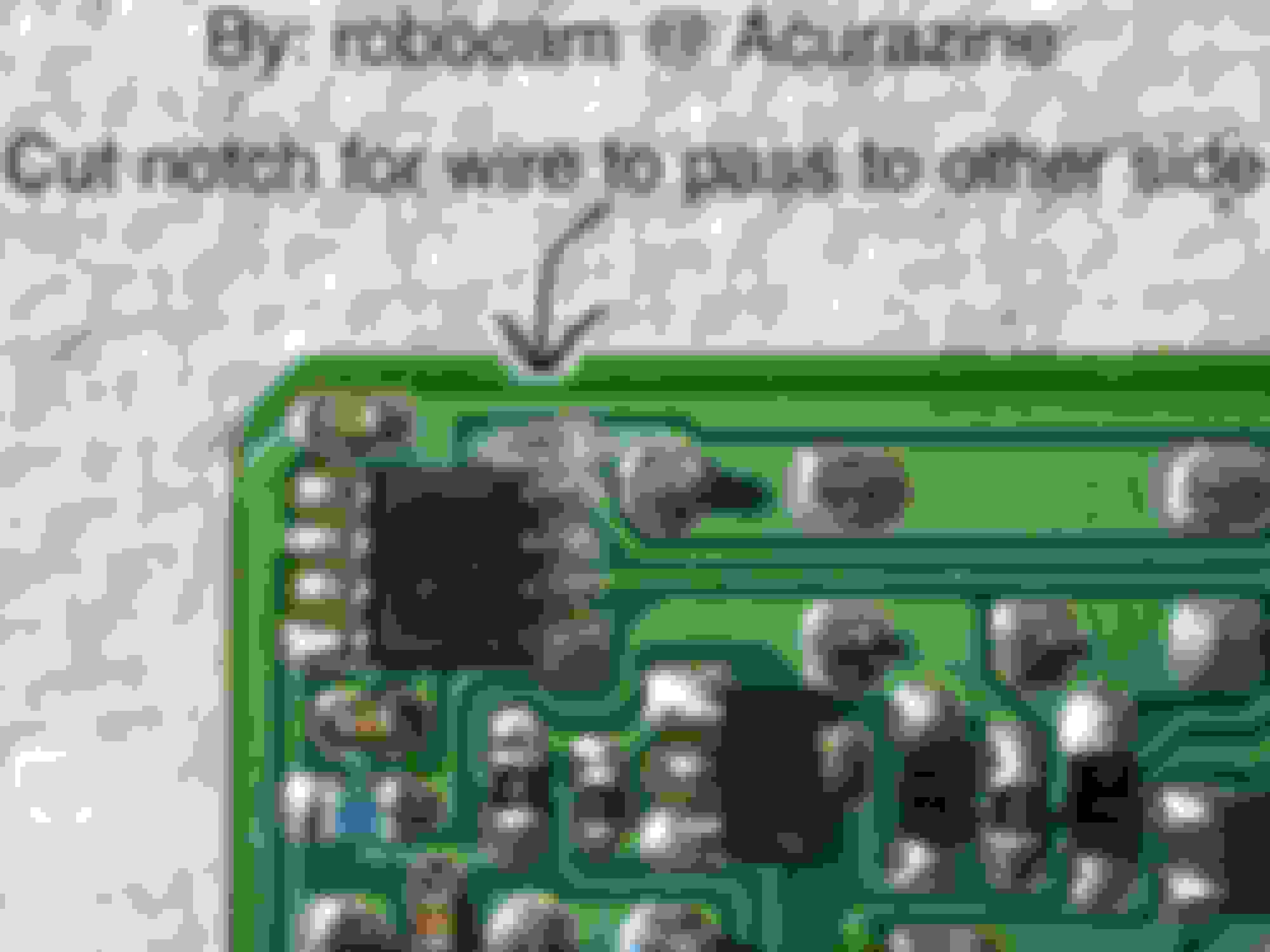
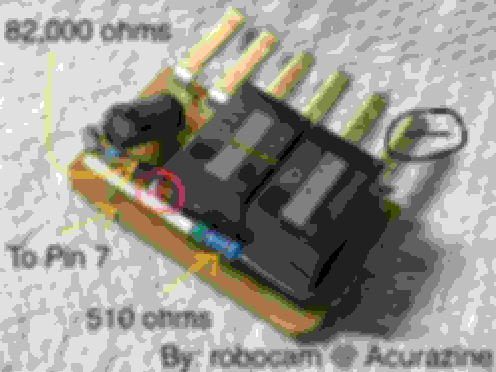
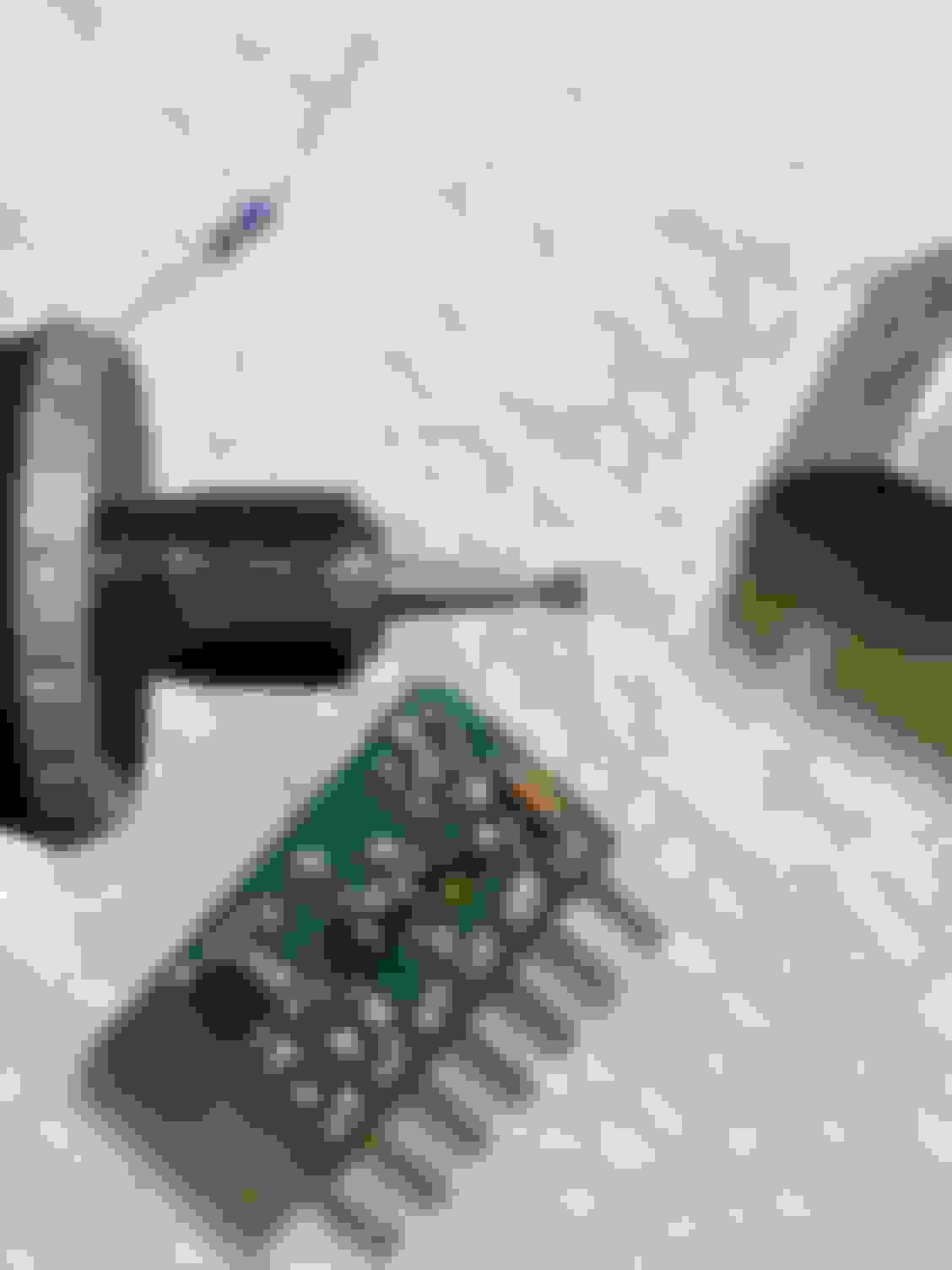
I chose values of 82k ohms and 510 ohms for my voltage divider. In a 12V system, it gives a 74 mV output, which is almost the same as the 79 mV voltage it would read across the shunt from a 3 ohm load (two incandescent bulbs). I decided to cut the trace from pin 7 on the board instead of lifting pin 7 from the chip because I didn't want to risk damaging the chip (the pin could snap off). I labeled a photo with + and - to show where I tapped into the car's power. The photo at the bottom shows the Dremel bit I used to remove the trace from the circuit board. I used a small screwdriver to scrape the green coating off the trace so that I could solder to that area to send pin 7 the voltage from the voltage divider.
Forgive me and don't take this the wrong way but I'm just going to play devil's advocate here: If the original DIY of removing that shunt and replacing it with a resistor were that dangerous, wouldn't there be instances in which that fire issue would have come up by now? I personally have replaced the shunt myself but I am not running any Tritons.
Nevertheless, definitely appreciate you delving into the schematics and providing this new approach though!
Did you tested your idea with replacing that one resistor?
Seems like voltage divider was a way to go anyways. Good that you tried.
thoiboi - I wouldn't say it was dangerous. More like prone to failure, especially if somebody would replace LEDs with standard bulbs and forgot about the modified relay.
Forgive me and don't take this the wrong way but I'm just going to play devil's advocate here: If the original DIY of removing that shunt and replacing it with a resistor were that dangerous, wouldn't there be instances in which that fire issue would have come up by now? I personally have replaced the shunt myself but I am not running any Tritons.
Nevertheless, definitely appreciate you delving into the schematics and providing this new approach though!
Thanks! That's a great question, and I appreciate that. Honestly, in most cases if it were to fail, it would probably just malfunction or stop working. Even if fire sprayed out of the resistor, I doubt it would set your car on fire as long as there isn't anything highly flammable present. Many people are probably not running enough power to cause the resistor to fail but a potential concern is if someone were to use regular bulbs again. That may send too much power through the resistor.
Originally Posted by peter6
Did you tested your idea with replacing that one resistor?
Seems like voltage divider was a way to go anyways. Good that you tried.
thoiboi - I wouldn't say it was dangerous. More like prone to failure, especially if somebody would replace LEDs with standard bulbs and forgot about the modified relay.
I did, haha, and it didn't work. You were right. Ideally, we would want to change the failure voltage detection point so that it could even detect LED bulb failures, but this is good enough for me for now. Thanks again for the idea!
I�ve seen so many threads on LED�s but this is the most recent. Is there a real issue changing all the interior lights to LED�s? I was thinking about doing them all since a few lights are out. I�d prefer to not mess with anything besides a bulb.
 09-09-2019, 12:56 AM