

Switchback Side Markers

 01-17-2009, 08:51 AM
#82
Three Wheelin'
iTrader: (3)
Make your own conductive glue that doesn't require heat and is perfect for use with low current applications such as with LED's:
http://www.instructables.com/id/Make...lue-a-Circuit/

http://www.instructables.com/id/Make...lue-a-Circuit/
01-17-2009, 11:38 AM
#84
Chapter Leader (NY/NJ)
Thread Starter
iTrader: (10)
Make your own conductive glue that doesn't require heat and is perfect for use with low current applications such as with LED's:
http://www.instructables.com/id/Make...lue-a-Circuit/
http://www.instructables.com/id/Make...lue-a-Circuit/
after buda and myself talked about this last night i found this same thing.
"1/4" wide by about 1/16" inch thick will have a resistance of about 32 ohms per inch"
thats not bad for the amount we should be using for the leds
01-17-2009, 04:30 PM
#87
Arggg! Infamouslink, you've done a bad thing. I can't stop working on this. Luckily I have a 3 day weekend. To bad I'll run out of LEDs before it's over. I've modified my layout a little bit. I'm still using copper wire but it looks more like the way your first did it. I'm just creating a small loop with the wire and using that as a tinnning point for the solder, then I just heat it up, supply a little more solder and the LEDs go right on.
Here is the pic of the new setup, I only have the Orange LEDs on the board right now. Since the Orange is 4 times less bright than the white I moved up to 9 Orange LEDs.

The copper wires still loop underneath but they no longer angle to the sides on the top.

Here is the pic of the new setup, I only have the Orange LEDs on the board right now. Since the Orange is 4 times less bright than the white I moved up to 9 Orange LEDs.
The copper wires still loop underneath but they no longer angle to the sides on the top.
01-17-2009, 05:13 PM
#88
Chapter Leader (NY/NJ)
Thread Starter
iTrader: (10)
nice i was thinking the same thing with tinning a copper wire above the connection but in my head it looked a lot worse, your alot better at soldering than me right now lol but i'll get it up to par soon when i start on my second set. Sorry bro i know its addictive as hell. working on the lights and checking AZ all day was my schedule when i was making the lights for like 3 days lol
i like the new boards ima start fabricating my second set after the 3 day weekend. i just came from downstairs and saw the my first set kinda had a dark spot in the middle so im not going to try to combine the ground in the middle so big as i did with my first set and i still plan on using 8 or even 9 leds if i can solder them so close
i like the new boards ima start fabricating my second set after the 3 day weekend. i just came from downstairs and saw the my first set kinda had a dark spot in the middle so im not going to try to combine the ground in the middle so big as i did with my first set and i still plan on using 8 or even 9 leds if i can solder them so close
01-17-2009, 08:38 PM
#89
Guys I am going to go EVEN an easier route. If you look back on Casper's thread you will see I mentioned I used a thinner, cheaper, trimmable LED strip that oznium sells. (This thing is awesome, I still have enough LED units to do like 4 more sidemarkers....and I only spent $10.) I didn't use that more expensive module that everyone else gets. It's been running about 9 months strong now. That strip was so thin and compact that I bet I can squeeze a 2nd strip in there! (I did think of doing a custom switchback at the time but I thought.....nah! too much work!! This thread now got me madd jealous that someone one-upLED'd me....hahaha lol!) SO I am doing this TOTALLY with out soldering/resistor calcs or anything. They also have power leads you can plug into the strip for an easy install. The only bummer is the way I have it wired now looks so professional. I have it so it can utilize the factory harness plug to the exterior. My sidemarker looks factory from the outside. If I am going to have 4 wires out of this thing that will require wires to a relay I am going to have to find a new way to emerge the wires and exit the housing....Not a biggie but all this is so doable in my head.....It will be done by spring!
Last edited by rockyfeller; 01-17-2009 at 08:41 PM.
01-17-2009, 10:50 PM
#93
Chapter Leader (NY/NJ)
Thread Starter
iTrader: (10)
Guys I am going to go EVEN an easier route. If you look back on Casper's thread you will see I mentioned I used a thinner, cheaper, trimmable LED strip that oznium sells. (This thing is awesome, I still have enough LED units to do like 4 more sidemarkers....and I only spent $10.) I didn't use that more expensive module that everyone else gets. It's been running about 9 months strong now. That strip was so thin and compact that I bet I can squeeze a 2nd strip in there! (I did think of doing a custom switchback at the time but I thought.....nah! too much work!! This thread now got me madd jealous that someone one-upLED'd me....hahaha lol!) SO I am doing this TOTALLY with out soldering/resistor calcs or anything. They also have power leads you can plug into the strip for an easy install. The only bummer is the way I have it wired now looks so professional. I have it so it can utilize the factory harness plug to the exterior. My sidemarker looks factory from the outside. If I am going to have 4 wires out of this thing that will require wires to a relay I am going to have to find a new way to emerge the wires and exit the housing....Not a biggie but all this is so doable in my head.....It will be done by spring!
Pictures of stock circuit
 01-19-2009, 06:53 PM
#97
Chapter Leader (NY/NJ)
Thread Starter
iTrader: (10)
if you got the time man. these are hard to make. Buda been missing for the past three days probably making his other set. lol. i did my first set and am going start my second set tomorrow, i'll see how long it takes me from start to finish.
01-20-2009, 02:22 AM
#98
I've been busy but have some pics and a video to post but will do that tomorrow. I ran out of LEDs and just ordered a bunch tonight. I need to finish up my 2nd test board and work on a 3rd one. I've also started prepped 8 boards to be able to build out 4 sets. Mostly just working on getting my build time down. I've also been reading up on etching my own boards as I needed a refresher on that.
Test board 1 (completed): 6 white and 6 orange LEDs. The white really over power the orange. I have more pics and a video of this that I need to post up.
Test board 2 (just need 1 LED to complete): 9 white, 9 orange. I really like the idea of 9 orange LEDs as they are so much dimmer, however It's going to be interesting with doing 9 white LEDs. I may go blind.
Test board 3 (will get done later this week): 6 white, 9 orange. Depending on how the 2nd test board turns out I'm anticipating that this will be the route I go with my lights, however I'll test all 3 with the side marker before making that decision. I'll post up pics and vid with the results. Hopefully that will be next weekend.
Infamouslink, I'm wishing I hadn't seen this thread. It has been expensive. I've upgraded my soldering iron, bought a desolder kit and a soldering station, and a bunch of other things to experiment with on the design.
Also I found an easy to get alternative to my use of the Cat6 wire. Radio shack has 24 gauge tinned wire in a 50ft spool for $5 +/-. I'm now using that as I don't have to strip as much wire any more.
I've also been spending time thinking of the mounting of this and wiring up to the relay. With the 1 amp relay we discussed using, the contacts are fragile so it would be ideal to mount it facing into the assembly and glue to the plexiglass backing we were thinking of going with. Btw, I went to ace hardware and asked them if they had any plexiglass. They went in the back and gave me a scrap piece. That scrap is like big enough to create 50 pieces or more of the size we need.
Ok now I'm rambling so I'll stop at that. Suffice it to say I've been working on this a lot and doing a lot of thinking as to ways to make it faster to make and have an easier install.
Infamouslink and I have done a bit of discussing and sharing of ideas on this to try to improve it and to make this easier to build. I'm hoping Gerzand let's his idea out of the box soon as hopefully it will make this mod easier to do.
01-20-2009, 08:40 AM
#101
Three Wheelin'
iTrader: (3)
Nevermind Buda,
Here is the info for everyone to see
Sorry Ive been so delayed I just haven't had time to get much done due to being at work.
I ordered a pair of 48-LED switchbacks from V-Leds to create each switchback sidemarker. I am using 2 of the longer printed circuit boards (containing 6 white and 6 amber LEDs total) from each bulb. This will essentially be a disassembly\desoldering of the switchback bulb and harvesting of LEDs as well as another board found inside the light. This third board, which is hidden inside the switchback holds a smt digital relay logic chip. This chip is what allows the switchback to turn off the running lights (amber) and turn on the white LED's everytime the turn signal fires. This chip will be wired just as it was in the untouched switchback bulbs so that all of the factory wiring can be used from the headlight's turn signals\running lights and there is no need for an actual relay.
So all in all here are the pro's and con's I see of this method as I see it:
Pro's:
1) Don't have to solder each individual LED.
2) Can wire directly into existing harness.
2) The amber LED's found in the switchback bulbs seem to be brighter (maybe its just me?)
3) Don't have to mess with resistors.
4) The changing of the switchback's flash from amber to white has more of a "digital bounce" (more crisp) look to it because the chip is faster at switching (1 millisecond vs 5m/s for standard relay).
Con's:
1) Still some work in disassembling/desoldering the switchbacks.
2) Price? One pair is 47.99 shipped from v-leds - although you will have alot of spare LED's afterward which COULD be used with relays to make (3) more pairs.
3)There is a reputation for the chips to blow out after about a year. I haven't experienced this yet but I've heard its been unique to autolumination.com's bulbs.
Hopefully I will have this all wired up by this weekend but still need to buy a new pair of sidemarkers because i don't want to cut up my beautiful white color blinking set I just made a month ago. I'll probably just sell them once I get my switchback set made up.
Hope this was of some value to someone.
I'm not trying to heavily persuade anyone into doing it as I am. I just had this idea from the beginning and I stuck with it.
Last edited by gerzand; 01-20-2009 at 08:44 AM.
01-20-2009, 09:22 AM
#102
Chapter Leader (NY/NJ)
Thread Starter
iTrader: (10)
I've been busy but have some pics and a video to post but will do that tomorrow. I ran out of LEDs and just ordered a bunch tonight. I need to finish up my 2nd test board and work on a 3rd one. I've also started prepped 8 boards to be able to build out 4 sets. Mostly just working on getting my build time down. I've also been reading up on etching my own boards as I needed a refresher on that.
Test board 1 (completed): 6 white and 6 orange LEDs. The white really over power the orange. I have more pics and a video of this that I need to post up.
Test board 2 (just need 1 LED to complete): 9 white, 9 orange. I really like the idea of 9 orange LEDs as they are so much dimmer, however It's going to be interesting with doing 9 white LEDs. I may go blind.
Test board 3 (will get done later this week): 6 white, 9 orange. Depending on how the 2nd test board turns out I'm anticipating that this will be the route I go with my lights, however I'll test all 3 with the side marker before making that decision. I'll post up pics and vid with the results. Hopefully that will be next weekend.
Infamouslink, I'm wishing I hadn't seen this thread. It has been expensive. I've upgraded my soldering iron, bought a desolder kit and a soldering station, and a bunch of other things to experiment with on the design.
Also I found an easy to get alternative to my use of the Cat6 wire. Radio shack has 24 gauge tinned wire in a 50ft spool for $5 +/-. I'm now using that as I don't have to strip as much wire any more.
I've also been spending time thinking of the mounting of this and wiring up to the relay. With the 1 amp relay we discussed using, the contacts are fragile so it would be ideal to mount it facing into the assembly and glue to the plexiglass backing we were thinking of going with. Btw, I went to ace hardware and asked them if they had any plexiglass. They went in the back and gave me a scrap piece. That scrap is like big enough to create 50 pieces or more of the size we need.
Ok now I'm rambling so I'll stop at that. Suffice it to say I've been working on this a lot and doing a lot of thinking as to ways to make it faster to make and have an easier install.
Infamouslink and I have done a bit of discussing and sharing of ideas on this to try to improve it and to make this easier to build. I'm hoping Gerzand let's his idea out of the box soon as hopefully it will make this mod easier to do.
Test board 1 (completed): 6 white and 6 orange LEDs. The white really over power the orange. I have more pics and a video of this that I need to post up.
Test board 2 (just need 1 LED to complete): 9 white, 9 orange. I really like the idea of 9 orange LEDs as they are so much dimmer, however It's going to be interesting with doing 9 white LEDs. I may go blind.
Test board 3 (will get done later this week): 6 white, 9 orange. Depending on how the 2nd test board turns out I'm anticipating that this will be the route I go with my lights, however I'll test all 3 with the side marker before making that decision. I'll post up pics and vid with the results. Hopefully that will be next weekend.
Infamouslink, I'm wishing I hadn't seen this thread. It has been expensive. I've upgraded my soldering iron, bought a desolder kit and a soldering station, and a bunch of other things to experiment with on the design.
Also I found an easy to get alternative to my use of the Cat6 wire. Radio shack has 24 gauge tinned wire in a 50ft spool for $5 +/-. I'm now using that as I don't have to strip as much wire any more.
I've also been spending time thinking of the mounting of this and wiring up to the relay. With the 1 amp relay we discussed using, the contacts are fragile so it would be ideal to mount it facing into the assembly and glue to the plexiglass backing we were thinking of going with. Btw, I went to ace hardware and asked them if they had any plexiglass. They went in the back and gave me a scrap piece. That scrap is like big enough to create 50 pieces or more of the size we need.
Ok now I'm rambling so I'll stop at that. Suffice it to say I've been working on this a lot and doing a lot of thinking as to ways to make it faster to make and have an easier install.
Infamouslink and I have done a bit of discussing and sharing of ideas on this to try to improve it and to make this easier to build. I'm hoping Gerzand let's his idea out of the box soon as hopefully it will make this mod easier to do.
Yes, Yes, Yes, and my bad. lol i also upgraded and bought a whole solder station and everything else. it'll pay for itself in the long run. Cant wait to see the videos. i was gonna start another set today but cant got to take care of some stuff at the DMV so i'll probably be out all day. i'll look into the tinned wired from radioshack, that probably would be the way to go. good score on the plexiglass, home depot had it for 4 bucks an 11 X14 so im good. i was the same thign always thinking about how to make thigns better of the light and how i am gonna just start creating stuff from scratch with the little leds and my whole new soldering station so for that i say my bad, its worse than crack.
01-20-2009, 09:34 AM
#103
Ah ha! I knew it had to be a non-mechanical relay of some sort. That's a good idea looking at utilizing the switch backs.
You are correct on the brightness being more. According to the specs from v-leds:
Single LED Intensity: 1250-1600 mcd (most likely orange - white respectively)
Oznium PLCC-2 LEDs:
White - 850 mcd typical
Orange - 190 mcd typical
That means this would make for an extremely bright set. I definitely like that mcd rating for the orange color, but not sure about the white being that bright on the sides. It may attract unwanted attention but of course that is a personal preference. The Oznium white LED module that everyone has used to date uses the PLCC-2 LEDs so the setup using the v-leds switchbacks as a source would be twice as bright as the oznium module for white. I'll have to pay attention today to see the brightness of them during day/night to try to get an idea of what it would look like. To bad it is overcast today.
I have the auto-illumination ones. I have the problem in which it does not blink orange all the time on the switchbacks. I always notice it on the left blinker as you usually have to wait longer at the light for a left hand turn. I've been meaning to switch the sides for the switchbacks to test out the other one to see if it also happens. It usually only happens when the lights are cold and have not had time to warm up but I've seen it happen in the summer too.
Anyone have this problem with the ones from v-leds.com? This could be of concern for this mod.
01-20-2009, 09:46 AM
#104
Chapter Leader (NY/NJ)
Thread Starter
iTrader: (10)
Nevermind Buda,
Here is the info for everyone to see
Sorry Ive been so delayed I just haven't had time to get much done due to being at work.
I ordered a pair of 48-LED switchbacks from V-Leds to create each switchback sidemarker. I am using 2 of the longer printed circuit boards (containing 6 white and 6 amber LEDs total) from each bulb. This will essentially be a disassembly\desoldering of the switchback bulb and harvesting of LEDs as well as another board found inside the light. This third board, which is hidden inside the switchback holds a smt digital relay logic chip. This chip is what allows the switchback to turn off the running lights (amber) and turn on the white LED's everytime the turn signal fires. This chip will be wired just as it was in the untouched switchback bulbs so that all of the factory wiring can be used from the headlight's turn signals\running lights and there is no need for an actual relay.
So all in all here are the pro's and con's I see of this method as I see it:
Pro's:
1) Don't have to solder each individual LED.
2) Can wire directly into existing harness.
2) The amber LED's found in the switchback bulbs seem to be brighter (maybe its just me?)
3) Don't have to mess with resistors.
4) The changing of the switchback's flash from amber to white has more of a "digital bounce" (more crisp) look to it because the chip is faster at switching (1 millisecond vs 5m/s for standard relay).
Con's:
1) Still some work in disassembling/desoldering the switchbacks.
2) Price? One pair is 47.99 shipped from v-leds - although you will have alot of spare LED's afterward which COULD be used with relays to make (3) more pairs.
3)There is a reputation for the chips to blow out after about a year. I haven't experienced this yet but I've heard its been unique to autolumination.com's bulbs.
Hopefully I will have this all wired up by this weekend but still need to buy a new pair of sidemarkers because i don't want to cut up my beautiful white color blinking set I just made a month ago. I'll probably just sell them once I get my switchback set made up.
Hope this was of some value to someone.
I'm not trying to heavily persuade anyone into doing it as I am. I just had this idea from the beginning and I stuck with it.
Here is the info for everyone to see
Sorry Ive been so delayed I just haven't had time to get much done due to being at work.
I ordered a pair of 48-LED switchbacks from V-Leds to create each switchback sidemarker. I am using 2 of the longer printed circuit boards (containing 6 white and 6 amber LEDs total) from each bulb. This will essentially be a disassembly\desoldering of the switchback bulb and harvesting of LEDs as well as another board found inside the light. This third board, which is hidden inside the switchback holds a smt digital relay logic chip. This chip is what allows the switchback to turn off the running lights (amber) and turn on the white LED's everytime the turn signal fires. This chip will be wired just as it was in the untouched switchback bulbs so that all of the factory wiring can be used from the headlight's turn signals\running lights and there is no need for an actual relay.
So all in all here are the pro's and con's I see of this method as I see it:
Pro's:
1) Don't have to solder each individual LED.
2) Can wire directly into existing harness.
2) The amber LED's found in the switchback bulbs seem to be brighter (maybe its just me?)
3) Don't have to mess with resistors.
4) The changing of the switchback's flash from amber to white has more of a "digital bounce" (more crisp) look to it because the chip is faster at switching (1 millisecond vs 5m/s for standard relay).
Con's:
1) Still some work in disassembling/desoldering the switchbacks.
2) Price? One pair is 47.99 shipped from v-leds - although you will have alot of spare LED's afterward which COULD be used with relays to make (3) more pairs.
3)There is a reputation for the chips to blow out after about a year. I haven't experienced this yet but I've heard its been unique to autolumination.com's bulbs.
Hopefully I will have this all wired up by this weekend but still need to buy a new pair of sidemarkers because i don't want to cut up my beautiful white color blinking set I just made a month ago. I'll probably just sell them once I get my switchback set made up.
Hope this was of some value to someone.
I'm not trying to heavily persuade anyone into doing it as I am. I just had this idea from the beginning and I stuck with it.
quick questions-
how can this be wired with original harness? you need a third wire for amber. so you will still need to run a wire from the blink signal to the side marker, thru the back panel, and into the base of the chip.
after taking apart the switchback, the board that you are using with 6 leds will still need a resistor, how is that looking since i never took apart i switchback dont know how it looks. what resistors are the switchbacks using? i ask becuz in a series circuit, resistance is additive and in a parellel its a whole different scenerio. i know the switchbacks are wired in a series parellel circuit using 1 resistor per color and about 6-8 leds boards in parellel. does anyone have the specs on the PLCC-2 lights that come in the switchbacks?
usually white will have a voltage drop of around 3 since its the brightest color so in a series circuit with the one resistor, having 6 leds will not provide full voltage to each light and current, depending on the resistor they used, will be off as well.
will the chip fit inside the side marker housing?
the leds boards taken off the switchback how are you going to mount them inside the side marker?
if and when you take apart the light, can you see whats the voltage drop of one WHITE led?
looks good tho more on the expensive note plus i think its quite around the same amount of work with desoldering, soldering,wiring, making it fit, running cable. buying the lights at $0.49, the board at $4.49 and soldering just seems to better for myself ( and buda)
Good luck
01-20-2009, 10:09 AM
#105
Three Wheelin'
iTrader: (3)
how can this be wired with original harness?
From above: "This chip will be wired just as it was in the untouched switchback bulbs so that all of the factory wiring can be used from the headlight's turn signals\running lights and there is no need for an actual relay"
after taking apart the switchback, the board that you are using with 6 leds will still need a resistor, how is that looking since i never took apart i switchback dont know how it looks. what resistors are the switchbacks using? i ask becuz in a series circuit, resistance is additive and in a parellel its a whole different scenerio. i know the switchbacks are wired in a series parellel circuit using 1 resistor per color and about 6-8 leds boards in parellel.
Good point, I probably will have to take into account the fact that since all 48 led's wont be used in each sidemarker, ill have to adjust the resistance.
will the chip fit inside the side marker housing?
yes, its smaller than your pinky finger nail
the leds boards taken off the switchback how are you going to mount them inside the side marker?
since they are already soldered to their own board, I use the same method that has been used with the oznium LED modules... double side tape the smaller boards to the original sidemarker board.
if and when you take apart the light, can you see whats the voltage drop of one WHITE led?
I can for you.
looks good tho more on the expensive note plus i think its quite around the same amount of work with desoldering, soldering,wiring, making it fit, running cable. buying the lights at $0.49, the board at $4.49 and soldering just seems to better for myself ( and buda)
good, keep on going at it. when mine is done ill post pics. until then, good luck with your improvements to your design.
01-20-2009, 10:37 AM
#106
Hey gerzand, thanks a lot for letting us know how you are doing it. This has opened up some options. I'm really interested in the relay the the switchback uses. Could you tell us if there is any printing on it that may identify the part number or manufacturer? Really anything that would help to identify where we could buy some directly.
01-20-2009, 11:05 AM
#107
Three Wheelin'
iTrader: (3)
Hey gerzand, thanks a lot for letting us know how you are doing it. This has opened up some options. I'm really interested in the relay the the switchback uses. Could you tell us if there is any printing on it that may identify the part number or manufacturer? Really anything that would help to identify where we could buy some directly.
In the meantime, I found that the proper terminology for these chips is "Solid-State Relay" and there are a variety of 12v compatible SSR's available on the internet. The DIP type package design seem to be the be the best if you were looking to solder straight to a set of terminals. They should have no issue fitting inside the sidemarker. Overvoltage protection (a common feature) to a chip is a MUST because if one of these chips go bad they can wreak havoc on your electrical system.
 01-20-2009, 02:41 PM
#108
Sure, ill post up some pics once I get to taking it apart this week...Although im almost positive its going to be blank.
In the meantime, I found that the proper terminology for these chips is "Solid-State Relay" and there are a variety of 12v compatible SSR's available on the internet. The DIP type package design seem to be the be the best if you were looking to solder straight to a set of terminals. They should have no issue fitting inside the sidemarker. Overvoltage protection (a common feature) to a chip is a MUST because if one of these chips go bad they can wreak havoc on your electrical system.
In the meantime, I found that the proper terminology for these chips is "Solid-State Relay" and there are a variety of 12v compatible SSR's available on the internet. The DIP type package design seem to be the be the best if you were looking to solder straight to a set of terminals. They should have no issue fitting inside the sidemarker. Overvoltage protection (a common feature) to a chip is a MUST because if one of these chips go bad they can wreak havoc on your electrical system.
On another note the specs on the switchback LEDs is very interesting. The current draw is rated at 360 mA and with 24 LEDs lighting up at once that means 15mA per LED. How the heck is it so much brighter then when the oznium ones are at 20mA current draw? I've been searching for other places to get PLCC-2 style LEDs and have found places to get ones with 1500mcd on the white ones, however the best I found for orange so far is 500mcd.
I would look more but I need to work now. ha ha
01-20-2009, 04:29 PM
#109
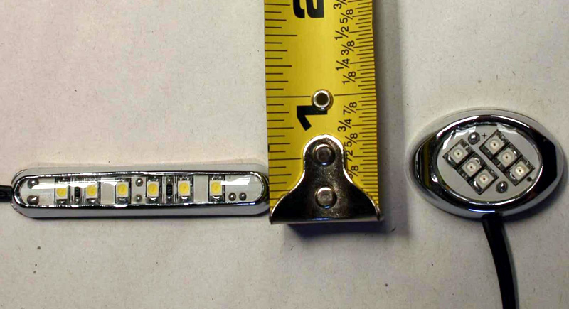
Yeah this is the module everyone gets. This is the one I was saying I DIDN'T use. I wanted to try something different. I did a much more simpler and cheaper route.
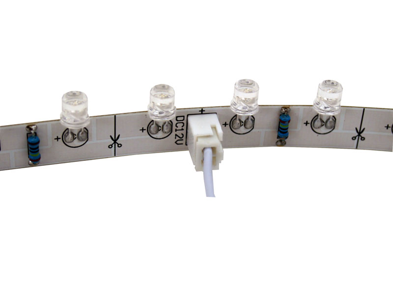
http://www.oznium.com/led-strip-flat-head
I used these strips and cut them into small sections and they fit! The smallest section is 3 LEDs long and it was wired independently and it worked out! Running strong for almost a year now. The wiring was soldered into the contacts of the original circuit board so it simply plugs into the car's wiring.
Only problem is, oznium does not sell them in amber! They have yellow but that won't match! They need to be more orange to match the front switchbacks. I still have some parts of the strips sitting here. I feel like desoldering the white LEDs off of it and soldering in some loose 3mm amber LEDs onto it. It should work out. I just need some strip holders and power connectors for them.
Last edited by rockyfeller; 01-20-2009 at 04:31 PM.
01-20-2009, 05:37 PM
#111
Chapter Leader (NY/NJ)
Thread Starter
iTrader: (10)
looks like everybody got something going. thats real good.
buda how much they wanted for the plcc-2 white leds 1500mcd?
rocky- i see where you going with this. you could do the same thing we doing with the leds instead of the plcc-2 lights.
buda how much they wanted for the plcc-2 white leds 1500mcd?
rocky- i see where you going with this. you could do the same thing we doing with the leds instead of the plcc-2 lights.
01-20-2009, 11:11 PM
#112
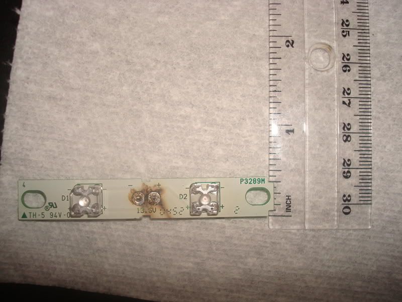
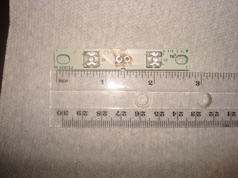
Here's a pic of the 1st test board all wired up for the video

Here's a pic of the second test board, if only there was another LED...

And here's a link to the video of the 1st test set in action:
http://img531.imageshack.us/img531/9...4103543lg9.flv
Here's a pic of the second test board, if only there was another LED...
And here's a link to the video of the 1st test set in action:
http://img531.imageshack.us/img531/9...4103543lg9.flv
01-20-2009, 11:20 PM
#113
http://www.marktechopto.com/Products...0%20AND%205000
01-21-2009, 12:03 AM
#114
Chapter Leader (NY/NJ)
Thread Starter
iTrader: (10)
damn bro sorry about that 1 missing LED LMAO i know you were pissed. i still got my shipment in the box haven't had the "care" to open it. it looks good tho. i couldn't see the video .flv? can you post it up somewhere so i could see it. how does it look? what are your thoughts about it? you have a real clean setup. where you plan on putting the relay if you end up using it?
 01-21-2009, 12:13 AM
#116
Chapter Leader (NY/NJ)
Thread Starter
iTrader: (10)
nice!! looks just like my first video LMAO. same setup 6 X 6 leds. i want to see the 9 led setup. take one of the lights off the 6X6 and solder it on the 9 by 9. did you use 3 resistors for each color?
01-21-2009, 12:28 AM
#118
Chapter Leader (NY/NJ)
Thread Starter
iTrader: (10)
You the man!! and bro tell everybody thats waiting for you to do something ( wife, kids, family) that im sorry i started you off in the project. i know i had to apologize to the wife for a day or two. and i haven't worked on the car since!! CRACK CRACK CRACK CRACK CRACK