When you click on links to various merchants on this site and make a purchase, this can result in this site earning a commission. Affiliate programs and affiliations include, but are not limited to, the eBay Partner Network.
G-100: DIY LED Interior Part VII: Front Driver Door w/ RL Door-Handle LED!
Seven, shooter, lucky number seven...yeah, no not at all. We've been honest with each other, so let's keep it real: this door is a BEAST. Make no two ways about it. Performing this mod will test require you to utilize every method you've learned in the previous mods, so consider this to be your final exam, kids. Set some serious time aside, this one takes awhile.
Thanks go to dwb993 for specifying the exact bulbs to use.
LET'S GO! TOOLS NEEDED
Flat head screwdriver
Dremel w/ cutting wheel
Soldering Iron
MATERIALS
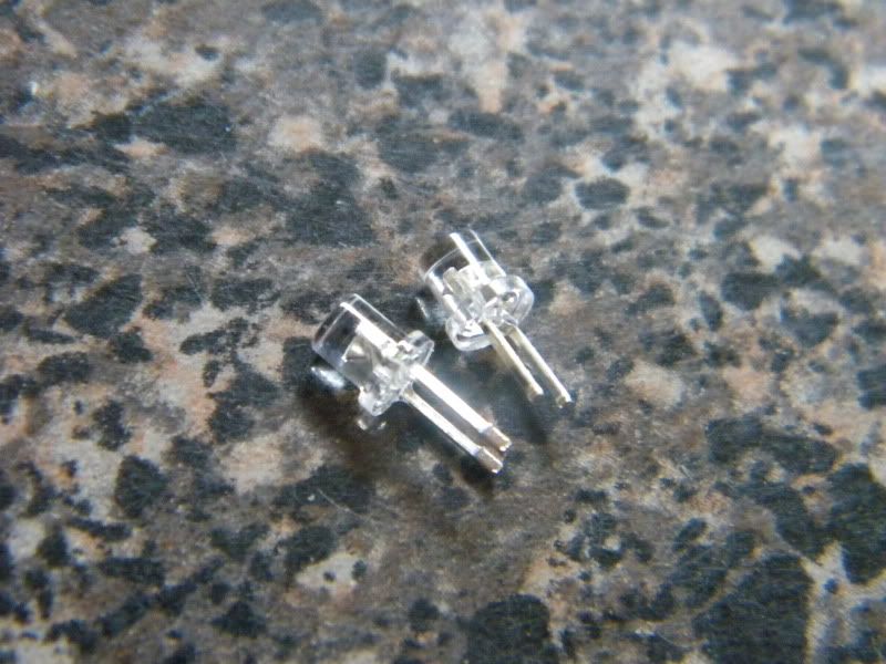
8 x 3mm bulb to your liking...I am used wide-angle flat headed 3mm bulbs
5 x PLCC-2 style LED bulb
Solder
FLUX, I CANNOT STRESS THIS ENOUGH
2.2k-ohm resistor
TIME
Plug-and-play method - 240minutes or more with troubleshooting
STEP I - GETTIN' TO THE GOOD STUFF
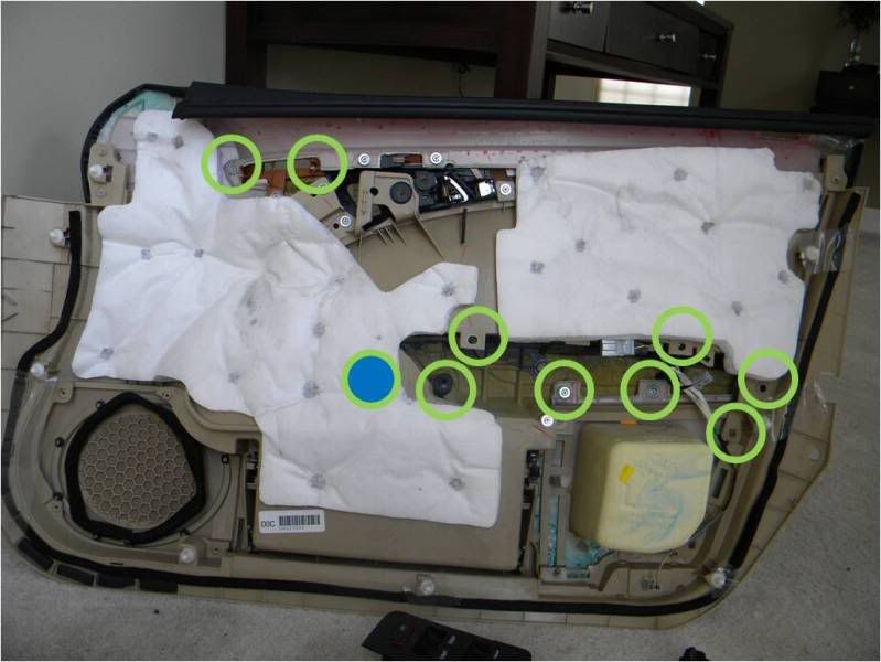
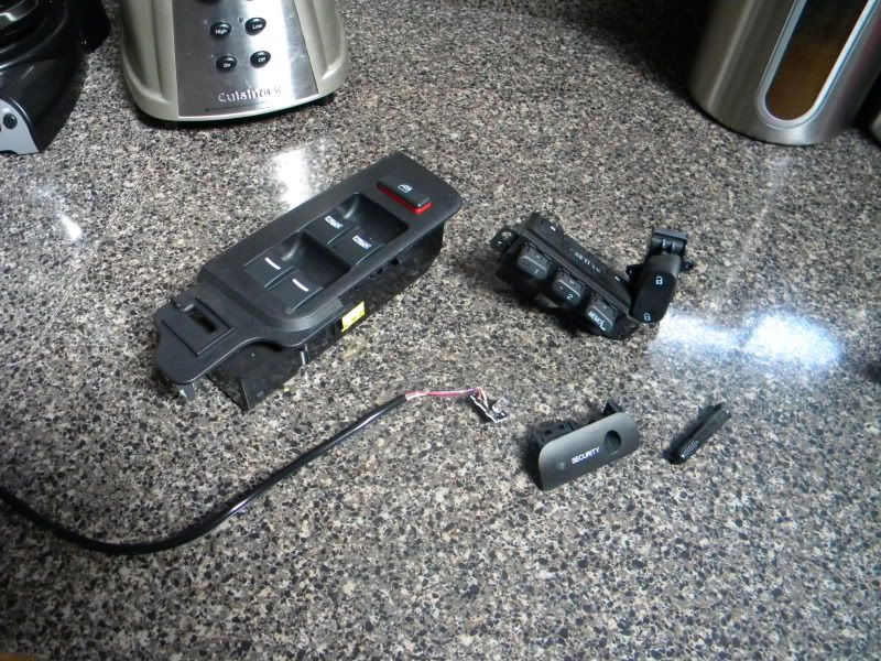
Ok, we'll start off by popping off zee OE paneling and pulling the necessary circuits. I have highlighted the screws that need to be removed in order to get those buggers out.
STEP II - LOCK SWITCHES
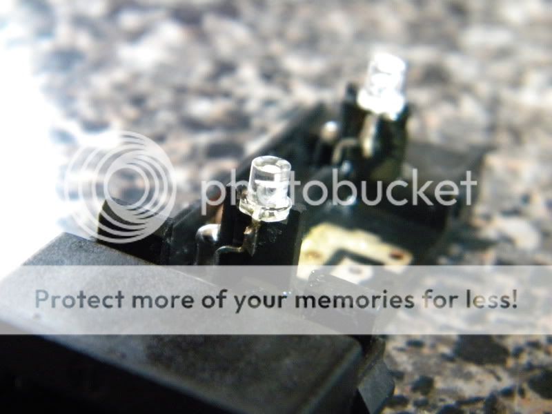
We're going to start with the lock switch, piece of cake. You can pop the cover off with your thumbs, it's quite simple. SO, what have we here? Ah, yes, I spy, with my little eye, two 3mm LEDs that don't quite fit the color code of our little club, so I will have to play the role of bouncer and evict them post haste...only thing is, in this club, violation of the rules are punishable by Dremel beheading.
Snip the LEDs and solder in to position. Simple.
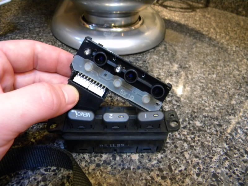
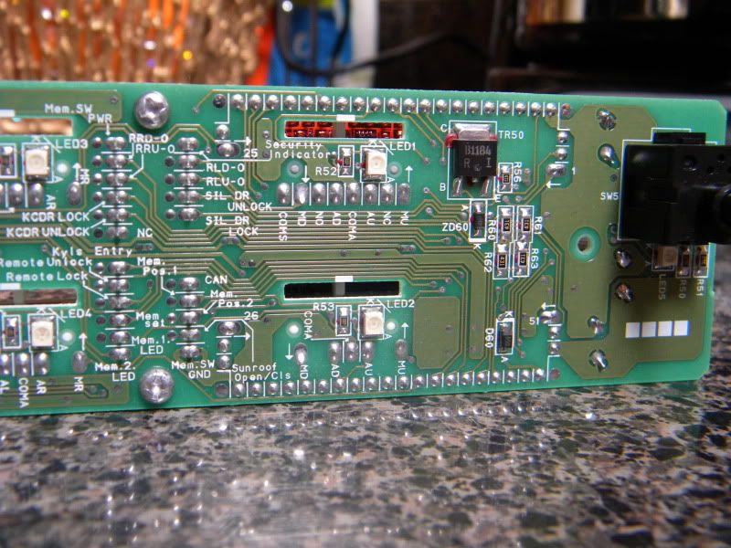
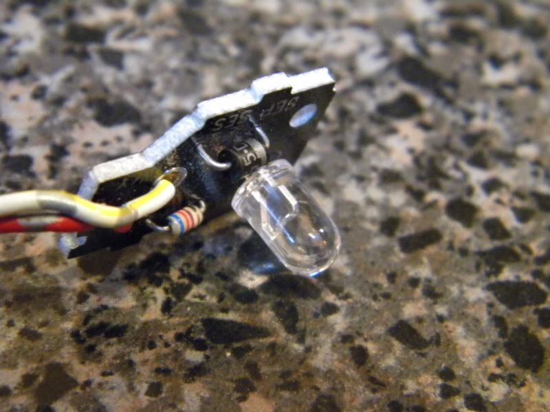
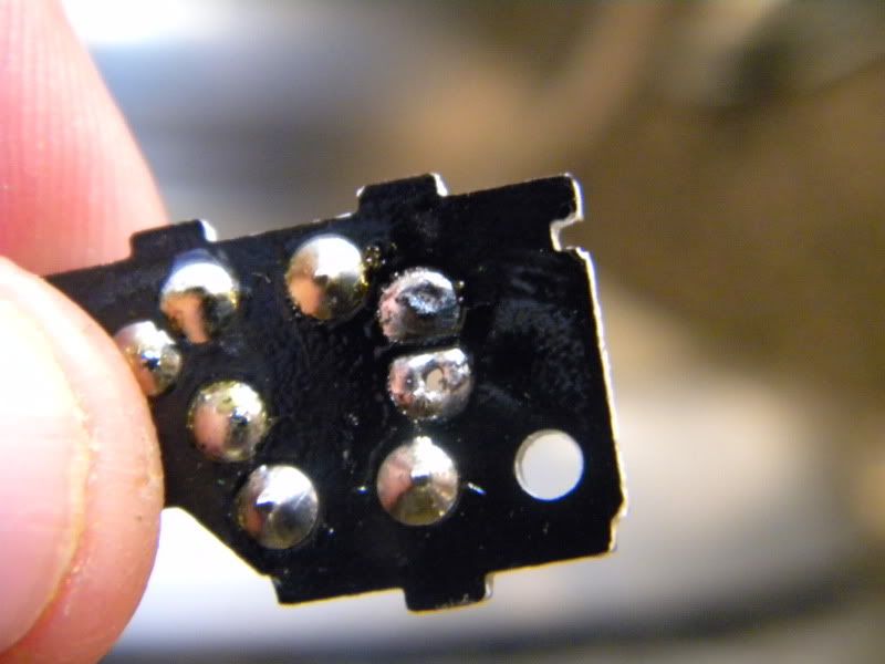
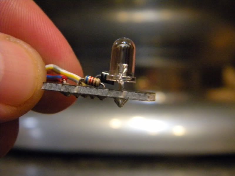
STEP III - MEMORY SEAT SWITCHES
Hell yeah, man. We're going to have some fun with this one. Ok, now, on the back you'll see three bayonet-style bulbs, simple as anything seeing as how you've done this before.
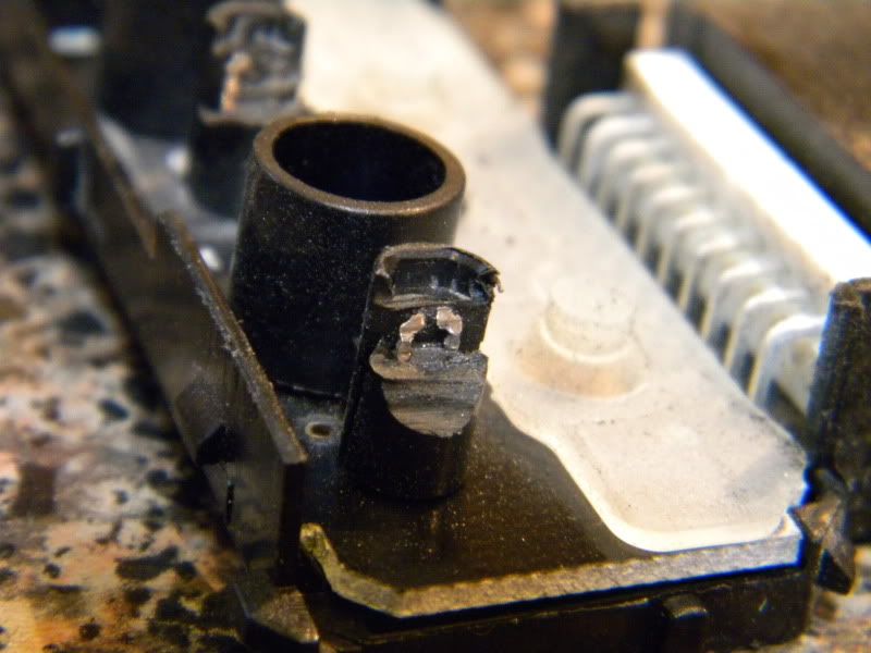
Then we've got a bigger challenge to overcome...see those two little illumination buggers. "They're nested in there deeper then an Alabama Tick" (hero award given to whomever can give me the awesome source of that quote) OK, well, how are we going to get to it? Well, YOU KNOW THE ANSWER! Shave, shave, shave away, cut, and solder.
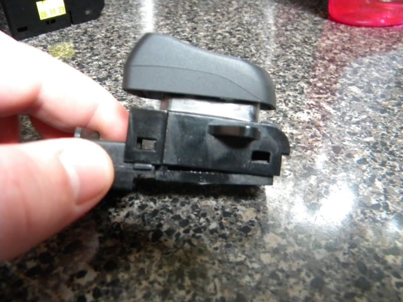
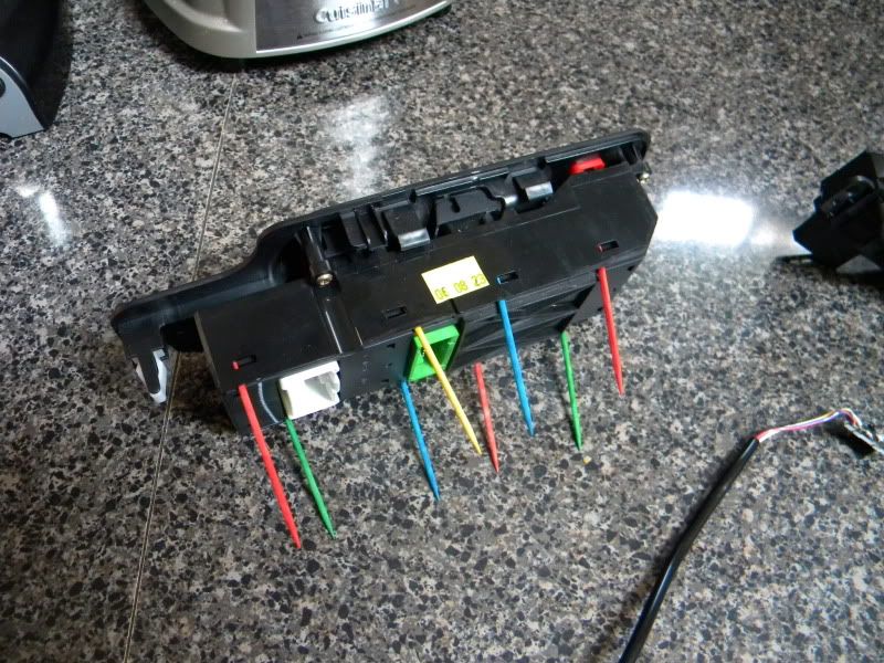
STEP IV - DOOR CONTROL SWITCHES
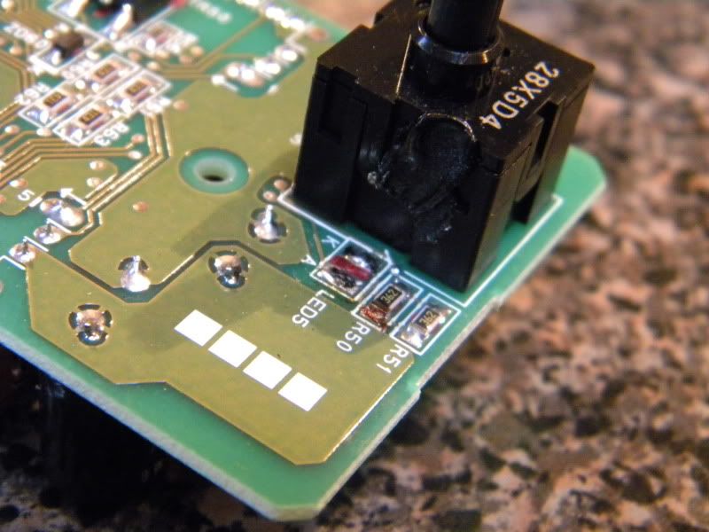
Window switch time. Ah, the PLCC-2 style LED. No fears, though! I used super fancy toothpicks to pry this sucker open, honestly, it's MUCH easier then using a screwdriver, or a small army of them. Ok, so, we're going to apply copper braid to the solder connections to adsorb the flux, then pop a new one in. NOW, make sure you pay attention to the location of the cathode end! It will be the side with the little corner notation. It will face the upper left hand side on the board. PROTIP: You don't have to replace the PLCC-2 with a PLCC-2, you can use a 3mm LED instead, but I will leave that choice up to you. Now, here's the catch, DO NOT, DO NOT(!!!) overheat the flux. If you do, chances are good you will overheat the LED and fry the internals. I learned this the hard way. So have at it!
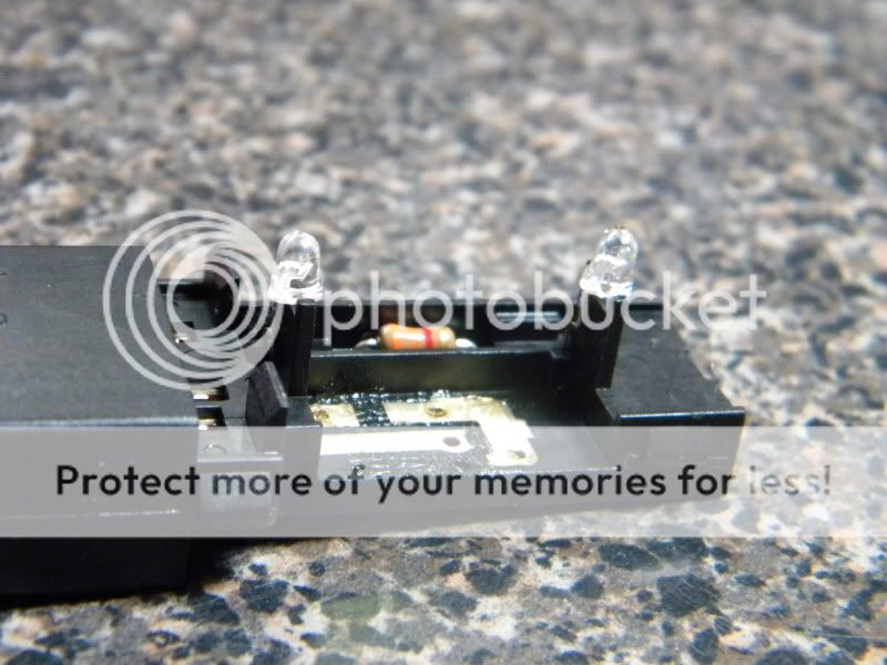
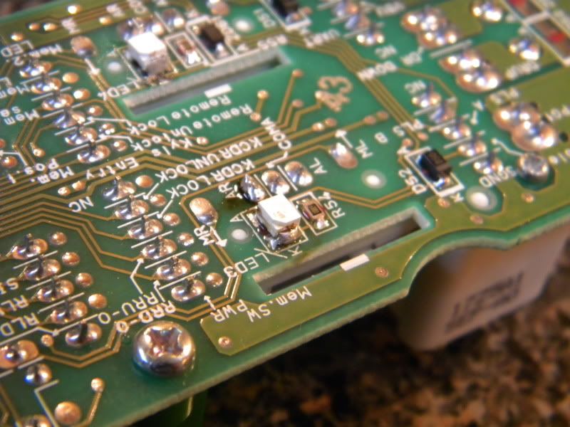
STEP V - KEEP IT TO YOURSELF
You know, you'd think that when coming across a single LED that it'd be real easy, right? *BZZZZT, WRONG!* I always test the OE LEDs before doing any work, and here's why: once in awhile, you run across LEDs where the wide end of the filament is the anode; this is one of them. Just place the tip of the iron between the pins, heat, and pull. Cut, heat, and replace...not forgetting you may need to flip your LED leads!
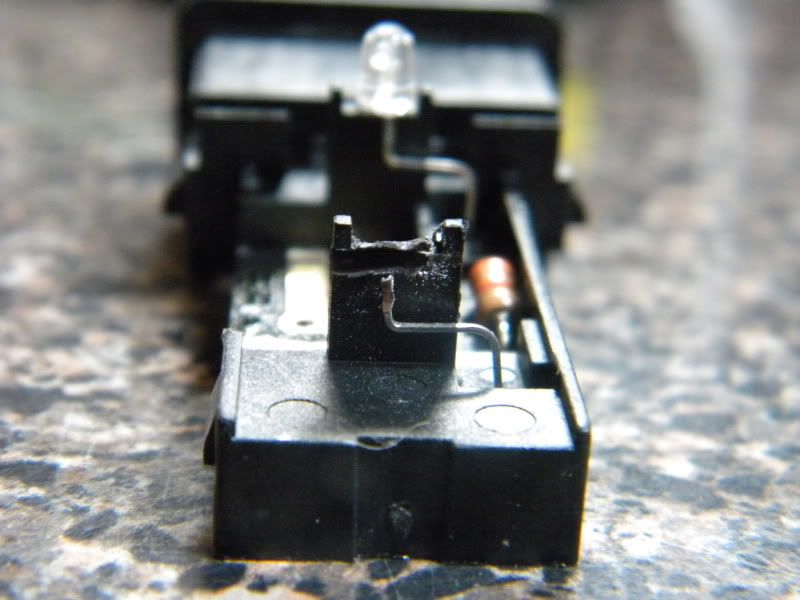
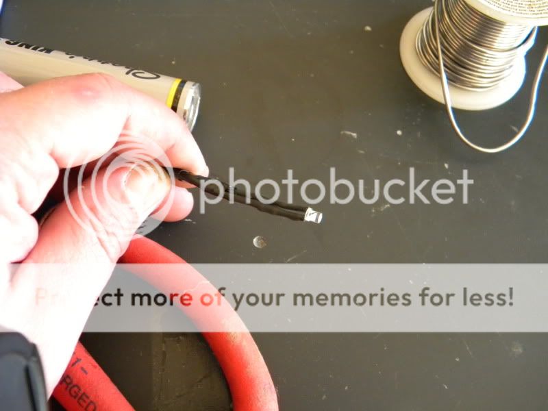
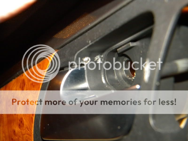
STEP VI - RL, TL, LED-L
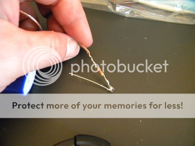
During my test drives of the TL and RL, I really did appreciate the blue backlight of the door handle, so I thought, "Why let them have all the fun?" So, what we're going to do is rain on their parade and have the same. Prepare an LED by attaching the 2.2k-ohm resistor to the cathode end, solder, shrink, and tape. We're using 2.2k-ohm because we want this to be SUBTLE. You're going to wire the negative to BLACK and the positive to the GREEN wire with a WHITE stripe that features the double-band of SILVER.
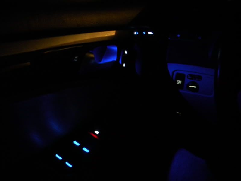
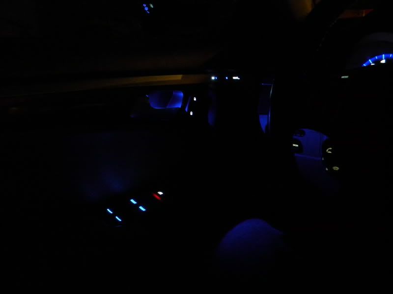
STEP VII - UHHHH...WTF?!
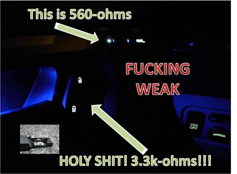
Well, as I have noted before, I SUCK at taking nighttime pics, so these shots are wayyyy brighter then it is in actuality. BUT, one thing is incredibly clear...in spite of using the same LEDs throughout, the lock switch is relativley dim?! Hmmm, what kind of resistor did Acura put in there? Ok, so I would use a 470-ohm resistor for 2 LEDs...let's take a look at the bands...HOLY SHIT, 3.3k-ohm??!?!?! DAMMIT. Well, looks like I will have to go back and swap the LED here. Ugh. So close. Here's some shots nonetheless.
I'll try to fix the resistor this week, although it looks quite unlikley I will have time to do so. Next up will be the knee-panel, although that should be a fly-by job, for if I had to guess, it's bayonet city in there. More to come!
Ummm, that quote was from Jesse "The Body" Ventura in Predator!
Another quality job from DeathMetal. Way to go, dude!
Those window switch LEDs are bright as hell---I can see you have the same glow on the door panel as I got with mine.
Wow ive seen pretty much all of your DIYs and all i can say is, holy shit! you have some serious gonads my friend. But good work i bet the whole thing completed looks really good. congrats
Wow ive seen pretty much all of your DIYs and all i can say is, holy shit! you have some serious gonads my friend. But good work i bet the whole thing completed looks really good. congrats
Thanks, man, I appreciate it! It�s really starting to come together now, I am mixing the blue and white together and it looks AWESOME to see the same color schematic from the gauges flowing in to the rest of the car. I might try and get the center console done over Thanksgiving�
Ummm, that quote was from Jesse "The Body" Ventura in Predator!
Another quality job from DeathMetal. Way to go, dude!
Those window switch LEDs are bright as hell---I can see you have the same glow on the door panel as I got with mine.
Thanks, Dave! Yes, you are indeed the winner, quote well quoted, haha. Everything looks to a be a bit brighter then it is in person, I can thank my crappy skills as a photographer for that one. I still need to go back and fix that resistor issue as it really is driving me batshit crazy. Gotta admit, though, for the glow that exists, I love every bit of it!
I�m gonna shoot you a PM later on today about the steering wheel and center stack�
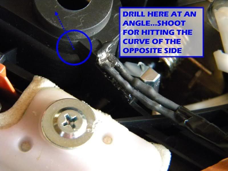
Did you drill the hole for the LED from the front of the panel or from the back.
Drill from the rear - you won't be able to pull a true angle if you tap from the front. This is critical as you need to ensure the LED reflects off of the recessed portion of the handle.
Go for it, man...of all the LED mods I've done thus far, this is still probably my favorite, it really adds a killer touch.
you have a lot of time on your hands but all these DIYS are awesome. wish i had the skills to do it. i dont even understand any of it lol
I wish, man. I'm one of those people that can't sit still and always has to be doing something. I don't watch TV at all, so while you're relaxing and just chilling out, I'm probably running around working on the house/car :P
Thanks for the compliment, but really, this stuff is way easier then you'd imagine, you just need to bit the bullet and do it!
Do you have a pick of where you drilled the hole in the back.Want to try this mod but don't want the hole to come out in the wrong place since it looks like a one shot deal.
Do you have a pick of where you drilled the hole in the back.Want to try this mod but don't want the hole to come out in the wrong place since it looks like a one shot deal.
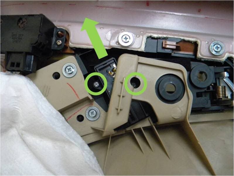
Here ya go. Not a one shot deal, I chose the wrong spot the first time.
I hate to bump all of the threads, but there is an important item that needs to be noted; some of the white LEDs have been burning out, which can be attributed to one thing and one thing only: thermal overload. Therefore,
IT IS HIGHLY RECOMMENDED THAT A 1K-OHM RESISTOR BE USED FOR ALL WHITE LEDS.
I have begun the process of replacing LEDs/resistors for the dearly-departed and can state that the new resistors seem to do the trick.
I know that DeathMetal doesn't lurk on the forum too much anymore, but I'm bumping his thread from 2009 to see if any other electronic gurus can help me out.
I worked on this project last night and ran across the dim lock switches as well. The blue LEDs that I've been using were much dimmer and more violet looking due to the OEM 3.3K ohm resistor. Per OPs original post, it appears that a 560 OEM resister is used in the memory switches and he said that he would have replaced the 3.3k ohm resister with a 470 ohm resister.
Has anyone replaced the lock switch resistor before or have a suggestion as to which one would work better (560 or 470)? This is definitely not my forte, so any suggestions are welcomed.
Here are a few pictures for reference (PS- After this I only have the steering wheel left!):
So I purchased both a 470 ohm resistor and a 540 ohm resistor. I think I'm going to start with the 470 ohm resistor and see how that looks first. Then, if more resistance is needed, I will swap in the 540 resistor.
Your problem is not with your resistor values but with the quality of the LEDs. To create a blue led, there's a deposit of Indium Nitride and Gallium Nitride on the collector cell; how these deposits are lined up will determine the color output of the LED. Lower quality LEDs will emit UV/purple whereas higher quality LEDs have properly doped the collector to provide the real blue.
I went though around 5 different sellers until I found one I like, then purchased around 500 blue LEDs just so I had enough. Playing with resistors will only frustrate you; you have either a bad LED, several bad LEDs, or a bad batch. Kudos for trying to overcome this with resistor values, but you're barking up the wrong tree.
DeathMetal, thanks for all the excellent write ups here!
with regards primarily to the HVAC/touchscreen illumination, Acura uses 2-3 different value incandescent bulbs. Has anyone here experimented with resistor values to get the brightness correct for the hvac leds that illuminate either a single button or a pair of buttons?
if so, what value resistors did you end up using?
also, I see that there�s 2 dimmer controllers in the car. 1 for the factory leds and the other for the incandescent bulbs. I assume that�s because of the nonlinear dimming characteristic of led. After swapping out all the factory bulbs, has anyone disconnected the incandescent dimmer and jumped the led dimmer into all the bulbs to see what effect this has?
how does the brightness of the leds, in the a/c controls with leds compare to that of the factory bulbs? I know a lot of guys like their stuff BRIGHT, but I don�t. I wish the gauges would get about 50% dimmer than the lowest setting. I like the cabin Dark at night. Any comments on this?
I believe I used 5.1k resistors with clear white through-hole 3mm LEDs for the top buttons on the HVAC controls. That's been a good match for the brightness of the factory bulbs (It's a different color, but that was intentional).
Auto/up/down and the roof controls are LED, the rest is stock:


 11-01-2009, 09:19 PM


 I don't watch TV at all, so while you're relaxing and just chilling out, I'm probably running around working on the house/car :P