[DIY] Let's Add Some Class: Footwell LED Lighting
#201
Starcraft II addict
iTrader: (1)
Ran out of edit time and couldn't update prior post. Please use this one instead as I added more details regarding the switch.
It depends on how you have them wired. (I haven't read the install in a long time so don't remember it)
1. Do you have a constant ground to them with switched power (such as power coming from dome light)?
2. Do you have a constant power to them with switched ground (such as ground triggered from dome light)?
If number 1 above then you could do the following
1. You need a secondary power source. The accessory fuse (#32 7.5A I think) on the interior fuse panel is an option (by using an add a fuse) or you can tap into the power leads to the cigarette lighter sockets.
2. You need two 12v diodes of proper type (fast switching renner diodes I believe). Two diodes assumes that currently a single power lead powers all the LEDs that you want to do this with (if not then this will change things). These have to be placed in line from each main line coming from both power sources. This will prevent power from one source powering the components on the other source. (i.e. if you turn it on via switch, it won't turn on dome light, without the diodes the dome light would come on)
3. On the dome light power lead make sure you have a diode (with solid line on side towards the dome light) in line on the power wire between the dome light and before junction where the secondary power lead attacheds to the LED incoming power.
4. On the secondary power line, make sure a diode (with solid line on side towards the power source) is in line on the wire after the power source and before the connection to the LED power. It should connect to LED power after the diode on the dome light power line.
5. On the secondary power line, install a switch to control the power from the secondary source. The switch can be installed before or after the diode on the incoming secondary power line.
That is high level explanation assuming you know what I'm talking about in how to use diodes. If that stuff doesn't jive with the install instructions or if option 2 (switched ground) is done, then others can speak up as to correct process to do that.
#202
Race Director
Thread Starter
iTrader: (8)
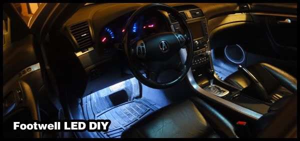
Why are LEDs so awesome?
Well, you can add them pretty much anywhere.
Your computer, your car, your desk, your house, etc.
Today, I'll be teaching you guys how to add them into your car's footwell area!
So how will they function?
I'll be wiring them to the dome supervisor wire, so that means whenever you open your door, they turn just like the domes do, and fade out just like the domes do.
When you're driving and someone turns on the domes, your footwells WILL NOT turn on.
Many cars have these already, and if you've always wanted to know how to add them, read on!
So what's so cool about this mod?
It's CHEAP. My LED strips cost me about 30 dollars, shipped right to Canada.
It would be cheaper for fellow Americans, obviously.
So what's needed?
The material list:
1. 4 LED Strips of your choice and colour - I bought 6" 5 LED white LED strips.
I didn't want mine too bright so that's why I bought 6" instead of 12".
If you think LED strips are overkill, use 2 LEDs if you want and solder them together (MORE WORK!).
2. T-Tap connectors or Splice Connectors.
I ended up using around 7 of them.
3. Primary wire aka "wire".
I recommend 18 gauge.
I ended up buying 2 spools.
4. Butt connectors.
I ended up using 8 of them.
You'll want to buy 18-22 gauge butt connectors.
5. Add-a-Fuse with 3A fuse.
5. Straightened clothes hanger
6. Electric Tape
7. Wire stripper + crimper
8. Mounting Tape
Okay so lets get started!
We'll be wiring everything first.
Then mount after.
Wiring:
1. Lay out your LED strips.
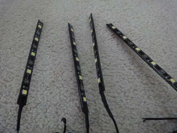
2. Each LED strip should have 2 wires coming out from it.
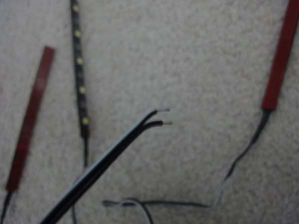
One wire is a positive wire, and one wire is a negative wire.
Red is usually positive and black is usually negative.
For me, the black and white stripe wire was positive and the black wire was negative.
3. Grab your stuff and head out to your car
4. Disconnect to negative terminal on your car.
Wiring your first LED strip:
I'll be starting on the driver side, and I assume you want to too!
Preparing the positive wire:
1. Grab your Add-A-Fuse and stick the 3A fuse in the slot for the accessory (our LEDs).
2. Slide open your driver fuse box cover, and look for the fuse that is labeled "Power Seat Slide".
I forgot what fuse # it is but it's the one in this picture:
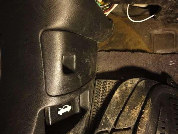
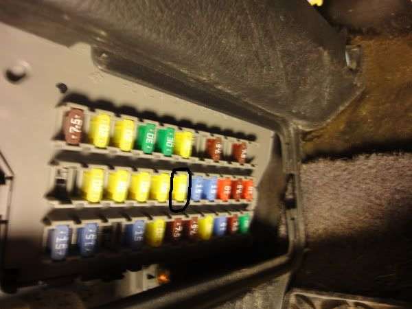
3. Pull that fuse out and put it in the slot for the Add-A-Fuse.
4. Take your primary wire and cut a foot of it.
5. Strip back one end, and crimp it down to the wire on the Add-A-Fuse.
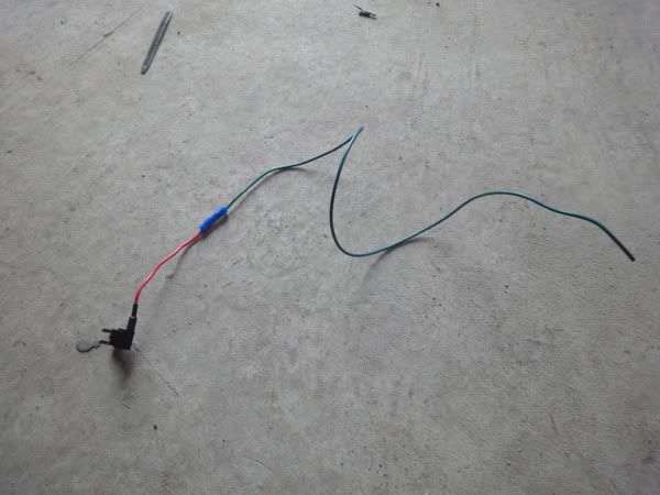
4. Now stick your add-a-fuse in that now empty "Power Seat Slide" fuse.
6. At the end of your primary wire that's attached to the add-a-fuse, strip it back, and use a butt connector to connect it to the positive wire (red wire, or black and white stripe in my case) on your LED strip.
7. Wiring your positive is now done! Easy? I love the Add-A-Fuse device lol.
To complete the wiring, we need to hook up the negative wire now:
1. Remove the lower dash panel.
There's just one screw you remove.
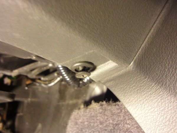
Then pull the panel which disengages the clips.
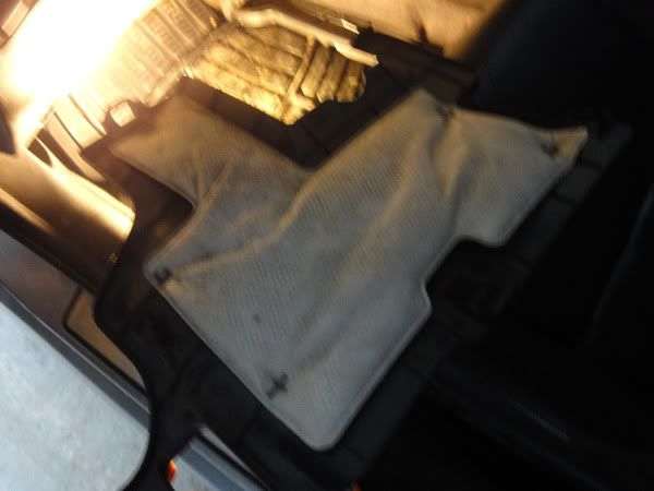
2. I ended up having to remove the lower dash panel, too.
All there is are clips, again.
3. We now have full access to the fuse box.
This is what you should see:
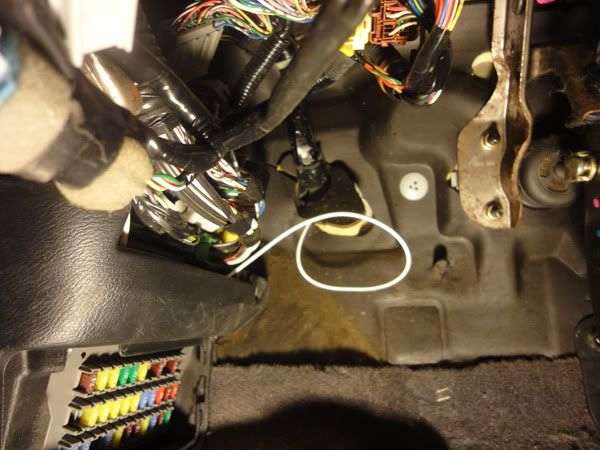
That white wire you don't have because it's for my accord fogs lol
4. Disconnect the 5-pin harness connector behind the fuse box.
The connector is located behind the turn signal relay at the very top right of behind the fuse box.
You can definitely feel it. You can feel each wire and count 5 of them if you want too lol
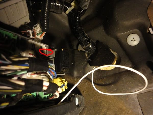
The tab is at the top and you push it down and pull out.
It was difficult for me, since it was behind the fuse box.
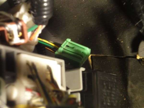
5. You should see a green with red stripe wire on that 5 pin connector.
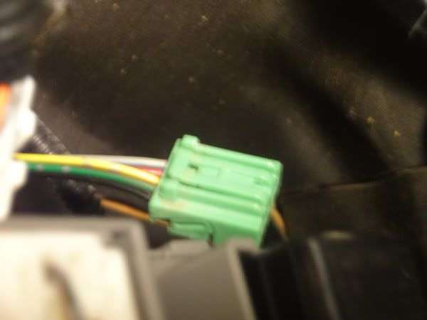
That's the dome super visor wire.
6. Cut a foot of wire using your primary wire.
You won't need to strip it if you're using "self-stripping" connectors.
7. With the foot of primary wire, tap into the dome supervisor wire with a splice connector or T-Tap connector.
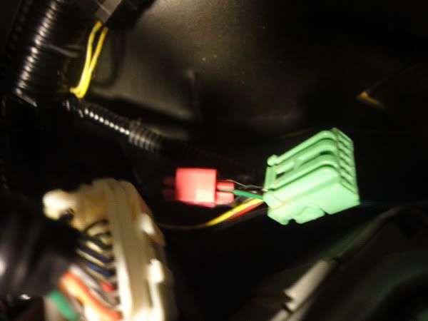
8. Now at the end of this primary wire, strip it back and use a butt connector to crimp it to the negative wire of your LED strip.
YAY ALL DONE!
You can now go and test it out!
Hook your negative terminal back in, and open the door.
If the LED strip turns on, you're ready to add the other LED strips!
If not, make sure your connections are making contact.
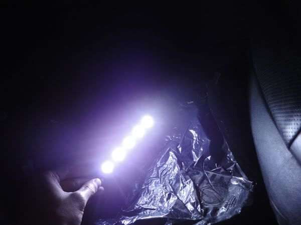
Here's what you your setup should look like:
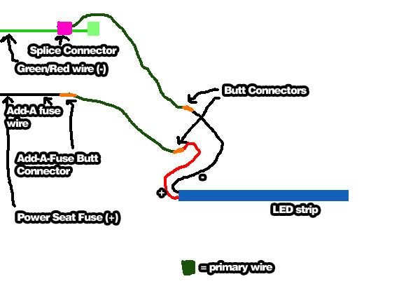
If it lights up, the HARDEST part is over!
Now all you have to do is tap the + and - wires from the other LED strips!
Lets move on to the passenger footwell!
1. Unplug your negative terminal on your battery if you havn't already.
2. Cut 2 wires that can reach from your driver footwell to your passenger side footwell.
I didn't measure. Maybe 4 feet each wire? IDK. Just make sure it spans enough to reach.
3. Get your straightened clothes hanger, and electric tape the two wires onto the end of the clothes hanger.
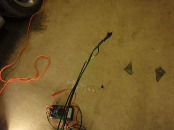
4. Using the provided "gap" behind the center console, push the clothes hanger GENTLY through so it comes through the other side.
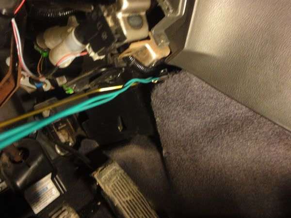
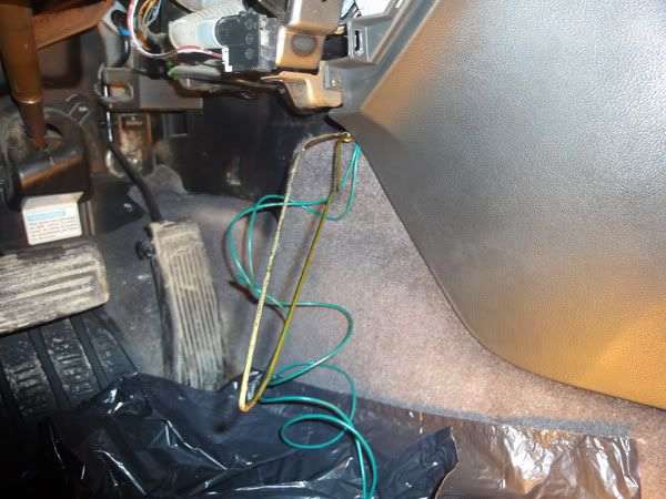
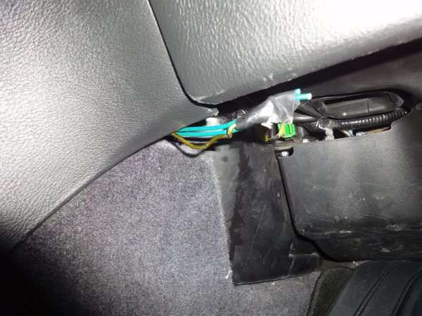
5. Remove the electric tape, and pull out the clothes hanger.
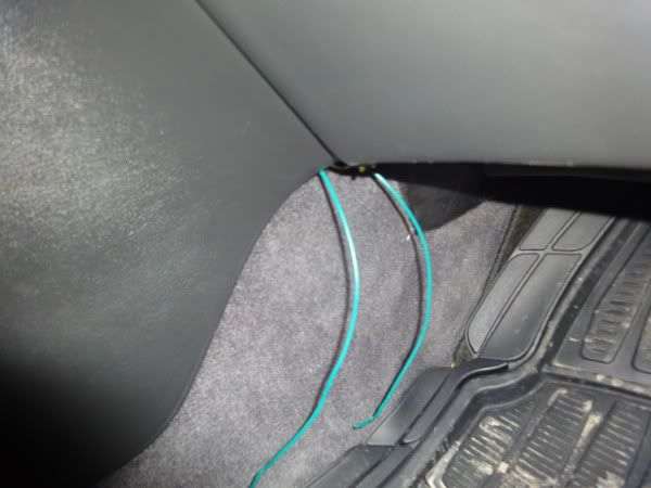
6. Wire one wire to the negative (black) of your LED strip using a butt connector.
7. Wire the other wire to the positive (red) of your LED strip using a butt connector.
8. Now head over to the driver side again, and see which one is the negative wire.
You can pull a wire from the passenger side and see which one moved.
Say you held onto the positive wire of the LED strip on the passenger side, and tugged it. The wire that moves on the driver side is your positive wire.
I think a little kid could figure it out LOL
Just don't wire your positive to negative haha
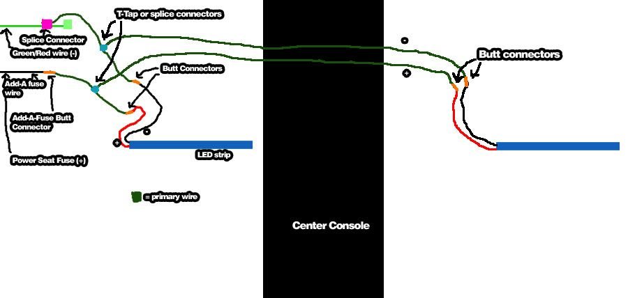
9. When you determine which wire is which, positive or negative, use a splice connector or T-Tap and tap it into its corresponding PRIMARY wire (don't tap into the LED strip wiring).
This is what you should have...
Test it out!
See if it lights up by plugging in the negative terminal and opening the doors.
If it works, time to do the rears!
Unplug the negative terminal again on your battery.
I did the driver rear first.
1. Cut two wires from your primary wire spool that can run from the fuse box to behind the driver seat.
Again, I didn't measure.
2. Connect one wire to the LED strip's positive using a butt connector
3. Connect the other wire to the LED strip's negative wire using the butt connector.
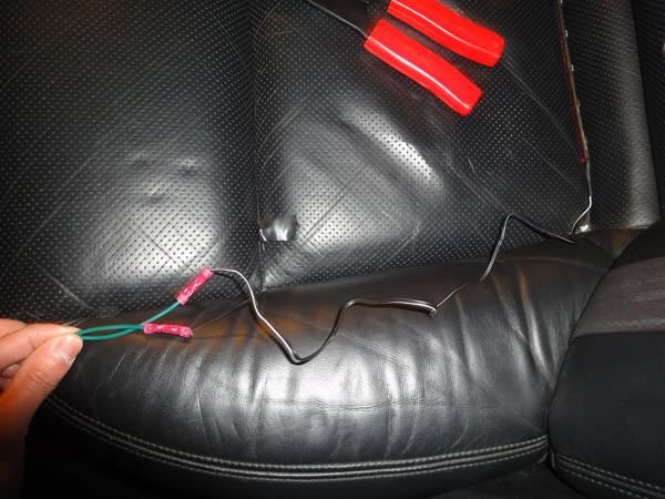
4. Feed the wire through under the seat mount/bracket.
5. Move up to the driver area now, and figure out which wire is positive and which is negative.
All similar to what we did for the passenger footwell:
6. Tap (using a splice connector or T-Tap) the rear's positive primary wire to the primary wire that's positive used to power the driver footwell.
7. Tap (using a splice connector or T-Tap) the rear's negative primary wire to the primary wire that's negative used to power the driver footwell.
You should have the same setup:
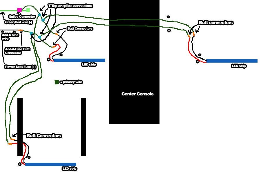
You can test it out if you want now.
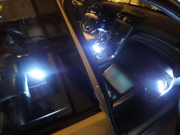
Now for the last footwell!
The rear passenger:
1. Unplug the negative terminal on your battery if you havn't already.
Same concept as the driver rear footwell, but this time you're tapping the wires to the passenger footwell's primary wire.
2. Cut two wires that can reach and span from your passenger footwell to behind the passenger seat.
3. Connect one of the wires to the positive wire on the LED strip using a butt connector.
4. Connect the other wire to the negative wire on the LED strip using a butt connector.
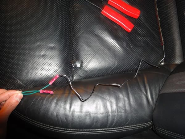
5. Route the wires under the passenger seat bracket and bring it all the way to the passenger area.
6. Now working in the passenger area, figure out which wire is positive and which wire is negative.
7. Using a T-Tap or splice connector, tap the rear's negative wire to the negative primary wire we fed behind the center console to power the passenger LED strip.
8. Using a T-Tap of splice connector, tap the rear's positive wire to the positive primary wire we fed behind the center console to power the passenger LED strip.
This is what you should have:
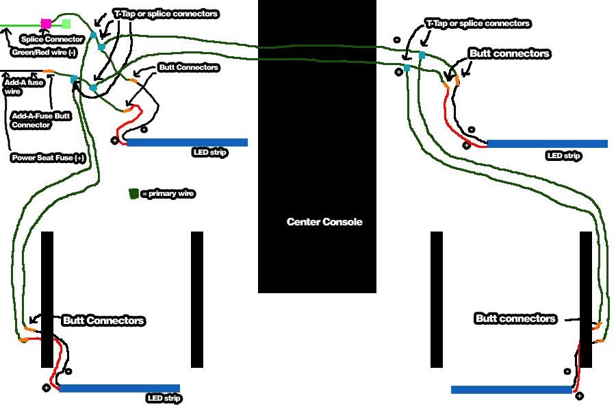
ALL DONE!
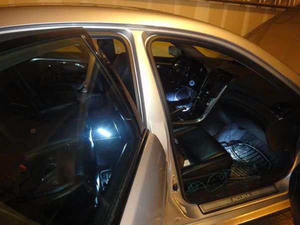
You can plug your negative battery terminal back in and test all the lights out!!
This is what you should have in your driver area:
2 primary wires to power the LED strip 1 (driver)
1 butt connector on the end of each primary wire to power LED strip 1
2 splice connectors or T-tap connectors on each primary wire, for the driver rear and passenger.
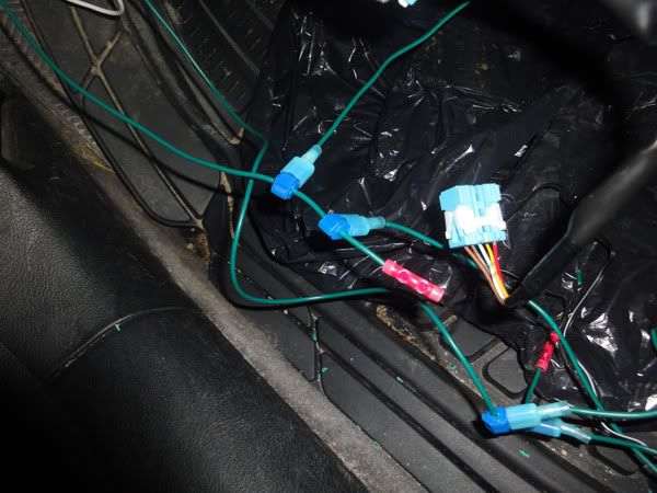
This is what you should have in your passenger area:
2 primary wires coming from the driver side to power the LED strip 2 (passenger)
1 butt connector on the end of each primary wire to power the LED strip 2.
1 splice connector or t-tap connector on each primary wire, to power the rear passenger LED strip.
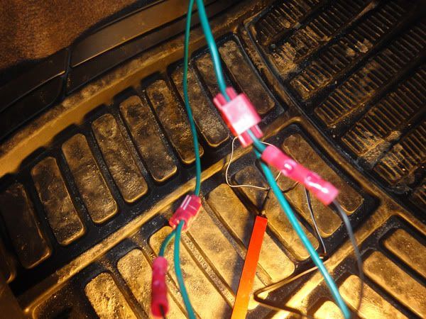
Cheers!
Mounting is coming up!
#203
Race Director
Thread Starter
iTrader: (8)
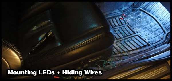
First stage is mounting the LED strips.
Second stage is hiding the wires.
Mounting the LED strips:
Driver side:
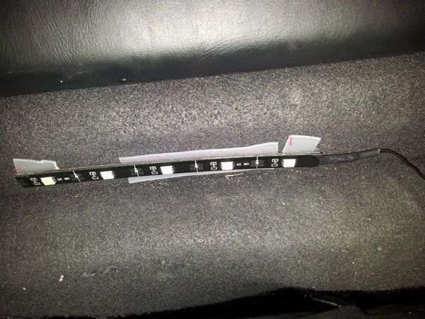
1. Take your mounting tape and stick it on the back side of your LED strip.
If your LED strip is preinstalled with an adhesive, remove the protective cover from this adhesive and stick the mounting tape onto the adhesive. OR just use the adhesive tape it came with and not use mounting tape at all.
2. Pick a spot, preferably where the light shines evenly down the center.
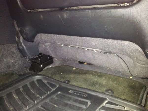
I mounted it to the lower dash cover, pretty much above the brake pedal.
3. Remove the mounting tape protective film and stick it on.
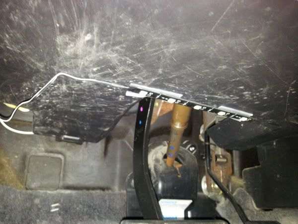
Easy.
Passenger side:
Do the same thing.
I mounted mine at the back on the lower dash cover, too.
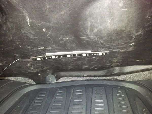
Rears:
Do the same thing.
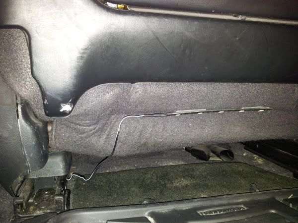
I mounted mine on the back portion of the front seats.
Hiding the wires:
Passenger side:
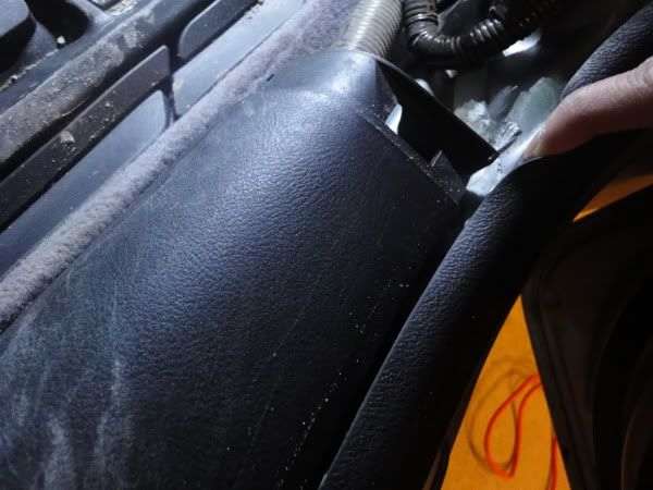
1. Remove the first trim cover.
It's just clips that hold it in.
2. Pull the lining that runs along the side channel out.
No tricks.
3. Remove the side trim.
There are just clips that hold it in. Start popping the clips from the front to the back.
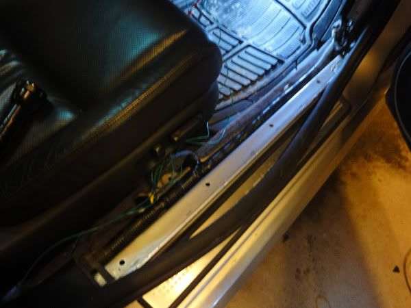
4. Run the primary wires beside the wire loom under the side panel.
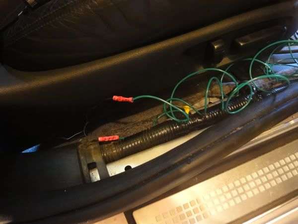
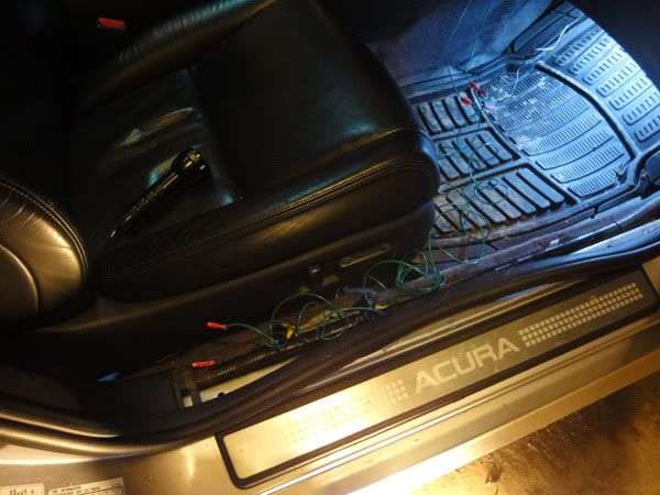
5. Put the side trim back on, covering the wires.
6. Push the lining back in.
7. Pull down the lower dash cover, bring all the wires up there to hide them.
Push the lower dash cover back up. All wires hidden.
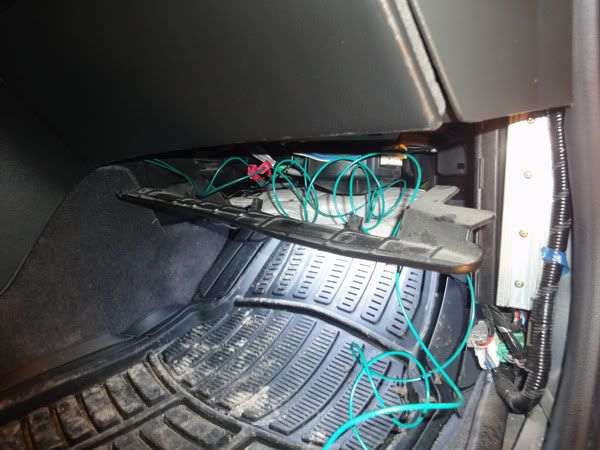
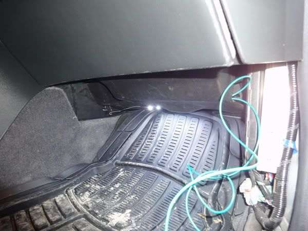
8. Finish it all off my putting the first trim cover back on.
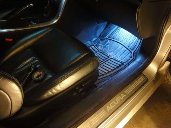
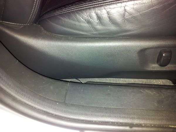
There you have it. No wires should be visible, except for the short amount of wire for the LED strips.
Driver side:
1. Remove fuse box trim
There are just clips holding it in.
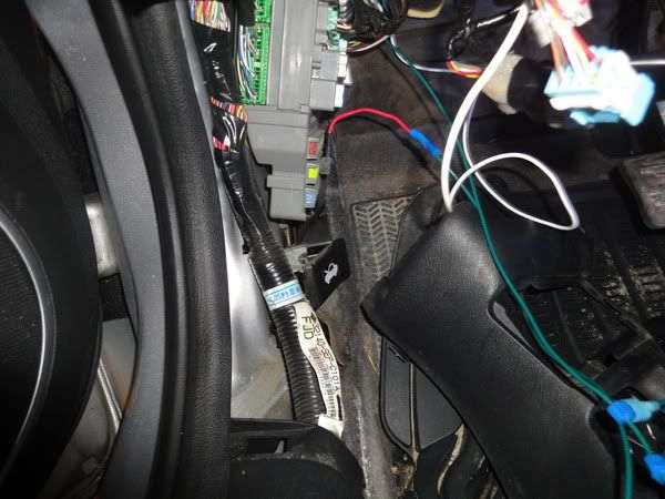
2. Peel back the lining just like you did on the other side
3. Remove the side trim, which are held in by clips.
Again, pop the clips working front to back.
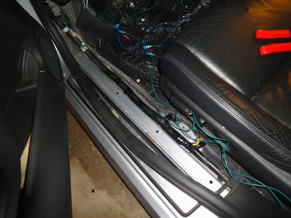
4. Run the primary wires along with the big wire loom.
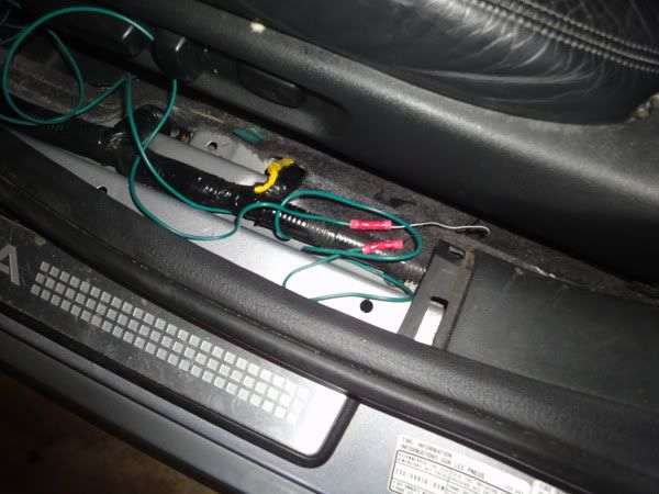
5. Place the side trim over all of it.
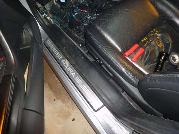
6. Push the lining back in.
7. Place fuse trim piece back in.
At this point, you can put back on the lower dash panel, BUT not the lower dash cover.
8. Just like we did on the passenger side, we're hiding all the wires and connections on top of the lower dash cover.
#204
Race Director
Thread Starter
iTrader: (8)
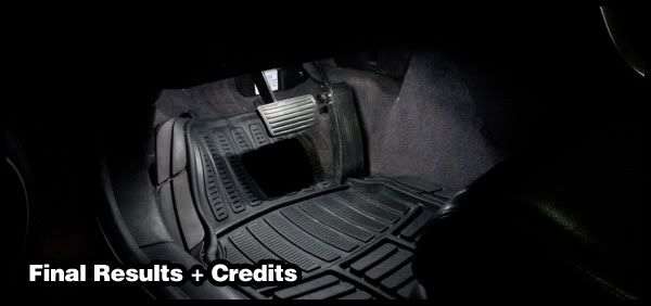
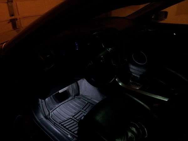
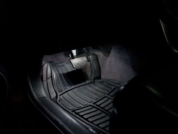
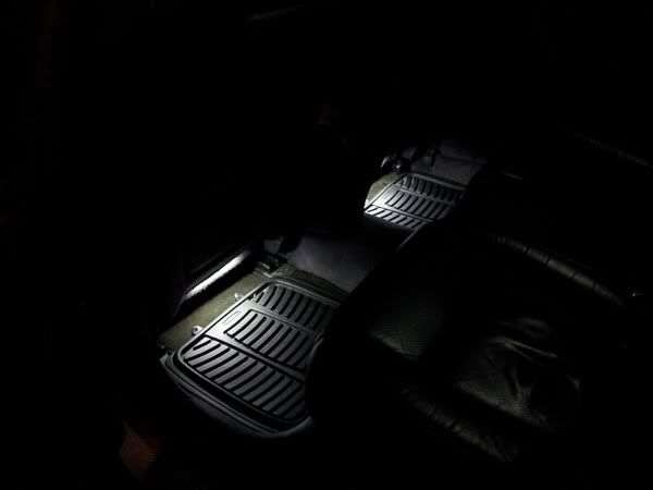
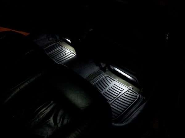
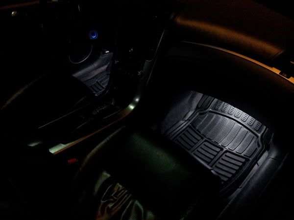
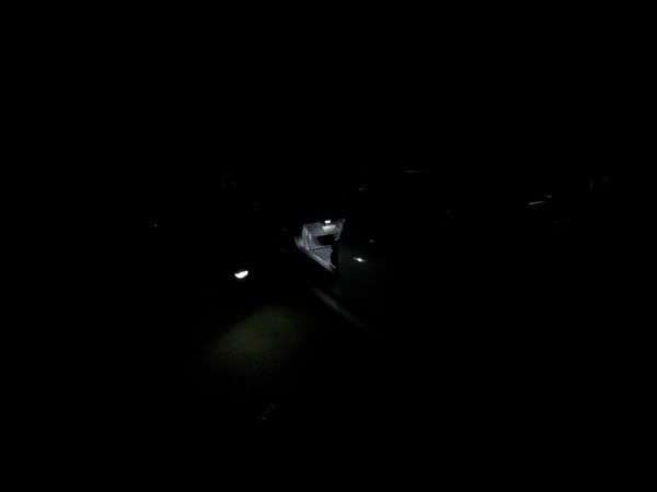
Special thanks to vladkarnafel, dwb993, swoosh, Rockstar143, SharksBreath, Roger555, vietxquangstah, GeeteeDan and others who have helped me make this DIY possible.
#205
Race Director
Thread Starter
iTrader: (8)
Fixed the photobucket images and have them uploaded on acurazine.
If a mod can edit the first post with the contents of the posts above that'd be greatly appreciated!
(Use "Source" of post above and copy to "Source" of original post)
After confirming that it show up right, please delete these recent posts (ONLY after confirming it shows right!)
Thanks!
GP16
If a mod can edit the first post with the contents of the posts above that'd be greatly appreciated!
(Use "Source" of post above and copy to "Source" of original post)
After confirming that it show up right, please delete these recent posts (ONLY after confirming it shows right!)
Thanks!
GP16
Thread
Thread Starter
Forum
Replies
Last Post
rockyboy
2G RDX (2013-2018)
171
08-04-2024 10:35 AM
rockyboy
2G RDX (2013-2018)
46
01-25-2016 06:00 PM
sockr1
Car Parts for Sale
22
10-01-2015 01:31 AM


