Supercharger Thoughts
 08-02-2003, 08:01 AM
#41
Three Wheelin'

Join Date: Feb 2003
Location: Grand Rapids, Michigan
Posts: 1,796
Likes: 0
Received 0 Likes
on
0 Posts
I'm going to spend some time today doing some tubing management. I'd like to bypass the TB coolant lines but when I had the LS1, I read that in northern climates, ice could form inside and freeze up the blade, possibly at WOT. Any thoughts on that?
 08-02-2003, 09:23 AM
#42
Suzuka Master
Thread Starter
Join Date: Sep 2000
Location: Woodstock, GA
Age: 53
Posts: 9,431
Likes: 0
Received 0 Likes
on
0 Posts
Originally posted by ModAddict
That would be great. I wonder if I'll need a VSA simm,....
That would be great. I wonder if I'll need a VSA simm,....
Or a two dollar relay could be used to simulate the signal back to the VSA control unit.
08-02-2003, 09:24 AM
#43
Suzuka Master
Thread Starter
Join Date: Sep 2000
Location: Woodstock, GA
Age: 53
Posts: 9,431
Likes: 0
Received 0 Likes
on
0 Posts
Originally posted by ModAddict
I'd like to bypass the TB coolant lines but when I had the LS1, I read that in northern climates, ice could form inside and freeze up the blade, possibly at WOT. Any thoughts on that?
I'd like to bypass the TB coolant lines but when I had the LS1, I read that in northern climates, ice could form inside and freeze up the blade, possibly at WOT. Any thoughts on that?
 08-02-2003, 09:35 AM
#44
Suzuka Master
Thread Starter
Join Date: Sep 2000
Location: Woodstock, GA
Age: 53
Posts: 9,431
Likes: 0
Received 0 Likes
on
0 Posts
The more and more I look under the hood I get worried about the room for the tube style IC. It can definitely be made to work with some fabrication and finagling. But the additional volume is what's worrying me. This increased volume and turns may hurt some, lessening the gains.
But we won't know until it is tried. I might pick up some 6 inch PVC and cut it to the various lengths to get a better feel for this.
But honestly, the dyno results concerning the IMRC valve may control my decision on the direction taken with the IC. If it is proven that the IMRC valve is worthless and should remain closed (or the center chamber blocked off) then replacement of the upper manifold would be ideal. I'm thinking on the lines of something looking similar to the stock manifold but with a large liquid/air IC in the middle. This would decrease the filling volume for the SC which will increase response and maybe performance slightly. And it could be made to enhance the flow properties for forced induction.
The large open area over the transmission behind the blower and intake could then be used for a decent sized reservoir with an opening for ice...
08-02-2003, 11:45 AM
#45
Three Wheelin'
Join Date: Feb 2003
Location: Grand Rapids, Michigan
Posts: 1,796
Likes: 0
Received 0 Likes
on
0 Posts
I've said before, I know there's room for improvement on the Intake manifold. I think the Accord intake has a cleaner pathway to the runners. An integral IC would be the best for sure. Is the top of the intake manifold sealed with a dry gasket? I would like to open it up but don't have a new gasket.
As far as the tube IC, there would be the added volume of the IC itself, a 3" 180 decgree elbow, and a 3" return pipe maybe 15"long. I think it will be easier to place the IC on top between the 180 turn and the intake elbow. There is more room diameter-wise, but less room length-wise. I thought I would put it on the bottom for the extra legth, but I think the diameter will collide with the cast intake elbow.
I'll be happy for now with the new pulley, and I won't have the two 90* elbows until mid August, but when the headers arrive, I may be off to the machine shop for some finagling. Relocating the MAP will be ok either way so I may go ahead and do that now. Cutting back the outlet neck will only need a longer connecter to put it back, but won't be done w/o the blower off. I guess I could get one from Comptech to cut,....maybee.
08-02-2003, 01:34 PM
#46
Suzuka Master
Thread Starter
Join Date: Sep 2000
Location: Woodstock, GA
Age: 53
Posts: 9,431
Likes: 0
Received 0 Likes
on
0 Posts
Originally posted by ModAddict
Is the top of the intake manifold sealed with a dry gasket? I would like to open it up but don't have a new gasket.
Is the top of the intake manifold sealed with a dry gasket? I would like to open it up but don't have a new gasket.
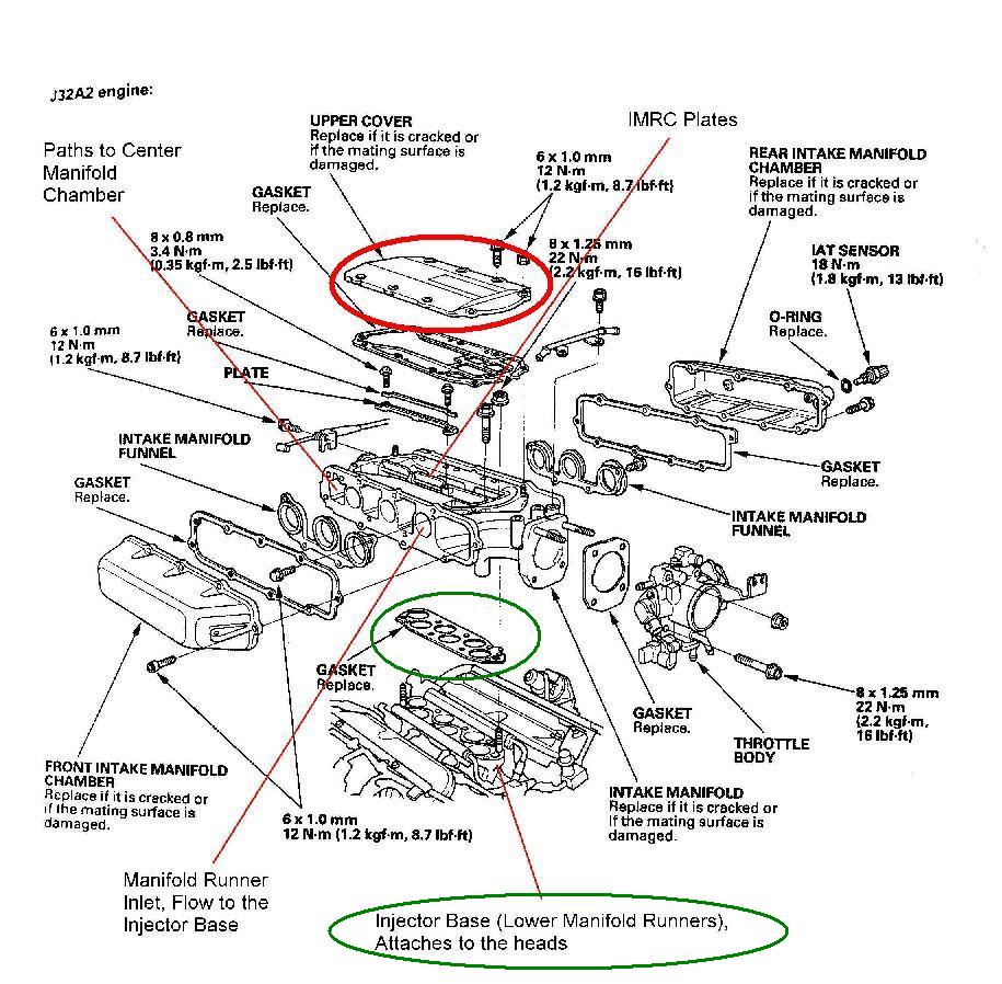
If you are talking about the gasket between the upper manifold and the injector base at the location shown below, it is also metal and could be reused.

Feel free to browse these directories instead of pulling parts to get a feel for the manifold:
Intake Manifold Polishing Directory
08-02-2003, 07:49 PM
#47
Suzuka Master
Thread Starter
Join Date: Sep 2000
Location: Woodstock, GA
Age: 53
Posts: 9,431
Likes: 0
Received 0 Likes
on
0 Posts
I went ahead and ran some numbers on a new intake manifold IC system and it looks very promising. Please excuse how rough the below sketch, and it is certainly not in scale. But it does represent the idea and one which would require minimal fabrication as all sections are squared.

In the above the Comptech SC would not be modified at all. The outlet pipe would be attached to. All factory vacuum ports would be retained along with sensor mounting excluding the MAP which would be put on the side of the inner chamber.
The center chamber would have access through a top cover similar to the stock set up. The major difference is the runner length which is shortened by about 30%. This might help top end power without sacrificing the low end since it would be under boost and come up quicker due to less total volume to fill.
The best part is the IC volume; this would be the equivalent to a 2000 square inch air/air unit. It should provide greater than 85% efficiency with little flow loss. In other words, at least a 10% gain in power over not having the unit.
08-03-2003, 06:27 AM
#50
Suzuka Master
Thread Starter
Join Date: Sep 2000
Location: Woodstock, GA
Age: 53
Posts: 9,431
Likes: 0
Received 0 Likes
on
0 Posts
I'll do up a better drawing later today/tonight and send it to Turbonetics for review. I'm not sure if we would have them do the whole thing or just the core. But I would prefer them to do the entire assembly.
http://www.turboneticsinc.com/liquid.html
That would be nice to receive a unit from them and have it bolted in place within an hour. It should look pretty clean and trick too. Not to mention a custom turbo set up could also use this.
I'll post the drawings when ready along with the email I send to them. I know Eric will want one too, how about Smitty?? If we can have five made or more, it should save some $$$ for each of us. Then maybe we should sell the design to Comptech�
08-03-2003, 06:32 AM
#51
Suzuka Master
Thread Starter
Join Date: Sep 2000
Location: Woodstock, GA
Age: 53
Posts: 9,431
Likes: 0
Received 0 Likes
on
0 Posts
BTW, I went out for a drive today with the IMRC Actuator connector pulled and there was no degradation in performance. In fact, it was more consistent in power all the way up to red line.
Someone else, who is boosted, try this out and report back. Just pull the electrical connector off the IMRC valve and see if there is any difference, good or bad.
Someone else, who is boosted, try this out and report back. Just pull the electrical connector off the IMRC valve and see if there is any difference, good or bad.
08-03-2003, 06:46 AM
#52
Suzuka Master

Join Date: Apr 2002
Location: Pittsburgh, PA
Age: 48
Posts: 9,940
Likes: 0
Received 0 Likes
on
0 Posts
Originally posted by scalbert
I know Eric will want one too, how about Smitty?? If we can have five made or more, it should save some $$$ for each of us. Then maybe we should sell the design to Comptech�
I know Eric will want one too, how about Smitty?? If we can have five made or more, it should save some $$$ for each of us. Then maybe we should sell the design to Comptech�
Are you crazy???.... you know the answer!!!... of course I am in..
Great idea Steve...
It looks like the Exhaust components are going to work out.. I will be sure to build a few O2 simulators so you BOOSTED guys can enjoy MORE HORSEPOWER without the Check engine light coming on.... but I am just in the testing phases.. I should have the pipes and everything within the next 2-3 weeks and a dyno to go with it!!!!!!..
Smitty
 08-03-2003, 07:35 AM
#54
Three Wheelin'
Join Date: Feb 2003
Location: Grand Rapids, Michigan
Posts: 1,796
Likes: 0
Received 0 Likes
on
0 Posts
Originally posted by scalbert
I'll do up a better drawing later today/tonight and send it to Turbonetics for review. I'm not sure if we would have them do the whole thing or just the core. But I would prefer them to do the entire assembly.
http://www.turboneticsinc.com/liquid.html
That would be nice to receive a unit from them and have it bolted in place within an hour. It should look pretty clean and trick too. Not to mention a custom turbo set up could also use this.
I'll post the drawings when ready along with the email I send to them. I know Eric will want one too, how about Smitty?? If we can have five made or more, it should save some $$$ for each of us. Then maybe we should sell the design to Comptech�
I'll see what's up with the "Max" boost pulley tomorrow. Won't your design fit on the CL-Ps and Accords too?
08-03-2003, 07:59 AM
#56
Suzuka Master
Thread Starter
Join Date: Sep 2000
Location: Woodstock, GA
Age: 53
Posts: 9,431
Likes: 0
Received 0 Likes
on
0 Posts
Originally posted by ModAddict
Won't your design fit on the CL-Ps and Accords too?
Won't your design fit on the CL-Ps and Accords too?
08-03-2003, 08:11 AM
#57
Three Wheelin'
Join Date: Feb 2003
Location: Grand Rapids, Michigan
Posts: 1,796
Likes: 0
Received 0 Likes
on
0 Posts
Originally posted by scalbert
You are probably correct. I would suspect that the injector base would be the same in all J series engines. That does expand the potential.
You are probably correct. I would suspect that the injector base would be the same in all J series engines. That does expand the potential.
 08-03-2003, 03:26 PM
#61
Three Wheelin'
Join Date: Feb 2003
Location: Grand Rapids, Michigan
Posts: 1,796
Likes: 0
Received 0 Likes
on
0 Posts
Steve, did you see this?
http://www.acura-cl.com/forums/showt...hreadid=109987
here's the jist of it
http://www.acura-cl.com/forums/showt...hreadid=109987
here's the jist of it
Originally posted by DeansblackCLS
ModAddict, My tech, Briant, along with Jason and myself have come up with a configuration that will fit everthing nicely. Looks like we are doing an aftercooler set up much like the ones on the Vortech kits with a resevoir, pump, aftercooler etc. We are waiting on pipes and the aftercooler to show up now and will begin mocking up shortly on a TL-S that we did a couple of weeks ago.
We finally got the pistons and the completed bottom end together for the 3.5 we have been working on since April--10 weeks for pistons! So, as soon as this thing is done and gone, we will begin on the Aftercooler set up.
Dean
08-03-2003, 03:28 PM
#62
Suzuka Master
Join Date: Apr 2002
Location: Pittsburgh, PA
Age: 48
Posts: 9,940
Likes: 0
Received 0 Likes
on
0 Posts
Makes total sense!!!

Brad thanks for clarifying that up.... Like you said "Steve is working on 1 end of the car and your working on the other!"..LOL... Hopefully my exhaust cut-out will even be more useful now...
Smitty
08-03-2003, 03:42 PM
#63
Three Wheelin'
Join Date: Feb 2003
Location: Grand Rapids, Michigan
Posts: 1,796
Likes: 0
Received 0 Likes
on
0 Posts
Re: Makes total sense!!!
Originally posted by Smitty
Brad thanks for clarifying that up.... Like you said "Steve is working on 1 end of the car and your working on the other!"..LOL... Hopefully my exhaust cut-out will even be more useful now...
Smitty
Brad thanks for clarifying that up.... Like you said "Steve is working on 1 end of the car and your working on the other!"..LOL... Hopefully my exhaust cut-out will even be more useful now...
Smitty
08-03-2003, 03:53 PM
#65
Suzuka Master
Join Date: Apr 2002
Location: Pittsburgh, PA
Age: 48
Posts: 9,940
Likes: 0
Received 0 Likes
on
0 Posts
Re: Re: Makes total sense!!!
Originally posted by ModAddict
No,no,...you're working on the other end with your exhaust project.
No,no,...you're working on the other end with your exhaust project.
Thats why I put it in "Quotation marks".... it came out of your mouth!!!... I just typed it out....LOL..
Smitty
08-03-2003, 04:25 PM
#66
Suzuka Master
Join Date: Apr 2002
Location: Pittsburgh, PA
Age: 48
Posts: 9,940
Likes: 0
Received 0 Likes
on
0 Posts
Originally posted by darrinb
wait so the 3.5 is finally coming out??
how much?
wait so the 3.5 is finally coming out??
how much?

For you guys who are pondering and scratching your heads.
This is what Steve and Modaddict are working on, Modaddict's theory before about intercooling the car is incorporated into Steves... Steve (Scalbert) wants to remove the Manifold and place a custom manifold on so that the air that comes in gets dumped right into the RUNNERS (those 6-circles in his pic), that is what it looks like when you remove the manifold.. A new custom manifold will be placed upon those runners and the stock will be put up on the shelf incase you ever want to return the car to stock.. The actuator will PROBABLY be removed..since you will want the Butterflies open all the time, not just during WOT..
Initially that air goes in the stock manifold and bounces around in there before going into the runner.. Steve wants the air to be cooled before it is Directly dumped into the new manifold which in turn goes right to the runners instead of bouncing around and the air will be cooled with H2O during summer and a mixture during the winter months.. Picture this...1 large cooler in the front of the rad and one small cooler before the throttle body.. the air will be cooler and pumped through using a small pump.. bring the air temperature down ..... as stated before in (theory) " 30-40 more horsepower"... depending on which boost pulley you are running...4.5 or 6 lbs of boost.... but it will increase HP without a doubt...I hope that helps...
Smitty
08-03-2003, 04:40 PM
#67
Three Wheelin'
Join Date: Feb 2003
Location: Grand Rapids, Michigan
Posts: 1,796
Likes: 0
Received 0 Likes
on
0 Posts
Re: Re: Re: Makes total sense!!!
Originally posted by Smitty
I know, I know
Thats why I put it in "Quotation marks".... it came out of your mouth!!!... I just typed it out....LOL..
Smitty
I know, I know
Thats why I put it in "Quotation marks".... it came out of your mouth!!!... I just typed it out....LOL..
Smitty
 08-03-2003, 04:49 PM
#68

--this is not a thread hijacking--
Smitty--I think that darrinb was talking about my post that Modaddict quoted up there.
We now return you to your regularly scheduled thread discussion of Steve's intake runner mod.
Smitty--I think that darrinb was talking about my post that Modaddict quoted up there.
We now return you to your regularly scheduled thread discussion of Steve's intake runner mod.
08-03-2003, 04:50 PM
#69
Suzuka Master
Thread Starter
Join Date: Sep 2000
Location: Woodstock, GA
Age: 53
Posts: 9,431
Likes: 0
Received 0 Likes
on
0 Posts
Originally posted by ModAddict
Wouldn't you want the butterflies open all the time rather than closed. Or better yet, like you said Steve, block off the plenum?
Wouldn't you want the butterflies open all the time rather than closed. Or better yet, like you said Steve, block off the plenum?
Watch your boost gauge; it will increase some at about 4k revs. When I removed the plates the boost was higher at the lower revs with nothing else changed. To me this indicates that something was obstructing airflow into the engine, be it turbulence or what. We all like boost but if the engine can use the same airflow with lower boost number you are making more power.
The more and more I think about this the better the new manifold sounds and make even help upper end power due to the changes in the runners. At least it is an interesting study.
08-03-2003, 04:51 PM
#70
Suzuka Master
Thread Starter
Join Date: Sep 2000
Location: Woodstock, GA
Age: 53
Posts: 9,431
Likes: 0
Received 0 Likes
on
0 Posts
Originally posted by DeansblackCLS
We now return you to your regularly scheduled thread discussion of Steve's intake runner mod.
We now return you to your regularly scheduled thread discussion of Steve's intake runner mod.
08-03-2003, 04:55 PM
#71
Suzuka Master
Thread Starter
Join Date: Sep 2000
Location: Woodstock, GA
Age: 53
Posts: 9,431
Likes: 0
Received 0 Likes
on
0 Posts
BTW, I just took off the TB and have it ready to be shipped overnight to King. I'll mic some measurements before I ship it so we will know exactly how much it is enlarged.
08-03-2003, 04:56 PM
#72
Three Wheelin'
Join Date: Feb 2003
Location: Grand Rapids, Michigan
Posts: 1,796
Likes: 0
Received 0 Likes
on
0 Posts
Originally posted by Smitty
For you guys who are pondering and scratching your heads.
This is what Steve and Modaddict are working on, Modaddict's theory before about intercooling the car is incorporated into Steves... Steve (Scalbert) wants to remove the Manifold and place a custom manifold on so that the air that comes in gets dumped right into the RUNNERS (those 6-circles in his pic), that is what it looks like when you remove the manifold.. A new custom manifold will be placed upon those runners and the stock will be put up on the shelf incase you ever want to return the car to stock.. The actuator will PROBABLY be removed..since you will want the Butterflies open all the time, not just during WOT..
Initially that air goes in the stock manifold and bounces around in there before going into the runner.. Steve wants the air to be cooled before it is Directly dumped into the new manifold which in turn goes right to the runners instead of bouncing around and the air will be cooled with H2O during summer and a mixture during the winter months.. Picture this...1 large cooler in the front of the rad and one small cooler before the throttle body..
the air will be cooler and pumped through using a small pump.. bring the air temperature down .....
as stated before in (theory) " 30-40 more horsepower"... depending on which boost pulley you are running...4.5 or 6 lbs of boost.... but it will increase HP without a doubt...I hope that helps...
Smitty
Smitty
08-03-2003, 05:01 PM
#73
scalbert,
No, we have not.
We are looking into having a separate aftercooler and running pipes from the S/C to it and back out to the throttlebody, but up in the engine bay and will it be water cooled.
No, we have not.
We are looking into having a separate aftercooler and running pipes from the S/C to it and back out to the throttlebody, but up in the engine bay and will it be water cooled.
08-03-2003, 05:13 PM
#74
Three Wheelin'
Join Date: Feb 2003
Location: Grand Rapids, Michigan
Posts: 1,796
Likes: 0
Received 0 Likes
on
0 Posts
Originally posted by scalbert
Nope, I found losses down low and unusual responses when I removed the IMRC plates.
Watch your boost gauge; it will increase some at about 4k revs. When I removed the plates the boost was higher at the lower revs with nothing else changed. To me this indicates that something was obstructing airflow into the engine, be it turbulence or what. We all like boost but if the engine can use the same airflow with lower boost number you are making more power.
The more and more I think about this the better the new manifold sounds and make even help upper end power due to the changes in the runners. At least it is an interesting study.
08-03-2003, 05:25 PM
#75
Suzuka Master
Thread Starter
Join Date: Sep 2000
Location: Woodstock, GA
Age: 53
Posts: 9,431
Likes: 0
Received 0 Likes
on
0 Posts
Originally posted by ModAddict
Ok, what about blocking off the plenum? It seams like that would clean up the flow.
Ok, what about blocking off the plenum? It seams like that would clean up the flow.
 08-03-2003, 06:50 PM
#77
Suzuka Master
Join Date: Apr 2002
Location: Pittsburgh, PA
Age: 48
Posts: 9,940
Likes: 0
Received 0 Likes
on
0 Posts
I am so excited, this is going to be such a BADASS mod... lets beat Batey to the table since he is doing the auto...LOL..
Smitty..
P.S. Talked with Jens tonight about the other end.. we got the ball rolling pretty good... tomorrow will tell the tale.
Smitty..
P.S. Talked with Jens tonight about the other end.. we got the ball rolling pretty good... tomorrow will tell the tale.
08-03-2003, 07:13 PM
#78
Suzuka Master
Thread Starter
Join Date: Sep 2000
Location: Woodstock, GA
Age: 53
Posts: 9,431
Likes: 0
Received 0 Likes
on
0 Posts
OK, I have the initial drawings done with a letter and zip file ready for Turbonetics. They don�t have an email address to send in information so I�ll call tomorrow to get one and talk to someone about this quickly.
I made a few small changes on the numbers for sizing but it turns our well. This intercooler should provide at least 85% efficiency. In other words, if the SC outlet temps are increased 100 F (which they are easily), the post IC temps are only 15 F over ambient. This is with minimal flow loss, maybe a half PSI boost lost.
Also, as a coincidence I ran the volume numbers on the new plenum and it comes up to almost 3.1 liters. This is ideal since you want just about the same size as you engine displacement.
I�ll keep ya�ll abreast as to Turbonetics response on this matter.
Below are the new drawings:
 08-03-2003, 07:21 PM
#80
Suzuka Master
Thread Starter
Join Date: Sep 2000
Location: Woodstock, GA
Age: 53
Posts: 9,431
Likes: 0
Received 0 Likes
on
0 Posts
Originally posted by Smitty
I am so excited, this is going to be such a BADASS mod... lets beat Batey to the table since he is doing the auto...LOL..
P.S. Talked with Jens tonight about the other end.. we got the ball rolling pretty good... tomorrow will tell the tale.
I am so excited, this is going to be such a BADASS mod... lets beat Batey to the table since he is doing the auto...LOL..
P.S. Talked with Jens tonight about the other end.. we got the ball rolling pretty good... tomorrow will tell the tale.
I'll have my bored out TB back by the end of the week to test out. The following weekend I'll try to head to the dyno to see what the numbers currently are. But I doubt I can make it that soon.
I would suspect that an initial IC/Manifold could be ready by the end of the month. What would be of great help is if someone could get to a dyno and run their car with and without the IMRC actuator connector plugged in. It may be several weeks before I can since the twins will be here no later than Wed. I would like to see this data before proceeding with the new manifold.
Dean's been a bit quite on this topic, are those Florida boys taking notes...