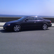
gauging interest...Led tailights

Thread Starter
Teh HORN!@!!!
Joined: Oct 2004
Posts: 796
Likes: 0
From: Chicago
haha, well the sooner i get the taillights the sooner itll happen, tricky part is gonna be matching the led's to the power that goes into the taillights. since the one circuit is a 3v power to have the lights on then a 12v hit when the brake pedal is pushed.
Plus does anybody have a hayes to gimme a wiring diagram so i dont fry out a few sets of leds testing sheit.
Plus does anybody have a hayes to gimme a wiring diagram so i dont fry out a few sets of leds testing sheit.


Pro
Joined: Apr 2005
Posts: 516
Likes: 0
From: SacTown, CA
Originally Posted by Nato
if you guys can actually make it look oem, count me in for sure.
looks hot
looks hot
 Make sure it looks like something from the factory and I'm in (depending on the price). I like the straight lines (i.e. 3G TL) better than the circles
Thread Starter
Teh HORN!@!!!
Joined: Oct 2004
Posts: 796
Likes: 0
From: Chicago
well im going to compare the zsize of leds, because i can do 2mm 5mm and 10mm leds...im gonna start with the 5mm and see how they sizez up and look. If to make it better ill goto 10mm and do more spaces.

how handsome I am
Joined: Oct 2004
Posts: 12,983
Likes: 1
From: Miami, FL
Originally Posted by Silentalero
well im going to compare the zsize of leds, because i can do 2mm 5mm and 10mm leds...im gonna start with the 5mm and see how they sizez up and look. If to make it better ill goto 10mm and do more spaces.




[QUOTE=Plus does anybody have a hayes to gimme a wiring diagram so i dont fry out a few sets of leds testing sheit.[/QUOTE]
I have the manual, but cant find it. I will take my voltage meter and go check them right now...
I have the manual, but cant find it. I will take my voltage meter and go check them right now...

So after some testing and retesting using 4 meters, and searching online, i have found after testing that there is no 3V source back there. It all goes from 11.somethin to 12.5ish. this was done with and without bulbes in... what i mean is that i peirced the wires and this is what t read on every wire that i got! be it break running, or turning! any ideas?

fear and Loathing
Joined: Jul 2005
Posts: 2,773
Likes: 0
From: Coventry, RI
Lets get these shits made, ooooo i can just see it now, i will have to trade cars with someone and follow them so i can see how pretty my car loos with the leds and my new HID's hehe i cant wait till spring time

Eurotrash


Joined: Apr 2002
Posts: 752
Likes: 44
From: Marin County, California
If an individual LED needs 3 volts, then put 4 LEDs in series, head to tail, so to speak. Now, this combination will run on 12 volts. Add more of this 4-LED combination in parallel with each other, and every LED will always see 3 volts.

Joined: Jan 2005
Posts: 92,780
Likes: 4,690
From: ShitsBurgh
Originally Posted by Tosh
If an individual LED needs 3 volts, then put 4 LEDs in series, head to tail, so to speak. Now, this combination will run on 12 volts. Add more of this 4-LED combination in parallel with each other, and every LED will always see 3 volts.


Eurotrash
Joined: Apr 2002
Posts: 752
Likes: 44
From: Marin County, California
Originally Posted by 97BlackAckCL
Just make sure to put a resistor in the series
I don't know what total resistance the burned-out-bulb-sensing-circuit needs (or if that's even the working principle), but perhaps this could be found by experimenting with some 5 watt resistors (not little 1/4 or 1/2W ones- they'll pop from the heat) in place of a bulb to check where the instrument warning lamp stops illuminating or blinker rate changes. The resistor values to start with would be found by just measuring the resistance of a dual filament bulb (across the brighter filament). But it's also possible that having a large number of LEDs (48? 96?) will satisfy the resistance requirement without adding resistors. Looking up the specs for the LED and a little calculation will yield that information.
Thread Starter
Teh HORN!@!!!
Joined: Oct 2004
Posts: 796
Likes: 0
From: Chicago
/\ thats exactly the formula i was going to work from because im going to make both sets of leds 1 circuit so i can use more to complete a larger number to avoid the resistor issue. If that doesnt work then what ill do is get 2 different series of leds and make one for brake lights full brightness, setup a relay and the other set work off the 3v operation

Nom Nom Nom Nom
Joined: Aug 2003
Posts: 11,801
Likes: 76
From: Universal City
Originally Posted by Silentalero
/\ thats exactly the formula i was going to work from because im going to make both sets of leds 1 circuit so i can use more to complete a larger number to avoid the resistor issue. If that doesnt work then what ill do is get 2 different series of leds and make one for brake lights full brightness, setup a relay and the other set work off the 3v operation
Thats exactly what i was thinking. Like put a row of leds, then every other one would be for brake lights. so it would look like x-x-x-x-x-x-x as standard then wen you hit the brakes it would be xxxxxxxxxxx


-S namyaC-
Joined: Sep 2003
Posts: 4,099
Likes: 0
From: TN
You guys are missing a bunch of the picture here. It's not really resistance the flasher is looking for, it's the load - IE current draw. You can use resistance to simulate that, but you need to calculate it from the current side. Do you guys know Ohm's Law? Do you know what the forward voltage drop of an LED means?
Kinda scares me you guys are willing to send $250 to a guy that doesn't even have a wiring diagram of the car (no offense dude).
Kinda scares me you guys are willing to send $250 to a guy that doesn't even have a wiring diagram of the car (no offense dude).
Eurotrash
Joined: Apr 2002
Posts: 752
Likes: 44
From: Marin County, California
If Proaudio is right (I think he is), then this would make for a simpler circuit overall, as there would be no need for any extra resistors.
I also get the feeling SilentAlero is on the wrong track by wondering about relays.
Also, it would be nicer (and probably cheaper overall) to use the same LEDs for brake lights and parking lights, that is two different voltages. That's the way most other cars are.
Sorry to put a damper on the fun, but this project needs a bit more brainstorming.
I also get the feeling SilentAlero is on the wrong track by wondering about relays.
Also, it would be nicer (and probably cheaper overall) to use the same LEDs for brake lights and parking lights, that is two different voltages. That's the way most other cars are.
Sorry to put a damper on the fun, but this project needs a bit more brainstorming.
Thread Starter
Teh HORN!@!!!
Joined: Oct 2004
Posts: 796
Likes: 0
From: Chicago
well see heres the thing, yes i know ohms law. im just looking at different aspects to do this. most likely im going to pull a wiring diagram from a G35 since they have a true led setup. then go from there. And no offense taken, if for any reason the circuitry doesnt work its not like im going to run with the cash. I wont ship any orders untill these are working perfect. But you also have to remember Nissan/Infinity has alot more resources to create a board to simply slide into a taillight. As to where i have to make the lights work bulb by bulb.
and yea i dont have the wiring diagram because first i need to see the taillights on the inside to even see how many and where i can position them before im concerned about what wire goes where. Plus the fact that I work 2 jobs doesnt give me much time. Im doing this because I saw some interest and i can work on it for a side project
and yea i dont have the wiring diagram because first i need to see the taillights on the inside to even see how many and where i can position them before im concerned about what wire goes where. Plus the fact that I work 2 jobs doesnt give me much time. Im doing this because I saw some interest and i can work on it for a side project
Burning Brakes
Joined: Aug 2003
Posts: 1,125
Likes: 0
From: Toronto
this isnt a new mod it has been done on many other cars like accords, civics, maximas ... i've seen it on other forums and they teach you how to do it...
on v6p.net couple of members have it.. you can check it out on their 6th gen accords
my buddy just got his done i'll take some pics of his tails he has a 6th gen coupe
on v6p.net couple of members have it.. you can check it out on their 6th gen accords
my buddy just got his done i'll take some pics of his tails he has a 6th gen coupe
say: zouts
Joined: Dec 2005
Posts: 646
Likes: 0
From: 33055 Miami, FL
this kind of mod should be very simple from the electrical standpoint, the voltage can be supplied by the leds in series, whereas if you need more current draw for sensor issues, you put a wirewound resistor in parallel with the entire led layout, so that the voltage remains the same for the leds... as far as using extra leds for braking, this shouldnt take more than a few transistors... at most 1 ic if necessary, but i wouldnt think so. a voltage sensing circuit like that could also be used to dim/brighten the leds, but thats up to you.
an entirely different story is how youre gunna get the leds inside the tail and lay them out properly.
an entirely different story is how youre gunna get the leds inside the tail and lay them out properly.

O.G.
Joined: Mar 2004
Posts: 1,181
Likes: 1
From: Northern Cali
Originally Posted by zhouz
this kind of mod should be very simple from the electrical standpoint, the voltage can be supplied by the leds in series, whereas if you need more current draw for sensor issues, you put a wirewound resistor in parallel with the entire led layout, so that the voltage remains the same for the leds... as far as using extra leds for braking, this shouldnt take more than a few transistors... at most 1 ic if necessary, but i wouldnt think so. a voltage sensing circuit like that could also be used to dim/brighten the leds, but thats up to you.
an entirely different story is how youre gunna get the leds inside the tail and lay them out properly.
an entirely different story is how youre gunna get the leds inside the tail and lay them out properly.
 wanna make us a diagram
  for people like me who are led illeterate. thanks
O.G.
Joined: Mar 2004
Posts: 1,181
Likes: 1
From: Northern Cali
heres some helpful info for led's
http://www.theledlight.com/ledcircuits.html
http://www.theledlight.com/ledcircuits.html

Thread Starter
Teh HORN!@!!!
Joined: Oct 2004
Posts: 796
Likes: 0
From: Chicago
Well just need a donor set still. Thats why i want a donor set before i worry about the electrical. I wanna get the layout first because doing the wiring is easy. The bulb size, fitting them and finding out how big of leds i actually need ois first priority.
and btw i can sell a spare center led bar with to if anybody wants that option.
and btw i can sell a spare center led bar with to if anybody wants that option.

Pro
Joined: Jan 2001
Posts: 598
Likes: 1
From: CA/FL
I've got a donor set I can lend you and you can take as much time as you need with them. Not in a rush to get them back seeing as both of my 1st gens are motor less awaiting new heart transplants. Let me know..