
G-100: DIY LED Interior Part VI: Front Passenger Door w/ RL Door-Handle LED!
 11-01-2009, 08:42 PM
#1
Fearless DIY Guy
Thread Starter
iTrader: (2)
G-100: DIY LED Interior Part VI: Front Passenger Door w/ RL Door-Handle LED!
Alright, trucking right along bring us to the sixth portion of the install, and this, in all actuality, is pretty simple and straightforward. Today, however, we will encounter a new challenge, also known as the PLCC-2 style LED. She's a temperamental one, and does not care for hot conditions. We're going to have to come back to this at a later point in time, I'll detail what is meant by this later on. Let's roll!!!
Thanks go to dwb993 for specifying the exact bulbs to use.
LET'S GO!
TOOLS NEEDED
Flat head screwdriver
Dremel w/ cutting wheel
Soldering Iron
MATERIALS
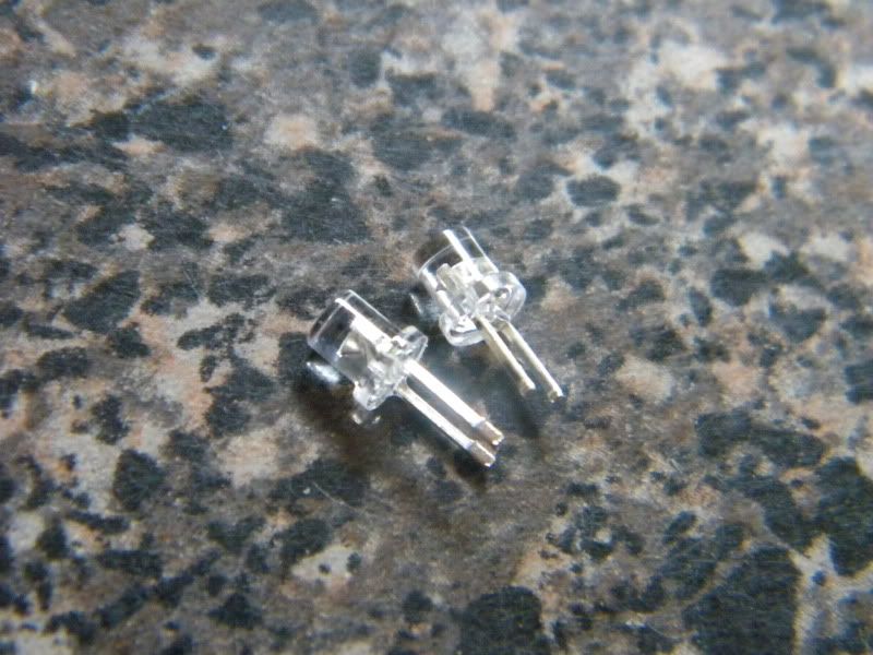
2 x 3mm bulb to your liking...I am used wide-angle flat headed 3mm bulbs
1 x PLCC-2 style LED bulb
Solder
FLUX, I CANNOT STRESS THIS ENOUGH
TIME
Plug-and-play method - 90minutes
STEP I - GETTIN' TO THE GOOD STUFF
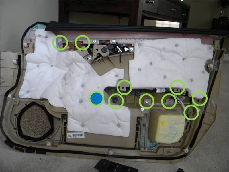
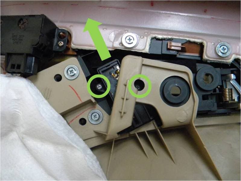
Ok, we'll start off by popping off zee OE paneling and pulling the necessary circuits. I have highlighted the screws that need to be removed in order to get those buggers out.
STEP II - ALL THUMBS
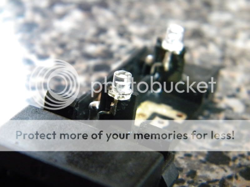
We're going to start with the lock switch, piece of cake. You can pop the cover off with your thumbs, it's quite simple. SO, what have we here? Ah, yes, I spy, with my little eye, two 3mm LEDs that don't quite fit the color code of our little club, so I will have to play the role of bouncer and evict them post haste...only thing is, in this club, violation of the rules are punishable by Dremel beheading.
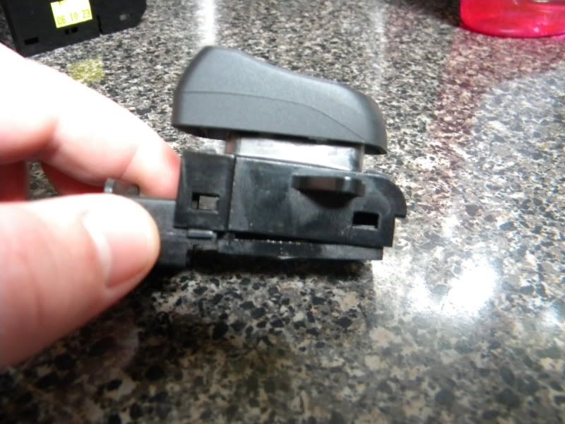
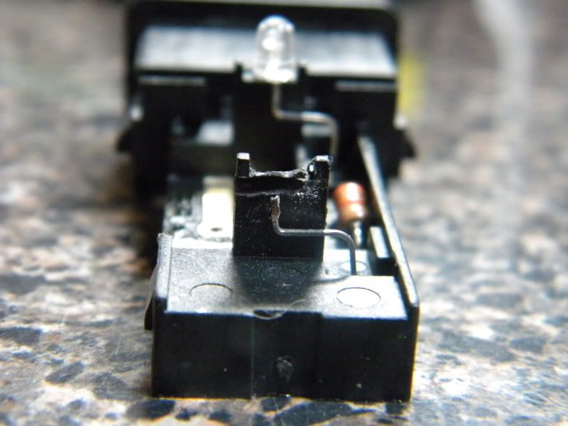
Snip the LEDs and solder in to position. Simple.
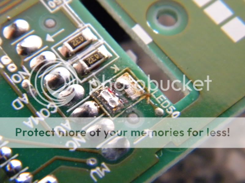
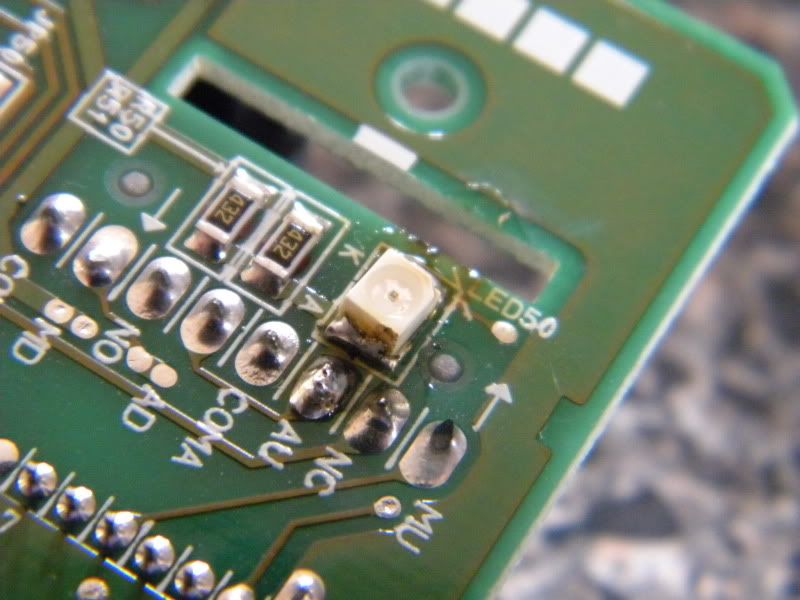
STEP III - A CHALLENGER APPROACHES!
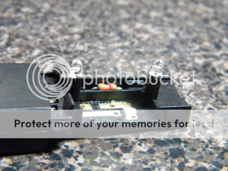
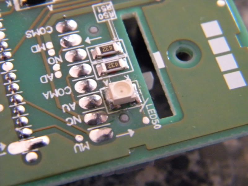
Window switch time. HO, HO, HO, WHAT HAVE WE HERE???? Ah, the PLCC-2 style LED. No fears, though! Ok, so, we're going to apply copper braid to the solder connections to adsorb the flux, then pop a new one in. NOW, make sure you pay attention to the location of the cathode end! It will be the side with the little corner notation. It will face the upper left hand side on the board. PROTIP: You don't have to replace the PLCC-2 with a PLCC-2, you can use a 3mm LED instead, but I will leave that choice up to you.
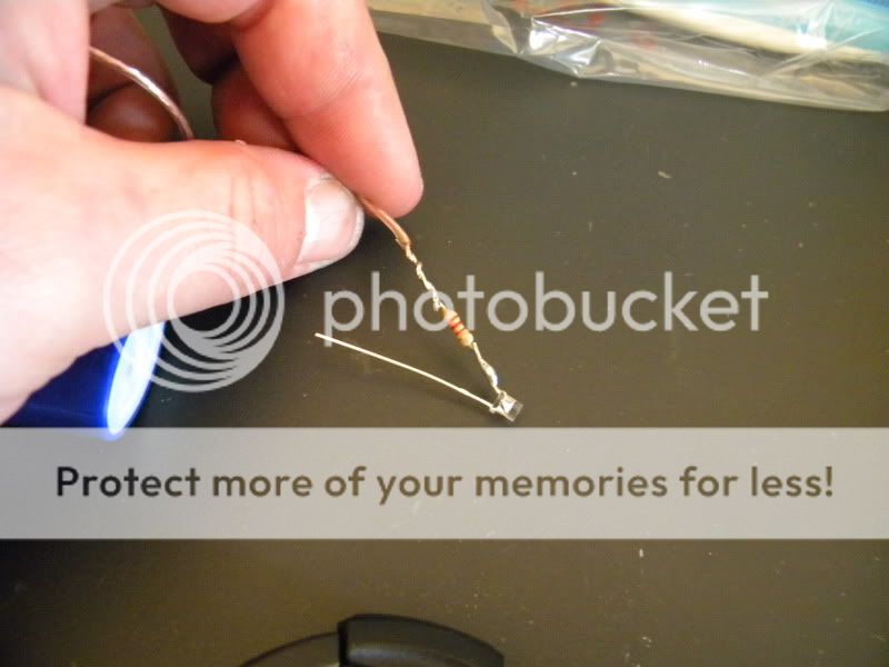
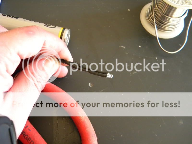
STEP IV - RL, TL, LED-L
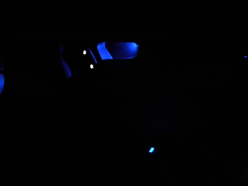
During my test drives of the TL and RL, I really did appreciate the blue backlight of the door handle, so I thought, "Why let them have all the fun?" So, what we're going to do is rain on their parade and have the same. Prepare an LED by attaching the 2.2k-ohm resistor to the cathode end, solder, shrink, and tape. We're using 2.2k-ohm because we want this to be SUBTLE. You're going to wire the negative to BLACK and the positive to the GREEN wire with a WHITE stripe that features the double-band of SILVER.

STEP V - AHHHHHHH
Ok, we're all done!
...sort of. Check out Part VII of the installment to see why.
Thanks go to dwb993 for specifying the exact bulbs to use.
LET'S GO!
TOOLS NEEDED
Flat head screwdriver
Dremel w/ cutting wheel
Soldering Iron
MATERIALS
2 x 3mm bulb to your liking...I am used wide-angle flat headed 3mm bulbs
1 x PLCC-2 style LED bulb
Solder
FLUX, I CANNOT STRESS THIS ENOUGH
TIME
Plug-and-play method - 90minutes
STEP I - GETTIN' TO THE GOOD STUFF
Ok, we'll start off by popping off zee OE paneling and pulling the necessary circuits. I have highlighted the screws that need to be removed in order to get those buggers out.
STEP II - ALL THUMBS
We're going to start with the lock switch, piece of cake. You can pop the cover off with your thumbs, it's quite simple. SO, what have we here? Ah, yes, I spy, with my little eye, two 3mm LEDs that don't quite fit the color code of our little club, so I will have to play the role of bouncer and evict them post haste...only thing is, in this club, violation of the rules are punishable by Dremel beheading.
Snip the LEDs and solder in to position. Simple.
STEP III - A CHALLENGER APPROACHES!
Window switch time. HO, HO, HO, WHAT HAVE WE HERE???? Ah, the PLCC-2 style LED. No fears, though! Ok, so, we're going to apply copper braid to the solder connections to adsorb the flux, then pop a new one in. NOW, make sure you pay attention to the location of the cathode end! It will be the side with the little corner notation. It will face the upper left hand side on the board. PROTIP: You don't have to replace the PLCC-2 with a PLCC-2, you can use a 3mm LED instead, but I will leave that choice up to you.
STEP IV - RL, TL, LED-L
During my test drives of the TL and RL, I really did appreciate the blue backlight of the door handle, so I thought, "Why let them have all the fun?" So, what we're going to do is rain on their parade and have the same. Prepare an LED by attaching the 2.2k-ohm resistor to the cathode end, solder, shrink, and tape. We're using 2.2k-ohm because we want this to be SUBTLE. You're going to wire the negative to BLACK and the positive to the GREEN wire with a WHITE stripe that features the double-band of SILVER.
STEP V - AHHHHHHH
Ok, we're all done!
...sort of. Check out Part VII of the installment to see why.

The following users liked this post:
perilousp (11-09-2012)
01-23-2010, 03:50 PM
#3
Mistuh DRiiVA
seriously its really not that hard and really worth it. I did my door buttons White instead of blue because my footwell lighting is BLUE and it offsets the color really nice.This mod on all 4 doors really made the doors look alot more appealing at night.
01-23-2010, 11:42 PM
#4
Fearless DIY Guy
Thread Starter
iTrader: (2)
UPDATE: NOTE FOR THOSE USING WHITE LEDS
I hate to bump all of the threads, but there is an important item that needs to be noted; some of the white LEDs have been burning out, which can be attributed to one thing and one thing only: thermal overload. Therefore,
IT IS HIGHLY RECOMMENDED THAT A 1K-OHM RESISTOR BE USED FOR ALL WHITE LEDS.
I have begun the process of replacing LEDs/resistors for the dearly-departed and can state that the new resistors seem to do the trick.
11-09-2012, 02:15 AM
#5

if i wanted the light to be really subtle,
(i.e. if it's bright enough to see the handle, i can't see or at least notice the handle light)
what ohm resistor should i use??
(i.e. if it's bright enough to see the handle, i can't see or at least notice the handle light)
what ohm resistor should i use??
11-09-2012, 04:46 PM
#7

think oem used 3.3k ohm, so i would think 2.2k - 3.3k would be good.
Trending Topics
11-10-2012, 03:24 PM
#8
Fearless DIY Guy
Thread Starter
iTrader: (2)
SO, can it be done? YES. Is it some serious work? Oh, yeah.
01-17-2019, 12:53 AM
#9
1st Gear

Join Date: Jan 2019
Age: 28
Posts: 1
Likes: 0
Received 0 Likes
on
0 Posts
Alright, trucking right along bring us to the sixth portion of the install, and this, in all actuality, is pretty simple and straightforward. Today, however, we will encounter a new challenge, also known as the PLCC-2 style LED. She's a temperamental one, and does not care for hot conditions. We're going to have to come back to this at a later point in time, I'll detail what is meant by this later on. Let's roll!!!
Thanks go to dwb993 for specifying the exact bulbs to use.
LET'S GO!
TOOLS NEEDED
Flat head screwdriver
Dremel w/ cutting wheel
Soldering Iron
MATERIALS
2 x 3mm bulb to your liking...I am used wide-angle flat headed 3mm bulbs
1 x PLCC-2 style LED bulb
Solder
FLUX, I CANNOT STRESS THIS ENOUGH
TIME
Plug-and-play method - 90minutes
STEP I - GETTIN' TO THE GOOD STUFF
Ok, we'll start off by popping off zee OE paneling and pulling the necessary circuits. I have highlighted the screws that need to be removed in order to get those buggers out.


STEP II - ALL THUMBS
We're going to start with the lock switch, piece of cake. You can pop the cover off with your thumbs, it's quite simple. SO, what have we here? Ah, yes, I spy, with my little eye, two 3mm LEDs that don't quite fit the color code of our little club, so I will have to play the role of bouncer and evict them post haste...only thing is, in this club, violation of the rules are punishable by Dremel beheading.


Snip the LEDs and solder in to position. Simple.


STEP III - A CHALLENGER APPROACHES!
Window switch time. HO, HO, HO, WHAT HAVE WE HERE???? Ah, the PLCC-2 style LED. No fears, though! Ok, so, we're going to apply copper braid to the solder connections to adsorb the flux, then pop a new one in. NOW, make sure you pay attention to the location of the cathode end! It will be the side with the little corner notation. It will face the upper left hand side on the board. PROTIP: You don't have to replace the PLCC-2 with a PLCC-2, you can use a 3mm LED instead, but I will leave that choice up to you.


STEP IV - RL, TL, LED-L
During my test drives of the TL and RL, I really did appreciate the blue backlight of the door handle, so I thought, "Why let them have all the fun?" So, what we're going to do is rain on their parade and have the same. Prepare an LED by attaching the 2.2k-ohm resistor to the cathode end, solder, shrink, and tape. We're using 2.2k-ohm because we want this to be SUBTLE. You're going to wire the negative to BLACK and the positive to the GREEN wire with a WHITE stripe that features the double-band of SILVER.


STEP V - AHHHHHHH
Ok, we're all done!
...sort of. Check out Part VII of the installment to see why.

Thanks go to dwb993 for specifying the exact bulbs to use.
LET'S GO!
TOOLS NEEDED
Flat head screwdriver
Dremel w/ cutting wheel
Soldering Iron
MATERIALS
2 x 3mm bulb to your liking...I am used wide-angle flat headed 3mm bulbs
1 x PLCC-2 style LED bulb
Solder
FLUX, I CANNOT STRESS THIS ENOUGH
TIME
Plug-and-play method - 90minutes
STEP I - GETTIN' TO THE GOOD STUFF
Ok, we'll start off by popping off zee OE paneling and pulling the necessary circuits. I have highlighted the screws that need to be removed in order to get those buggers out.
STEP II - ALL THUMBS
We're going to start with the lock switch, piece of cake. You can pop the cover off with your thumbs, it's quite simple. SO, what have we here? Ah, yes, I spy, with my little eye, two 3mm LEDs that don't quite fit the color code of our little club, so I will have to play the role of bouncer and evict them post haste...only thing is, in this club, violation of the rules are punishable by Dremel beheading.
Snip the LEDs and solder in to position. Simple.
STEP III - A CHALLENGER APPROACHES!
Window switch time. HO, HO, HO, WHAT HAVE WE HERE???? Ah, the PLCC-2 style LED. No fears, though! Ok, so, we're going to apply copper braid to the solder connections to adsorb the flux, then pop a new one in. NOW, make sure you pay attention to the location of the cathode end! It will be the side with the little corner notation. It will face the upper left hand side on the board. PROTIP: You don't have to replace the PLCC-2 with a PLCC-2, you can use a 3mm LED instead, but I will leave that choice up to you.
STEP IV - RL, TL, LED-L
During my test drives of the TL and RL, I really did appreciate the blue backlight of the door handle, so I thought, "Why let them have all the fun?" So, what we're going to do is rain on their parade and have the same. Prepare an LED by attaching the 2.2k-ohm resistor to the cathode end, solder, shrink, and tape. We're using 2.2k-ohm because we want this to be SUBTLE. You're going to wire the negative to BLACK and the positive to the GREEN wire with a WHITE stripe that features the double-band of SILVER.
STEP V - AHHHHHHH
Ok, we're all done!
...sort of. Check out Part VII of the installment to see why.

Thread
Thread Starter
Forum
Replies
Last Post
handsom-hustla
Car Parts for Sale
70
11-13-2015 05:04 PM
asahrts
Member Cars for Sale
0
09-04-2015 05:55 PM