
G-100: DIY LED Interior Part IX: Heated Seat Switches
 12-06-2009, 09:55 PM
#1
Fearless DIY Guy
Thread Starter
iTrader: (2)
G-100: DIY LED Interior Part IX: Heated Seat Switches
Alright, time to carry on the project. With an open weekend (for once, I elected to conquer the next step of the install, and that's the heated seat lights. I thought this would be simple, but of course, I was wrong. Let's get in to it.
Thanks go to dwb993 for specifying the exact bulbs to use.
LET'S GO!
TOOLS NEEDED
Flat head screwdriver
Soldering Iron
MATERIALS
6 x 3mm bulb to your liking...I am used wide-angle flat headed 3mm bulbs
Solder
FLUX, I CANNOT STRESS THIS ENOUGH
TIME
About 1 hours per switch, not counting the time it took to get to it.
STEP I - GETTIN' TO THE GOOD STUFF
Well, there's a little bit of work involved, but it's not too bad as only 4 screws need to be taken out as well as the console. CLICK HERE FOR THE THREAD. It's not hard. For cereal.
STEP II � MIL SPEC VS. WTF
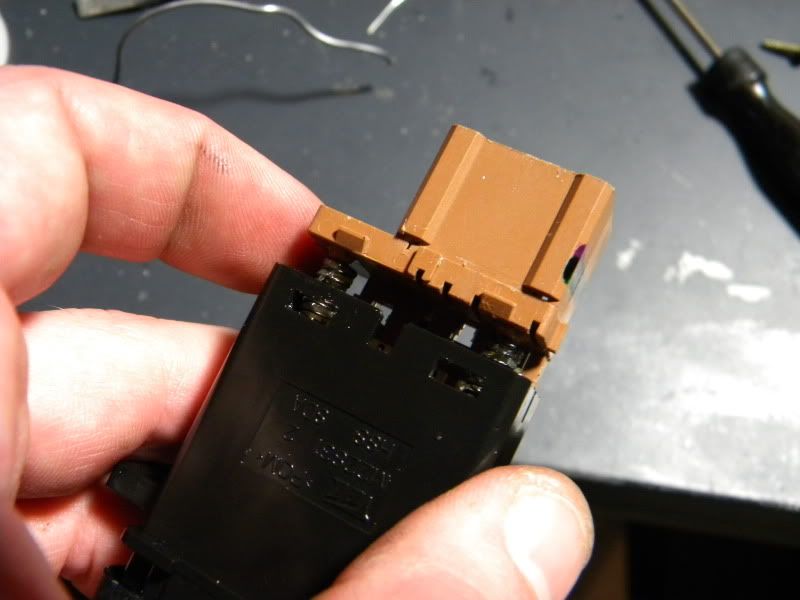
Now, popping out the main illumination button is quite easy...but the indicator lights? EHHHHH, not so much. Take out the first light...then use some flat-headed screwdrivers to pop the button open.
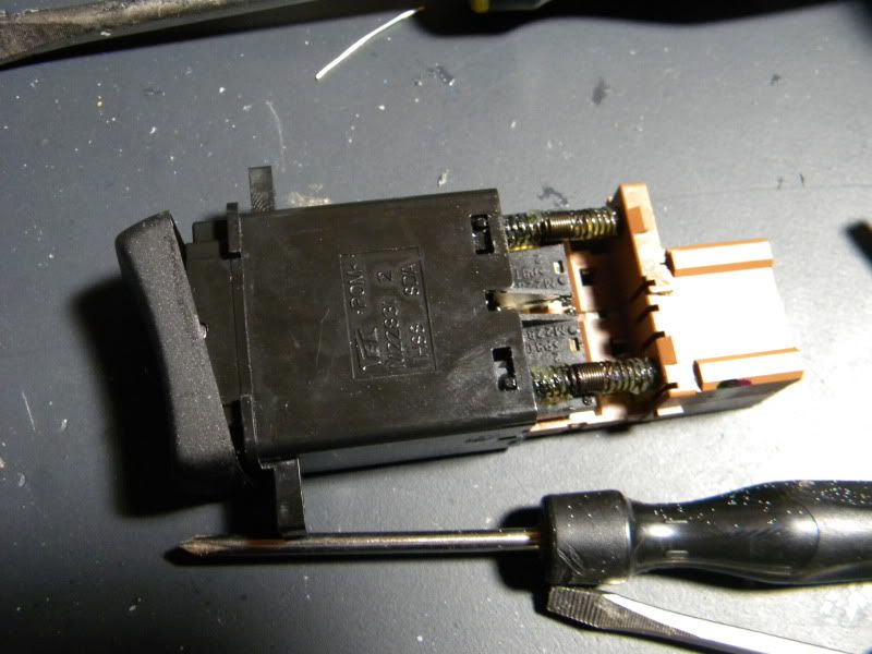
Once this is done, pull the guts out. These things are in there TIGHT. Like mil-spec tight. I don't know why they didn't take this same balls-to-the walls approach with the other lights, but DAMN. Anyway, take 'em out.
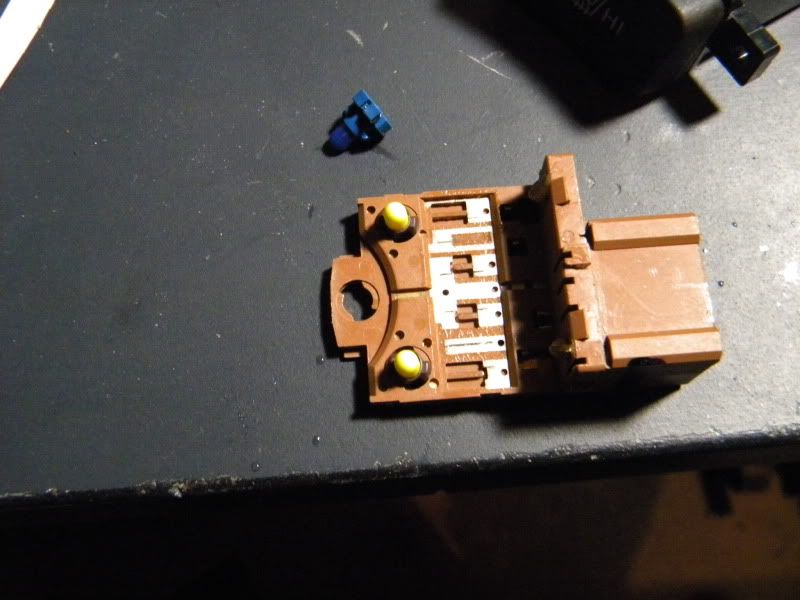
STEP III � SHE LIKES IT ROUGH
Unlike other areas in the TL, the copper leads are quite smooth, which makes soldering impossible as there's no means to bind the solder. SOOOOO, take some 120-grit sandpaper, and rough her up. Apply your solder now, it'll make things easier towards the end.
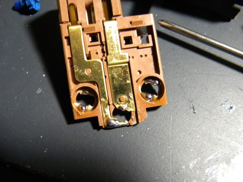
STEP IV � PIECING HUMPTY-DUMPTY BACK TOGETHER AGAIN
Ok, so, I've dealt with some SOB switches that are like a Chinese-rubiks-cube-trap to put back together again, but the gents at Acura made this quite easy. Align the switch triggers in to the inner channel, then seat the switches on the conical positioners on the bottom. Boo-ya, now we can get to work.
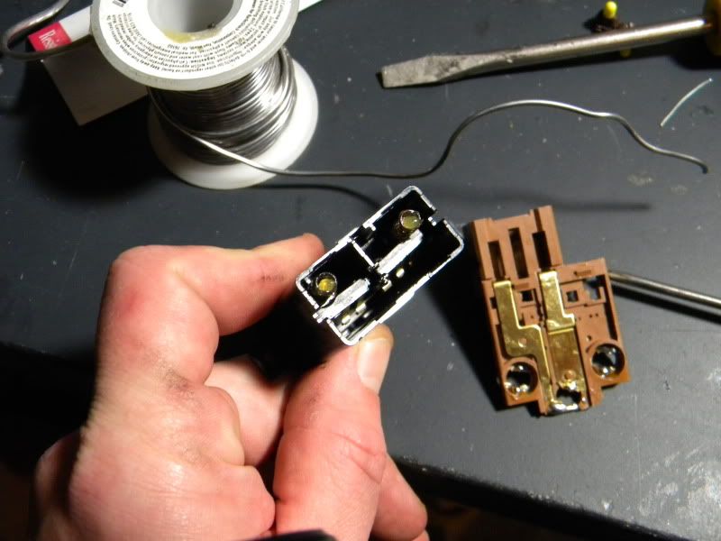
STEP V � LOVE THE TWISTIES
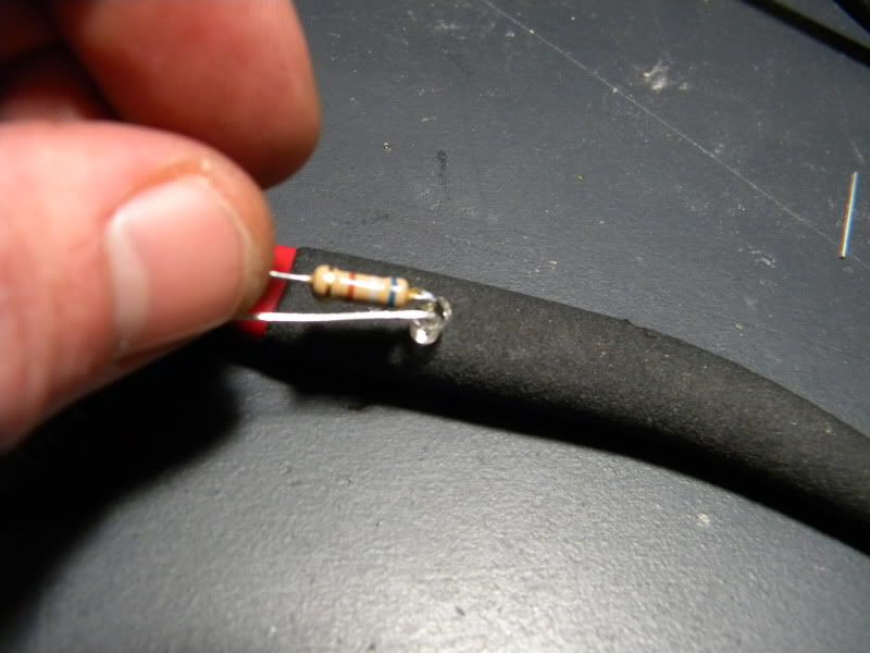
Take the leads and bend at the base, then cut and solder your resistor at the cathode end.
STEP VI � STEADY AS SHE GOES
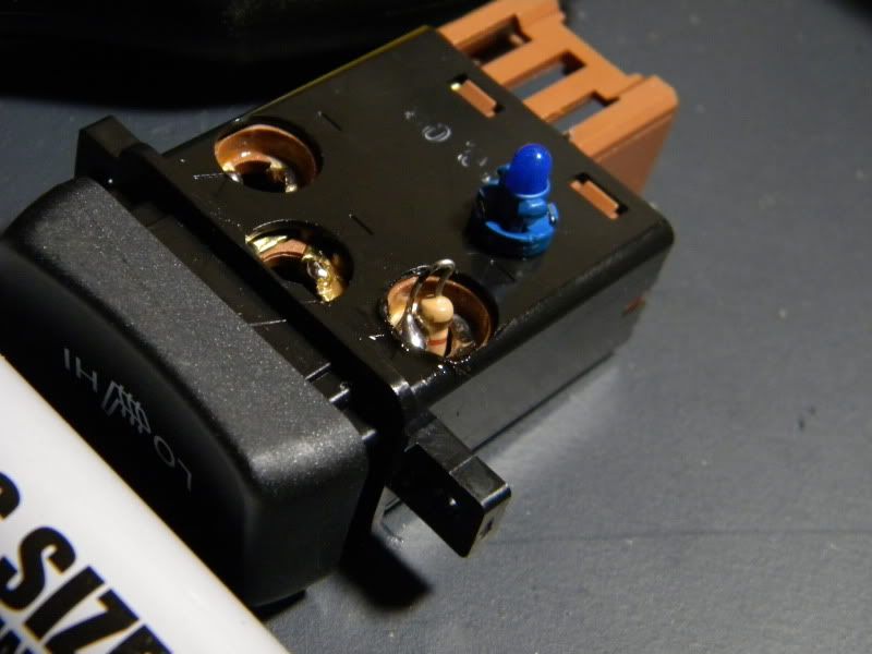
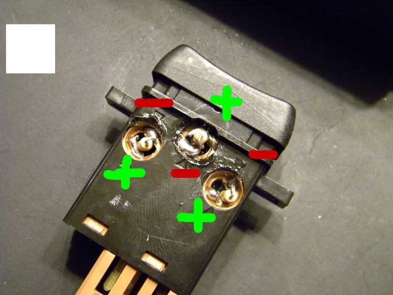
Ok, fit your LED in to position and fire up the soldering iron and fire away. I included the polarity in the second pic, you can buy me a beer later. TAKE YOUR TIME. Once you have the LED in, plug her in and make sure you retain functionality within the switch. The trigger may interfere with the LED, so TEST before you finish. Use a tootchpick to push the LED around if the LED output is not centered...no sense in using this method if we're not eliminating hotspots, that IS the point of this, remember???
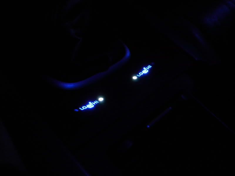
STEP VII � ENJOY!
Ahhh, we're done yet another one. Here's a teaser of the next mod as well, I'll post that one tomorrow night.
Thanks go to dwb993 for specifying the exact bulbs to use.
LET'S GO!
TOOLS NEEDED
Flat head screwdriver
Soldering Iron
MATERIALS
6 x 3mm bulb to your liking...I am used wide-angle flat headed 3mm bulbs
Solder
FLUX, I CANNOT STRESS THIS ENOUGH
TIME
About 1 hours per switch, not counting the time it took to get to it.
STEP I - GETTIN' TO THE GOOD STUFF
Well, there's a little bit of work involved, but it's not too bad as only 4 screws need to be taken out as well as the console. CLICK HERE FOR THE THREAD. It's not hard. For cereal.
STEP II � MIL SPEC VS. WTF
Now, popping out the main illumination button is quite easy...but the indicator lights? EHHHHH, not so much. Take out the first light...then use some flat-headed screwdrivers to pop the button open.
Once this is done, pull the guts out. These things are in there TIGHT. Like mil-spec tight. I don't know why they didn't take this same balls-to-the walls approach with the other lights, but DAMN. Anyway, take 'em out.
STEP III � SHE LIKES IT ROUGH
Unlike other areas in the TL, the copper leads are quite smooth, which makes soldering impossible as there's no means to bind the solder. SOOOOO, take some 120-grit sandpaper, and rough her up. Apply your solder now, it'll make things easier towards the end.
STEP IV � PIECING HUMPTY-DUMPTY BACK TOGETHER AGAIN
Ok, so, I've dealt with some SOB switches that are like a Chinese-rubiks-cube-trap to put back together again, but the gents at Acura made this quite easy. Align the switch triggers in to the inner channel, then seat the switches on the conical positioners on the bottom. Boo-ya, now we can get to work.
STEP V � LOVE THE TWISTIES
Take the leads and bend at the base, then cut and solder your resistor at the cathode end.
STEP VI � STEADY AS SHE GOES
Ok, fit your LED in to position and fire up the soldering iron and fire away. I included the polarity in the second pic, you can buy me a beer later. TAKE YOUR TIME. Once you have the LED in, plug her in and make sure you retain functionality within the switch. The trigger may interfere with the LED, so TEST before you finish. Use a tootchpick to push the LED around if the LED output is not centered...no sense in using this method if we're not eliminating hotspots, that IS the point of this, remember???
STEP VII � ENJOY!
Ahhh, we're done yet another one. Here's a teaser of the next mod as well, I'll post that one tomorrow night.


Trending Topics
12-07-2009, 10:03 PM
#8
Team Owner
iTrader: (2)
Join Date: Jan 2008
Location: Kansas City, MO (Overland Park, KS)
Posts: 36,545
Received 6,470 Likes
on
5,162 Posts
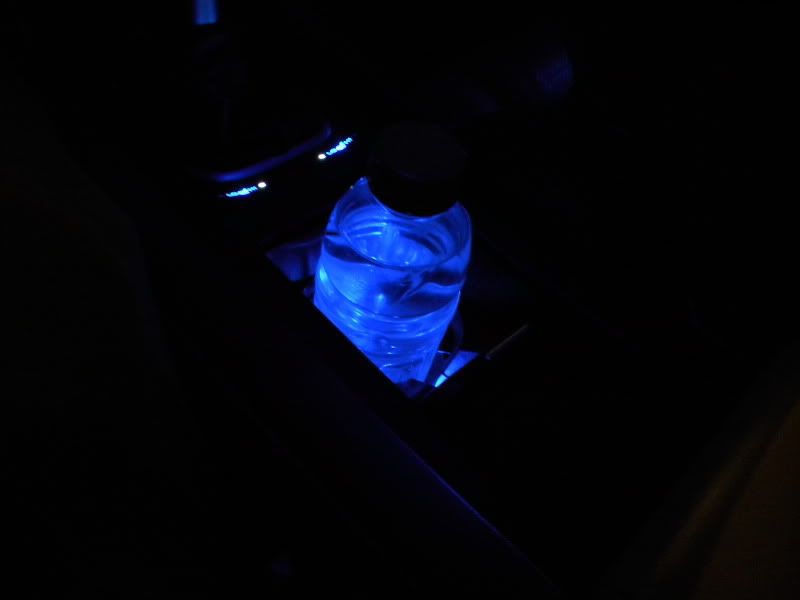
Love the LED's in the cup holders.


Thread
Thread Starter
Forum
Replies
Last Post
cycdaniel
1G TSX Performance Parts & Modifications
8
12-17-2019 10:58 AM
rockyboy
2G RDX (2013-2018)
46
01-25-2016 06:00 PM
handsom-hustla
Car Parts for Sale
70
11-13-2015 05:04 PM