
G-100: DIY LED Interior Conversion, Part II: Rear Door Window Switch w/ Handle LEDs
 10-04-2009, 08:00 PM
#1
Fearless DIY Guy
Thread Starter
iTrader: (2)
G-100: DIY LED Interior Conversion, Part II: Rear Door Window Switch w/ Handle LEDs
Ok, for our next installment we are going to be spending copious amounts of time to change out one tiny little LED...but let's not stop there, shall we? We're also going to be adding some RL-esque flava to the TL by installing an extra LED to the door handle and adding auxilliary wiring for an LED strip in the door pockets.
Thanks go to dwb993 for specifying the exact bulbs to use.
LET'S GO!
TOOLS NEEDED
Dremel
Soldering Iron
Angle cutters
Flat head screwdriver
T10 Torx Driver
Drill
1/8" Bit
Razor blade
MATERIALS
5 x 3mm bulbs to your liking...I am used wide-angle flat headed 3mm bulbs
Solder
FLUX, I CANNOT STRESS THIS ENOUGH
2.2k-ohm resistor
About 6 feet of cheapo Radioslack speaker wire
Shrink tubing
Electrical Tape
TIME
This portion can be fully completed in under 120 minutes ...probably faster, but I'm hungover something fierce today.
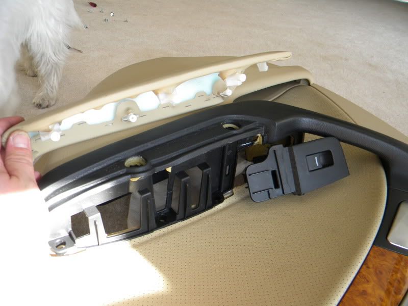
STEP I - PANEL BE GONE!
Ok, you'll need to pop the panel off...there's an FSM link somewhere on here. You'll need to remove 4 screws, one small cover panel, then pull and pop. Nothing major here. Oh, wait, yes there is. The screw on the door handle is at a just plain retarded angle and the bumper stop screw may have been torqued too tightly, so you'll need a set of pliers to hold the base in position while you remove the screw. Good job, union assemblers.
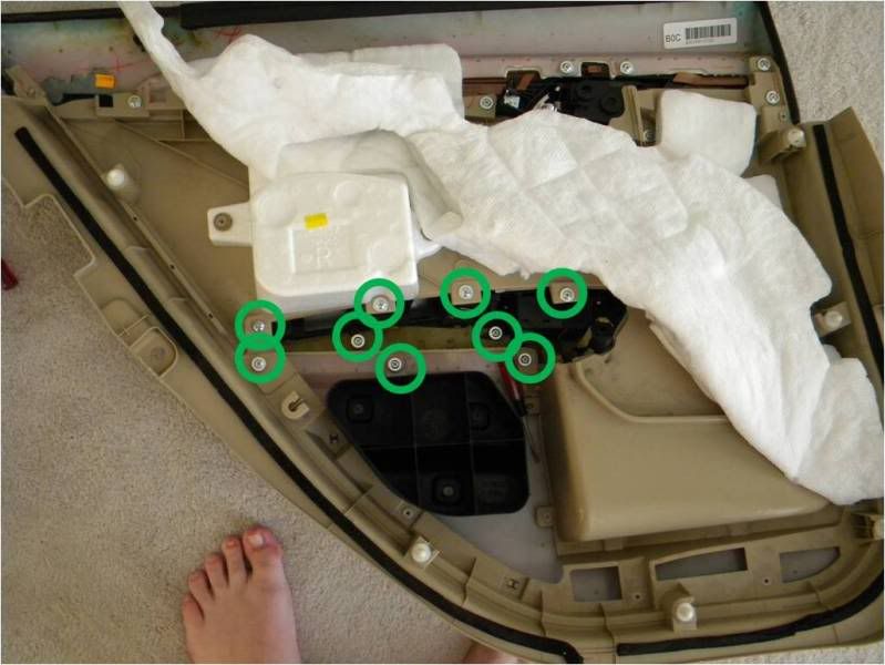
STEP II - BURIAL PROCESS, REVERSED
Jeez...look at this thing...BURIED beneath the mess. Well, we obviously have some work ahead of us here. I tried removing the door switch without having to take any of the individual panels off, but gave up as I was more interested in getting to the switch and seeing what else was under there. Next panel I will be trying a faster route, as this, IMHO, is just plain silly and a total waste of time to get to one tiny-ass switch. BAH. Take off the eleventy-billion screws, then pop the arm rest and switchplate cover off.
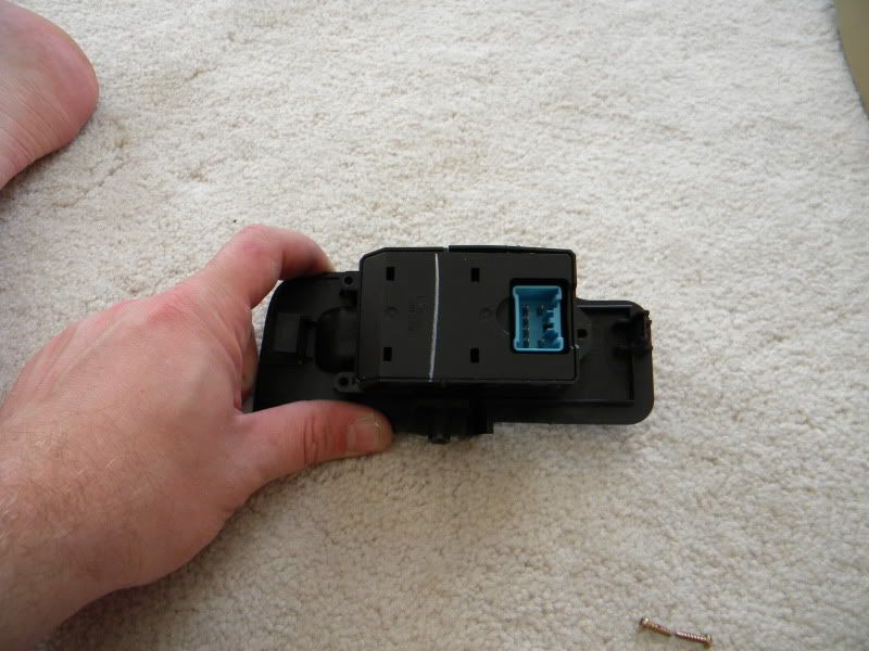
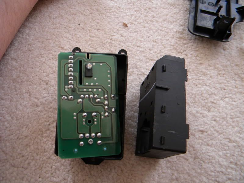
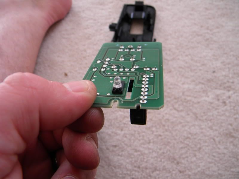
STEP III - GUTTING THE COVER
Ok, we need to remove the board, so we're going to use some flathead screwdrivers to pry open the sides and pull out. I am impressed, however, at the engineers foresight of having a recess in the plastic to allow for the base to flex for removal. Good job, guys.
 [/B]
[/B]
Thanks go to dwb993 for specifying the exact bulbs to use.
LET'S GO!
TOOLS NEEDED
Dremel
Soldering Iron
Angle cutters
Flat head screwdriver
T10 Torx Driver
Drill
1/8" Bit
Razor blade
MATERIALS
5 x 3mm bulbs to your liking...I am used wide-angle flat headed 3mm bulbs
Solder
FLUX, I CANNOT STRESS THIS ENOUGH
2.2k-ohm resistor
About 6 feet of cheapo Radioslack speaker wire
Shrink tubing
Electrical Tape
TIME
This portion can be fully completed in under 120 minutes
...probably faster, but I'm hungover something fierce today. STEP I - PANEL BE GONE!
Ok, you'll need to pop the panel off...there's an FSM link somewhere on here. You'll need to remove 4 screws, one small cover panel, then pull and pop. Nothing major here. Oh, wait, yes there is. The screw on the door handle is at a just plain retarded angle and the bumper stop screw may have been torqued too tightly, so you'll need a set of pliers to hold the base in position while you remove the screw. Good job, union assemblers.
STEP II - BURIAL PROCESS, REVERSED
Jeez...look at this thing...BURIED beneath the mess. Well, we obviously have some work ahead of us here. I tried removing the door switch without having to take any of the individual panels off, but gave up as I was more interested in getting to the switch and seeing what else was under there. Next panel I will be trying a faster route, as this, IMHO, is just plain silly and a total waste of time to get to one tiny-ass switch. BAH. Take off the eleventy-billion screws, then pop the arm rest and switchplate cover off.
STEP III - GUTTING THE COVER
Ok, we need to remove the board, so we're going to use some flathead screwdrivers to pry open the sides and pull out. I am impressed, however, at the engineers foresight of having a recess in the plastic to allow for the base to flex for removal. Good job, guys.
[/B]
 10-04-2009, 08:06 PM
#2
Fearless DIY Guy
Thread Starter
iTrader: (2)
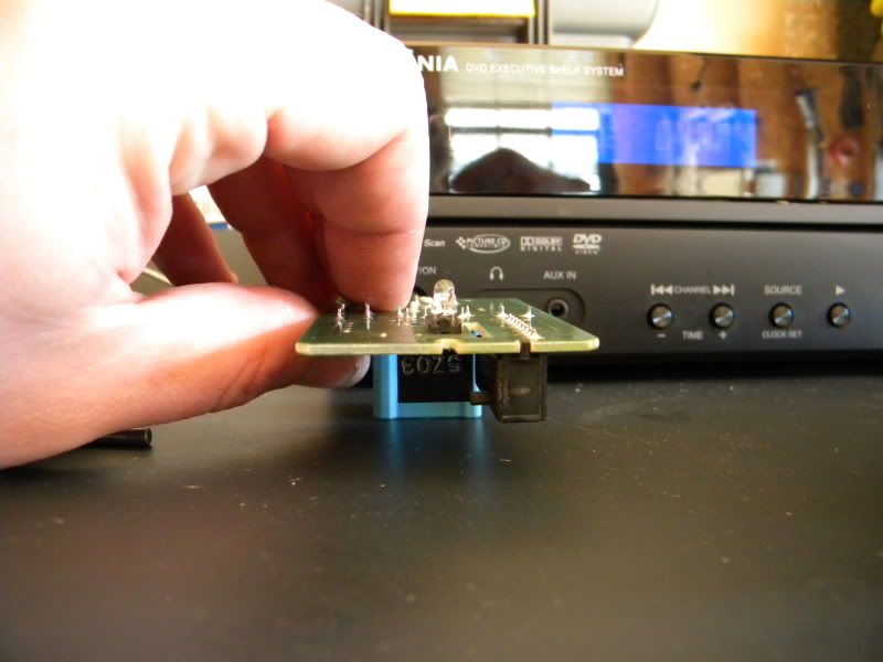
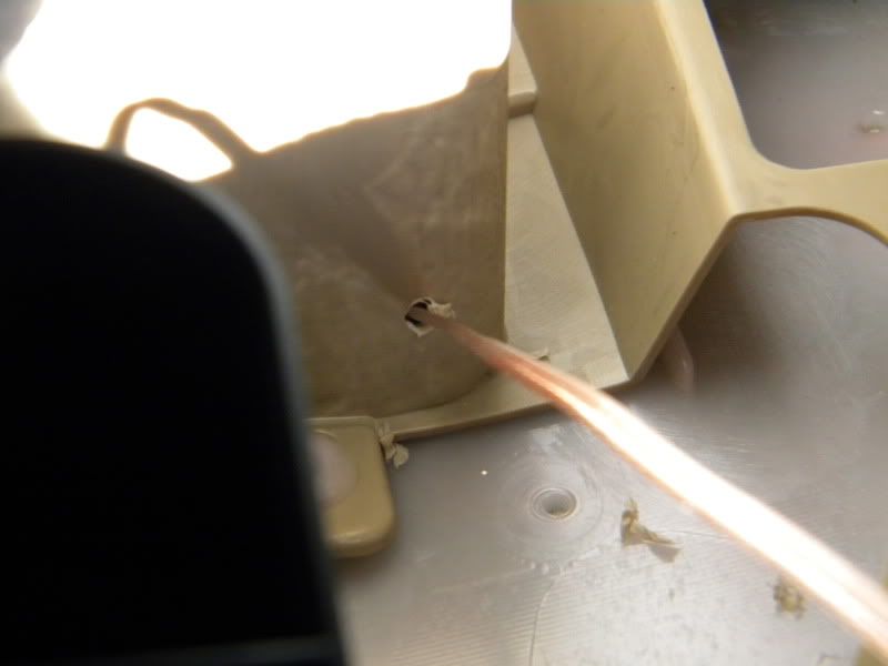
STEP IV - PAGING DOCTOR TO THE OR
Had too much coffee today? Maybe too many smokes? The missus piss you off? If so, STOP NOW. You're gonna need some steady hands, fellas. Here we can see the lovely OE LED. WHY IN THE HELL DIDN'T YOU PUT LEDS IN EVERYTHING TO BEGIN WITH, ACURA?! /rant. Anyway, we're gonna need some *snip* *snip* action to get it off, I recommend a dremel cutting wheel. Why? Cutters will compress before cutting, and we need nice, straight lines to get the LED properly aligned during resolder. Take a deep breath, aaaaand...GO.
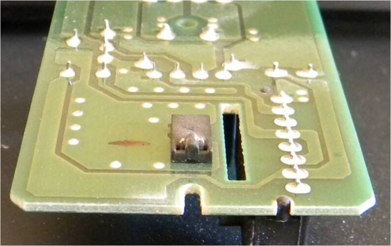
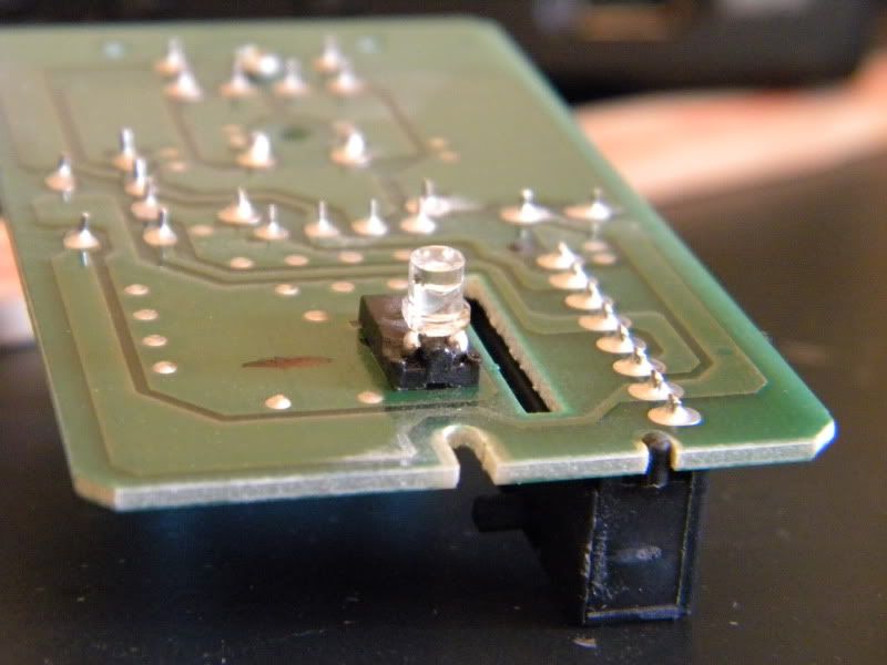
STEP V - NEEDS TO BE WET FOR SUCH A TIGHT FIT
Yep. You heard me. So don't be cheap with the flux here and get those contacts nice and wet. Then heat up your iron and seal the deal.
Had too much coffee today? Maybe too many smokes? The missus piss you off? If so, STOP NOW. You're gonna need some steady hands, fellas. Here we can see the lovely OE LED. WHY IN THE HELL DIDN'T YOU PUT LEDS IN EVERYTHING TO BEGIN WITH, ACURA?! /rant. Anyway, we're gonna need some *snip* *snip* action to get it off, I recommend a dremel cutting wheel. Why? Cutters will compress before cutting, and we need nice, straight lines to get the LED properly aligned during resolder. Take a deep breath, aaaaand...GO.
STEP V - NEEDS TO BE WET FOR SUCH A TIGHT FIT
Yep. You heard me. So don't be cheap with the flux here and get those contacts nice and wet. Then heat up your iron and seal the deal.
10-04-2009, 08:12 PM
#3
Fearless DIY Guy
Thread Starter
iTrader: (2)
STEP VI - RL, TL, LED-L
During my test drives of the TL and RL, I really did appreciate the blue backlight of the door handle, so I thought, "Why let them have all the fun?" So, what we're going to do is rain on their parade and have the same. Prepare an LED by attaching the 2.2k-ohm resistor to the cathode end, solder, shrink, and tape. We're using 2.2k-ohm because we want this to be SUBTLE.
STEP VII - THIS IS WHY WE CAN'T HAVE NICE THINGS
WARNING, MASSIVE RETARDATION OCCURRING HERE!!! Why? Well, you're going to need to drill a hole in the handle, but for the love of God (or diety of your liking), DON'T DRILL WHERE I DID. You'll find out why soon...this will have to be redone, and you'll see why at the end. FUCK!
We're also running a secondary wire to the pocket, but we're waiting to finish that up later this week...
10-04-2009, 08:15 PM
#4
Fearless DIY Guy
Thread Starter
iTrader: (2)
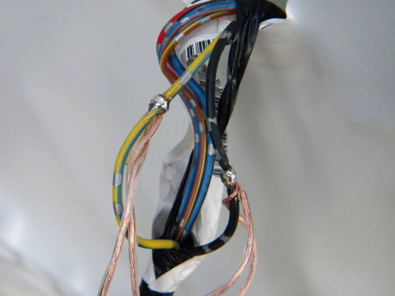
STEP IX - SOLDER & SPLICE, AND EVERYTHING NICE
We're going to tap in to the OE leads for your two wires, solder, and tape. I simply used a straight razor and raw, manly finger pinching to remove the covering. FLUX, solder, tape. Blue & yeller for powah, black for earth.
We're going to tap in to the OE leads for your two wires, solder, and tape. I simply used a straight razor and raw, manly finger pinching to remove the covering. FLUX, solder, tape. Blue & yeller for powah, black for earth.
10-04-2009, 08:20 PM
#5
Fearless DIY Guy
Thread Starter
iTrader: (2)
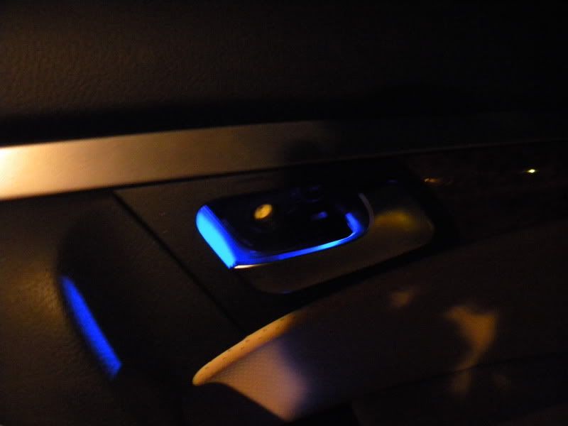
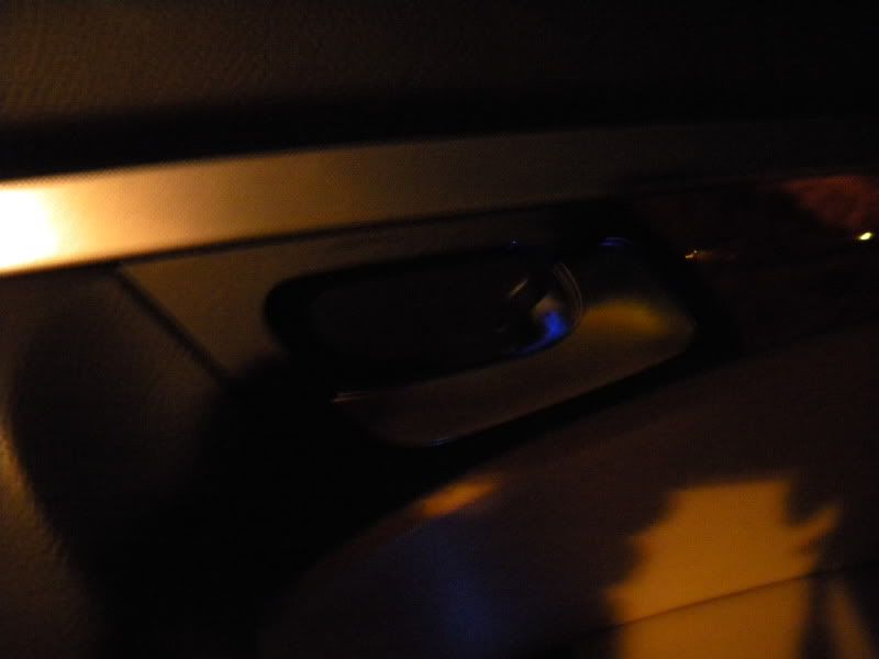
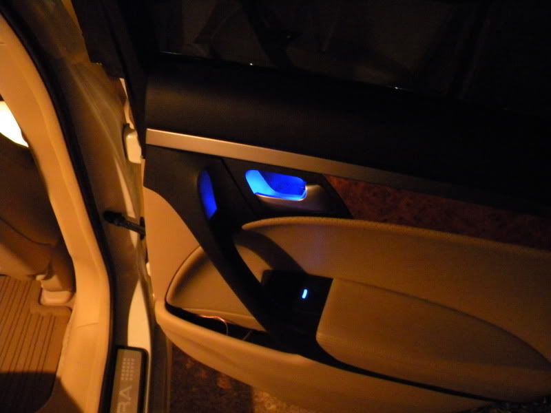
STEP X - ARRRRRGGGGGHHHH
Well, now's time to button her all up. So we have our wire leading in to the pocket...we're waiting on some LED flex strips for there. Our OE button is now a nice, new, updated blue with NO localized glow...but where's the RL look? OHHHH...AWESOME, DAN! YOU PUT IT BEHIND THE COVER PLATE!!! Yeah, my bad. We'll take care of her later on this week, maybe during lunch break on Tuesday or Thursday.
Anyway, we'll be back! Next up is finishing up this and the other door, methinks we're off to the cluster housing and thereabouts next, hopefully this week!

Trending Topics
 10-05-2009, 10:49 PM
#11
takin care of Business in
iTrader: (5)
Join Date: Jan 2008
Location: Kansas City, MO
Age: 40
Posts: 30,994
Received 4,732 Likes
on
4,064 Posts
dude where the fawk are you located.....lets do both cars at the same time....you do yours and i will do mine 
10-11-2009, 08:01 PM
#12
Fearless DIY Guy
Thread Starter
iTrader: (2)

Step VIII was supposed to be me taking a pic of where to drill the holes, but well, I was too anxious and didn't take pics. When I do the front doors I will cover this. Enjoy!
 01-23-2010, 11:41 PM
#13
Fearless DIY Guy
Thread Starter
iTrader: (2)
UPDATE: NOTE FOR THOSE USING WHITE LEDS
I hate to bump all of the threads, but there is an important item that needs to be noted; some of the white LEDs have been burning out, which can be attributed to one thing and one thing only: thermal overload. Therefore,
IT IS HIGHLY RECOMMENDED THAT A 1K-OHM RESISTOR BE USED FOR ALL WHITE LEDS.
I have begun the process of replacing LEDs/resistors for the dearly-departed and can state that the new resistors seem to do the trick.
 10-18-2011, 09:53 PM
#15
Fearless DIY Guy
Thread Starter
iTrader: (2)
Well, there's a douchey move if I ever saw one. Pretty swell to pick a thread with a ton of DIYs listed (you know the one I'm referring to) and "inconspicuously" bump two of them up.
DON'T BUMP DIYS TO GET TO YOUR 15 POSTS, WHEN WE SEE A DIY GET BUMPED, IT TYPICALLY MEANS 'SOS, HELP ME'.
DON'T BUMP DIYS TO GET TO YOUR 15 POSTS, WHEN WE SEE A DIY GET BUMPED, IT TYPICALLY MEANS 'SOS, HELP ME'.
10-18-2011, 10:14 PM
#16
takin care of Business in
iTrader: (5)
Join Date: Jan 2008
Location: Kansas City, MO
Age: 40
Posts: 30,994
Received 4,732 Likes
on
4,064 Posts
^^^ ahahah...
I think Bosco is new and wants to do this to his car...and just said nice thread....I dont think post count has anything to do with his post (or mine) LMAO !!!
This is a great post btw DM
I think Bosco is new and wants to do this to his car...and just said nice thread....I dont think post count has anything to do with his post (or mine) LMAO !!!
This is a great post btw DM


Thread
Thread Starter
Forum
Replies
Last Post
handsom-hustla
Car Parts for Sale
70
11-13-2015 05:04 PM
Yumcha
Automotive News
2
09-04-2015 08:03 AM

