
G-029: '07-'08 Acura TL DIY Fog light Mod
 01-28-2012, 04:02 PM
#1
G-029: '07-'08 Acura TL DIY Fog light Mod
This modification will allow the owner to have full control of the fog lights with the factory switch WITHOUT adding a relay harness.
DISCLAIMER: This write up is only a proposal. I have yet to do this mod. I do not take responsibility for the results of this write up.
With that said, here is what I propose.....
Using a combination of many hours of reading through the 07-08 Acura TL manual, help from Bearcat94 and two different threads posted by Roger555 & donnieb83 I formulated the following DIY. ..... (many thanks to roger555, donnieb83, and bearcat94 ! )
-------------------------------------------------------
PURPOSE (of mod)
To allow independent use of OEM fog lights while maintaing use of the factory combination switch and WITHOUT having to install a relay harness.
Following this DIY will enable you to turn your fog lights on/off anytime (full control) once the ignition is hot. Once your keys are removed, power to the lights are cut. FYI turning your High Beams on will not turn off the fog lights.
Fitment
07-08 Acura TL 3.2 (3.5?)
MATERIALS
Solder & Heat Shrink Tubing
14g Extension Wire
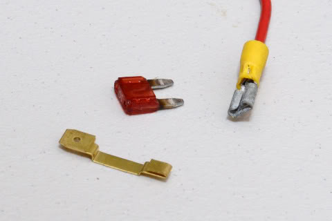
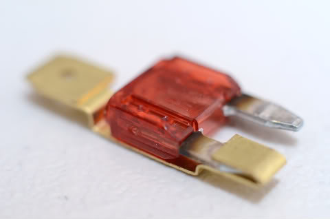
1 ATC Fuse tap NOTE:You are going to need the ATM (mini fuse) model since the TL uses small mini fuses vs the larger fuses ATC of some other cars.
1 female connector
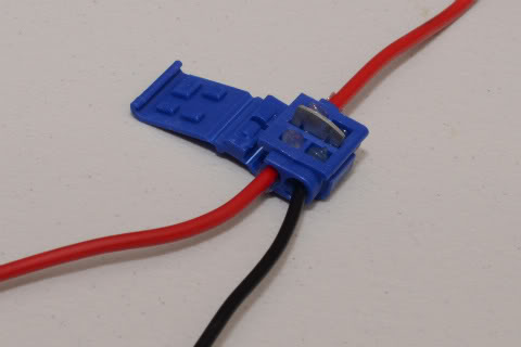
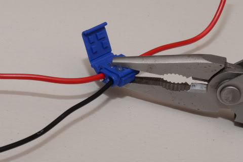
OPTIONAL Splice Tap
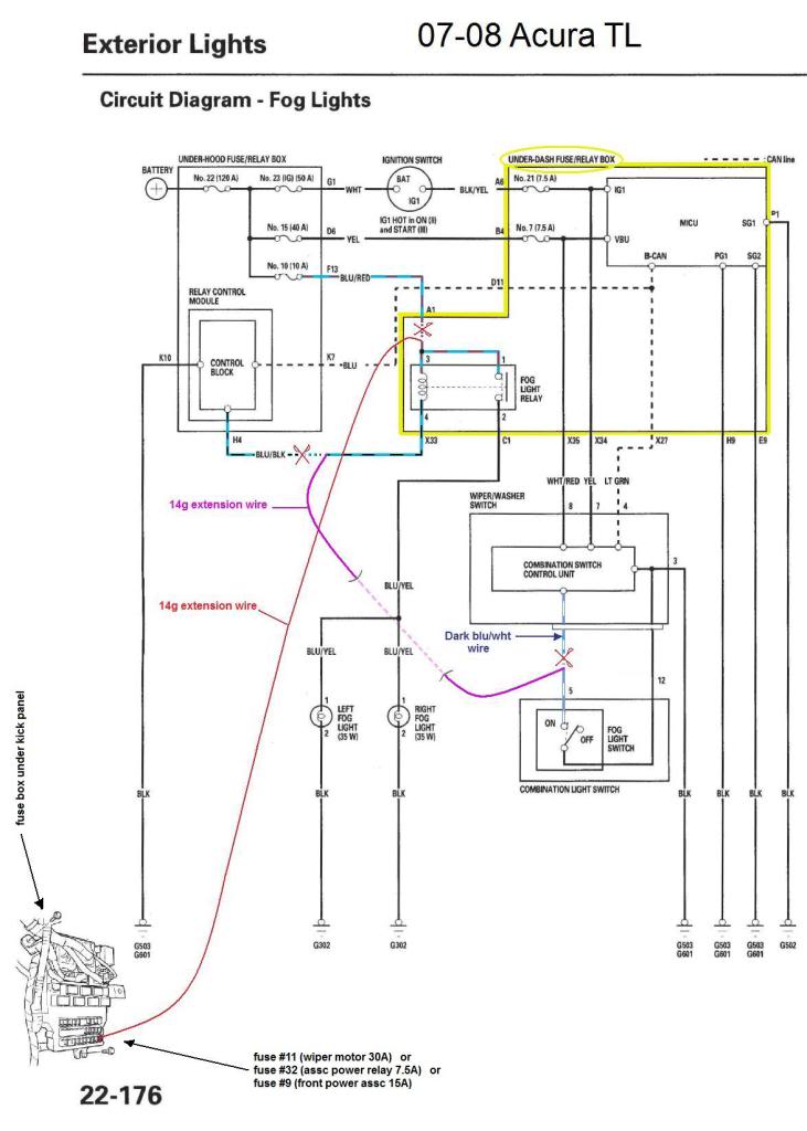
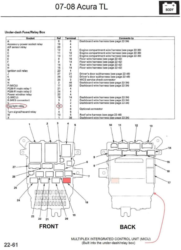
This following diagram and wire colors are the exact same as ROGER555 (04-06 TL diagram) Only difference ... location of the Fog Light Relay.
NOTE: Before beginning, I would recommend disconnecting the car battery. Before doing so, make sure you have the radio security code.
You will probably need to re-enter the code after connecting the battery.
Step 1:
Remove the under dash panel.
Step 2:
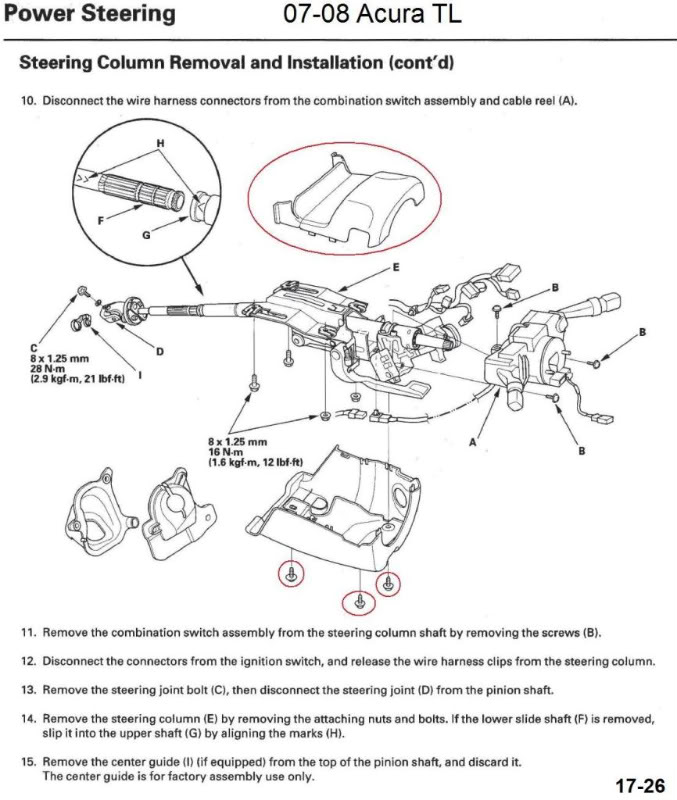
Remove the plastic cover surrounding the base of the steering wheel. There are 3 screws and clips around the edge where the two
halves meet.
Step 3:
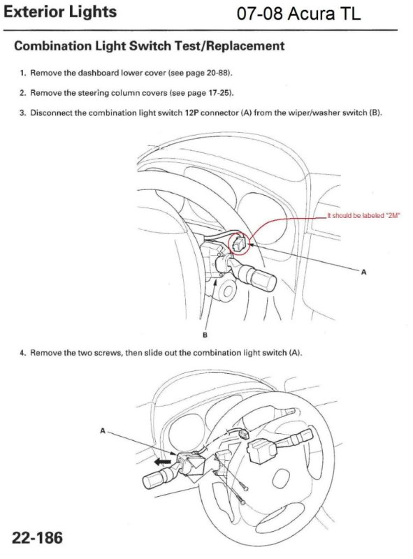
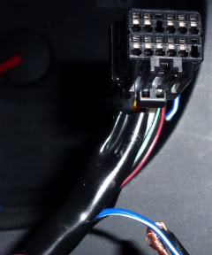
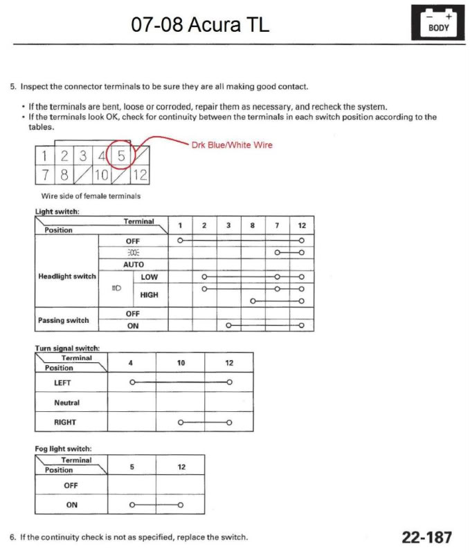
Locate the combination switch (left of steering wheel)..... follow the wiring from the combination switch to the right back side of the steering column.... it should lead to a plug (near ignition switch) It SHOULD say “2M” on it. Unplug it, and cut the Dark Blue/white wire (NOT THE Lt blu/white wire). Solder your 14g extension wire to the Dark Blue/white wire (the end that IS attached to the plug). Heat shrink tube your connection. Tape up the end of the wire that you cut (the end NOT sticking out of the plug). Run your extension wire down the column, under the dash towards the fuse box panel.
Harness from a 07-08. donnieb83 says the wire is dark blue/white (DO NOT cut the Lt blu/wht wire)
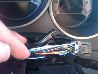
This harness is from an 04-06. roger555 says the wire is dark blue/white (do NOT use Lt blu/wht wire)
Step 4:
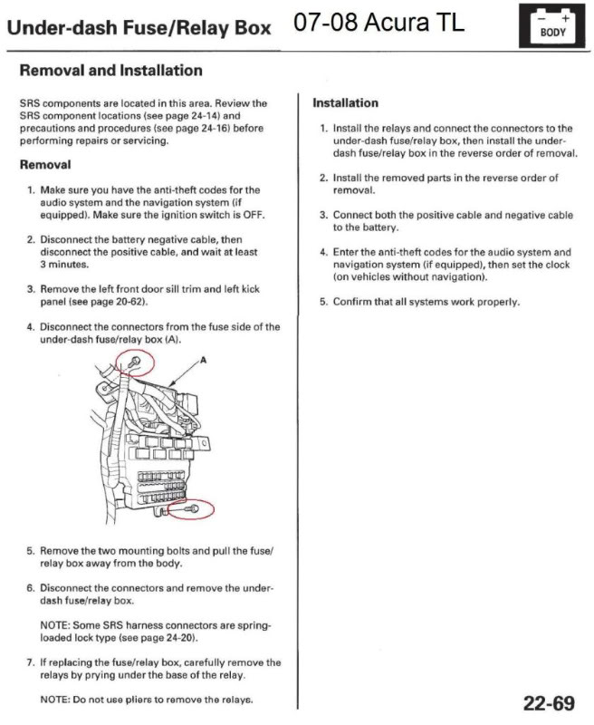
Remove the two screws to the Fuse Panel (to gain access to the back of the panel.)
Step 5:
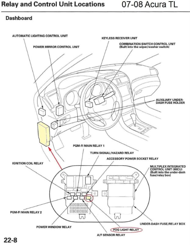
Find the Fog Light Relay on the front of the panel... on the back side of the panel in the same location you should be able to spot a blu/blk wire, and a blu/red wire. These are the wires you want. (This section of the panel are integrated into the panel. You will not be able to simply unplug a harness.)
Step 6:
Find the blue/black wire behind the Fog Light Relay and cut it. Solder your14g extension (from Dark Blue/white wire of Combination Switch) to the end of the blue/black wire sticking out of the back the fog light relay. Tape off the other loose end of the blue/black wire with electrical tape (the end not sticking out of the back of the fog light relay). It will remain unconnected.
Step 7: (**there is a different option for this step, see the end of this post):
Find the blue/red wire behind the Fog Light Relay and cut it. Solder a second 14g extension wire to the end of the blue/red wire sticking out of from behind the fog light relay. Tape off the other loose end of the blue/red wire (not sticking out of the fog light relay) with electrical tape. This end will remain unconnected.
Step 8:
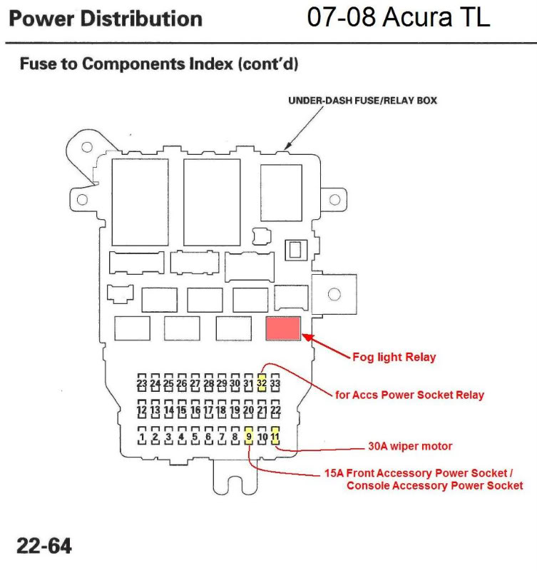
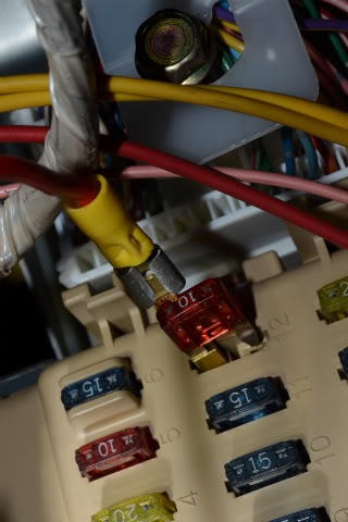
Take fuse out of the #11 spot on fuse box panel. Crimp a female connector to the end of your second wire extension (the one that is soldered to the blue/red wire). Insert the fuse into the ATM Fuse tap. Then insert the fuse/and tap into the female connector attached to your second extension wire. Re-insert your wire taped fuse back into the fuse #11 hole (wiper motor 30A).
NOTE: you can also use fuse hole #32 (Accessory Power Socke Relay fuse hole 7.5A) or fuse hole #9 (Front Accessory Power Socket 15A)
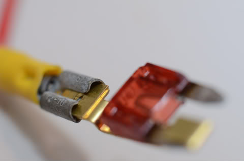
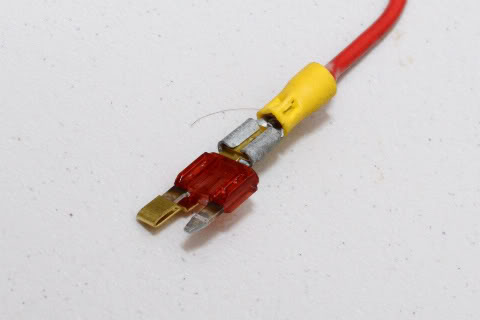
The image above is not that of an Acura TL. (for example only)
Step 9:
Re-connect battery. Re-enter radio code. Test lights.... with the ignition on, the fog lights should be on (if switched on) with parking lights, low beams, or high beams.
NOTE:The Fog light indicator on the dash will not illuminate. (the indicator function has been disabled due to bypassing the Control Unit with the new extension wire from the combination light switch stalk.)
STEP 7: (SECOND OPTION)
NOTE: doing this option eliminates the original step #7 and #8
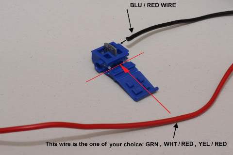
Find the blue/red wire behind the Fog Light Relay and cut it. Use a Splice Tap and connect the loose end of the blu/red wire (coming from back of relay) to either the:
(Yel/Red) wire behind fuse socket #32
or
(grn) wire behind fuse socket #11
or
(wht/red) wire behind fuse socket #9
NOTE: You will not need to cut the (yel/red), (grn), or (wht/red) wires.... simply use the Splice Connecter to tap the wire of your choice to the blu/red wire (connected to the fog light relay). The blu/red fog light wire is only a remote wire, not a power wire. You shouldn't need an extension for Step 7 Option because all the wires for this option are all behind the fuse box panel. Last, tape off the remaining loose end of the blu/red wire (not coming from the back of the relay)... you will no longer use this end.
Continue to step 9 above.
GOOD LUCK!
DISCLAIMER: This write up is only a proposal. I have yet to do this mod. I do not take responsibility for the results of this write up.
With that said, here is what I propose.....
Using a combination of many hours of reading through the 07-08 Acura TL manual, help from Bearcat94 and two different threads posted by Roger555 & donnieb83 I formulated the following DIY. ..... (many thanks to roger555, donnieb83, and bearcat94 ! )
-------------------------------------------------------
PURPOSE (of mod)
To allow independent use of OEM fog lights while maintaing use of the factory combination switch and WITHOUT having to install a relay harness.
Following this DIY will enable you to turn your fog lights on/off anytime (full control) once the ignition is hot. Once your keys are removed, power to the lights are cut. FYI turning your High Beams on will not turn off the fog lights.
Fitment
07-08 Acura TL 3.2 (3.5?)
MATERIALS
Solder & Heat Shrink Tubing
14g Extension Wire
1 ATC Fuse tap NOTE:You are going to need the ATM (mini fuse) model since the TL uses small mini fuses vs the larger fuses ATC of some other cars.
1 female connector
OPTIONAL Splice Tap
This following diagram and wire colors are the exact same as ROGER555 (04-06 TL diagram) Only difference ... location of the Fog Light Relay.
NOTE: Before beginning, I would recommend disconnecting the car battery. Before doing so, make sure you have the radio security code.
You will probably need to re-enter the code after connecting the battery.
Step 1:
Remove the under dash panel.
Step 2:
Remove the plastic cover surrounding the base of the steering wheel. There are 3 screws and clips around the edge where the two
halves meet.
Step 3:
Locate the combination switch (left of steering wheel)..... follow the wiring from the combination switch to the right back side of the steering column.... it should lead to a plug (near ignition switch) It SHOULD say “2M” on it. Unplug it, and cut the Dark Blue/white wire (NOT THE Lt blu/white wire). Solder your 14g extension wire to the Dark Blue/white wire (the end that IS attached to the plug). Heat shrink tube your connection. Tape up the end of the wire that you cut (the end NOT sticking out of the plug). Run your extension wire down the column, under the dash towards the fuse box panel.
Harness from a 07-08. donnieb83 says the wire is dark blue/white (DO NOT cut the Lt blu/wht wire)
This harness is from an 04-06. roger555 says the wire is dark blue/white (do NOT use Lt blu/wht wire)
Step 4:
Remove the two screws to the Fuse Panel (to gain access to the back of the panel.)
Step 5:
Find the Fog Light Relay on the front of the panel... on the back side of the panel in the same location you should be able to spot a blu/blk wire, and a blu/red wire. These are the wires you want. (This section of the panel are integrated into the panel. You will not be able to simply unplug a harness.)
Step 6:
Find the blue/black wire behind the Fog Light Relay and cut it. Solder your14g extension (from Dark Blue/white wire of Combination Switch) to the end of the blue/black wire sticking out of the back the fog light relay. Tape off the other loose end of the blue/black wire with electrical tape (the end not sticking out of the back of the fog light relay). It will remain unconnected.
Step 7: (**there is a different option for this step, see the end of this post):
Find the blue/red wire behind the Fog Light Relay and cut it. Solder a second 14g extension wire to the end of the blue/red wire sticking out of from behind the fog light relay. Tape off the other loose end of the blue/red wire (not sticking out of the fog light relay) with electrical tape. This end will remain unconnected.
Step 8:
Take fuse out of the #11 spot on fuse box panel. Crimp a female connector to the end of your second wire extension (the one that is soldered to the blue/red wire). Insert the fuse into the ATM Fuse tap. Then insert the fuse/and tap into the female connector attached to your second extension wire. Re-insert your wire taped fuse back into the fuse #11 hole (wiper motor 30A).
NOTE: you can also use fuse hole #32 (Accessory Power Socke Relay fuse hole 7.5A) or fuse hole #9 (Front Accessory Power Socket 15A)
The image above is not that of an Acura TL. (for example only)
Step 9:
Re-connect battery. Re-enter radio code. Test lights.... with the ignition on, the fog lights should be on (if switched on) with parking lights, low beams, or high beams.
NOTE:The Fog light indicator on the dash will not illuminate. (the indicator function has been disabled due to bypassing the Control Unit with the new extension wire from the combination light switch stalk.)
STEP 7: (SECOND OPTION)
NOTE: doing this option eliminates the original step #7 and #8
Find the blue/red wire behind the Fog Light Relay and cut it. Use a Splice Tap and connect the loose end of the blu/red wire (coming from back of relay) to either the:
(Yel/Red) wire behind fuse socket #32
or
(grn) wire behind fuse socket #11
or
(wht/red) wire behind fuse socket #9
NOTE: You will not need to cut the (yel/red), (grn), or (wht/red) wires.... simply use the Splice Connecter to tap the wire of your choice to the blu/red wire (connected to the fog light relay). The blu/red fog light wire is only a remote wire, not a power wire. You shouldn't need an extension for Step 7 Option because all the wires for this option are all behind the fuse box panel. Last, tape off the remaining loose end of the blu/red wire (not coming from the back of the relay)... you will no longer use this end.
Continue to step 9 above.
GOOD LUCK!
Last edited by Bearcat94; 01-28-2012 at 05:11 PM. Reason: Corrected error in text
 01-28-2012, 04:23 PM
#2
Race Director
iTrader: (8)
Finally.
Awesome job! It'll be useful to 07/08 owners =)
Who's gonna be the first to try it out? haha
Awesome job! It'll be useful to 07/08 owners =)
Who's gonna be the first to try it out? haha
Last edited by guitarplayer16; 01-28-2012 at 04:26 PM.
01-28-2012, 04:48 PM
#4
AZ Community Team

Join Date: May 2007
Location: N35�03'16.75", W 080�51'0.9"
Posts: 32,488
Received 7,770 Likes
on
4,341 Posts

Excellent.
Two questions.
1.) I may be reading this wrong, but I think it's backwards.
".... Solder your 14g extension wire to the Dark Blue/white wire (the end not attached to the plug). Heat shrink tube your connection. Tape up the end of the wire that you cut (the end sticking out of the plug). ...."
Isn't the end of the cut wire that is on the plud side (i.e. the switch side) the one we want? We tap into the switch there and then run our new wire to the Fog Relay in the kick panel. Right?
2.) I'm not so sure about using ACC power at fuse location #32. That is a 7.5A fuse. The original Fog Light fuse (in the Under Hood panel) is 10A. So wouldn't you want something at least 10A?
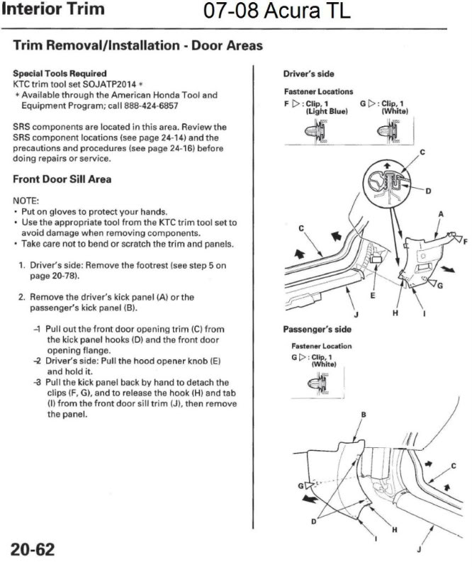
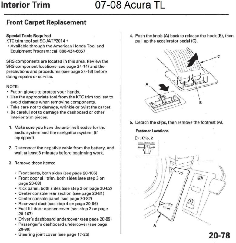
Finally, would you mind posting page 20-62 from the SM for removal of the kick panel and sill?
01-28-2012, 05:03 PM
#6
[quote=Bearcat94;13514819]
CRAP, I had it right in my notes, i don't know how I got it backwards on here. At least my very first diagram is right
You are right sir, it should read
".... Solder your 14g extension wire to the Dark Blue/white wire (the end that IS attached to the plug). Heat shrink tube your connection. Tape up the end of the wire that you cut (the end NOT sticking out of the plug). ...."
I do agree that using the ACC power at fuse location #32 wouldn't be a good idea.
VERY GOOD CATCH HERE.
01-28-2012, 05:08 PM
#7
honestly, all you would 'probably' need is a simple small wire that leads from the stalk to the LED in the back of the speedo cluster. When the stalk get's turned on, it powers up the LED also. That one should probably be pretty easy. I just can't really look into it much right now.
Trending Topics
01-28-2012, 05:12 PM
#8
AZ Community Team
Join Date: May 2007
Location: N35�03'16.75", W 080�51'0.9"
Posts: 32,488
Received 7,770 Likes
on
4,341 Posts
CRAP, I had it right in my notes, i don't know how I got it backwards on here. At least my very first diagram is right
You are right sir, it should read
".... Solder your 14g extension wire to the Dark Blue/white wire (the end that IS attached to the plug). Heat shrink tube your connection. Tape up the end of the wire that you cut (the end NOT sticking out of the plug). ...."
....
I fixed this in the original post. Double check me that I got the correction right.
Also, added this thread to the DIY/FAQ Garage.
The following users liked this post:
jauman (01-28-2012)
The following users liked this post:
Bearcat94 (01-28-2012)
01-28-2012, 05:50 PM
#10
Moderator
iTrader: (7)
honestly, all you would 'probably' need is a simple small wire that leads from the stalk to the LED in the back of the speedo cluster. When the stalk get's turned on, it powers up the LED also. That one should probably be pretty easy. I just can't really look into it much right now.
01-29-2012, 12:00 PM
#11
AZ Community Team
Join Date: May 2007
Location: N35�03'16.75", W 080�51'0.9"
Posts: 32,488
Received 7,770 Likes
on
4,341 Posts
I agree that not having the dash indicator is a minor downside. But compared to, for instance, some of the DRL mods where you have the error light, this is, imo, pretty trivial. The price we have to pay, I guess.
Hope to try this next week-end.
Hope to try this next week-end.
01-29-2012, 04:10 PM
#12
Race Director
iTrader: (8)
Let us know how it goes!
Maybe take some pics to contribute to the DIY?
Maybe take some pics to contribute to the DIY?
The following users liked this post:
jauman (01-30-2012)
The following users liked this post:
jauman (01-30-2012)
The following users liked this post:
donnieb83 (01-30-2012)
03-15-2012, 05:53 PM
#16
Intermediate
Alright trying this mod right now, ran into some difficulty getting to the back of the fuse panel. It seems impossible to get to. I undid all but one connector, the srs one. Idk how to get the spring loaded clip off, If anyone can plz help asap.
.....Alrighty then jut reread through this and I thought this had been done before and it looks like it someone hasnt, so Im putting everything back. :/
.....Alrighty then jut reread through this and I thought this had been done before and it looks like it someone hasnt, so Im putting everything back. :/
Last edited by BOMDC5; 03-15-2012 at 06:02 PM.
03-15-2012, 06:56 PM
#17
Race Director
iTrader: (8)
Alright trying this mod right now, ran into some difficulty getting to the back of the fuse panel. It seems impossible to get to. I undid all but one connector, the srs one. Idk how to get the spring loaded clip off, If anyone can plz help asap.
.....Alrighty then jut reread through this and I thought this had been done before and it looks like it someone hasnt, so Im putting everything back. :/
.....Alrighty then jut reread through this and I thought this had been done before and it looks like it someone hasnt, so Im putting everything back. :/
03-21-2012, 01:59 PM
#19
Intermediate
Decided Im just going to wire it the same way I did it on my rsx. Ill try and take some photos if it works out good. Here a picture as a reference
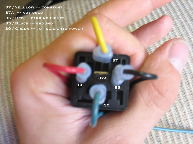
The only downside is the fogs will flash when I lock and unlock my car I.E since the parking lights flash
The only downside is the fogs will flash when I lock and unlock my car I.E since the parking lights flash
03-21-2012, 02:27 PM
#20
Race Director
iTrader: (8)
Instead of hooking the red wire to the parking lights, can't you just hook it up to a constant source?
03-23-2012, 02:12 PM
#21
Intermediate
04-06-2012, 02:25 AM
#22
Cruisin'
I cant seem to find the Blue/Red and Blue/Black I found them on 2 different plugs but didn't want to cut them since it said its not on a plug i pulled apart the fuse box but all i saw was circuit boards and didn't want to mess with them. Can someone give me some guidance to where these wires are on the back?
Thanks
Thanks
04-09-2012, 02:19 PM
#24
Race Director
iTrader: (8)
04-09-2012, 08:27 PM
#25
Cruisin'
Good luck fuse box is all circuit board. Need to find the pinout of the harnesses behind the fuse box. I might tear the car apart this weekend to try to find the right wires for the connectors on the back
05-16-2012, 08:33 PM
#28
OK, 07-08 guys are saying, to tape up the harness end and tap into the plug end
while roger555 clearly taped up his plug end and tapped into his harness end.........whos right???
while roger555 clearly taped up his plug end and tapped into his harness end.........whos right???
05-21-2012, 10:33 AM
#31
Cruisin'

they're both right in that roger555 didn't tape the switch side. please reread his step #2 and review his wiring schematic.
05-21-2012, 10:36 AM
#32
Cruisin'
hold on. i think i see where the confusion is. where you're referring to the "harness side" i'm calling that the "switch side". the "plug side" you refer to is what i refer to as the "harness side" because that leads into additional wire harnesses leading to various fuse panels and control modules. this being the case, yes, roger555 tapped his extension wire to the side that physically goes to the switch and taped ("tapped" and "taped" probably aren't the best choice of words for this diy and explanation) off the wire going to the plug that ultimately leads to the Combination Switch Control Unit. Both diy's are doing the same thing on the steering wheel end of the project.
does that help?
Last edited by cmluckett; 05-21-2012 at 10:48 AM. Reason: i fingered it out (me thinks)
05-21-2012, 01:54 PM
#33
Your post did actually help. I looked at the diagrams a little closer and saw that there is a pigtail that comes from the switch, which in turn plugs into the main harness. Now I fully get it
All along I thought the main harness went directly to a plug on the switch. And that they were just cutting into it (main harness) and doing there extentions from there.
I kept wondering how is the switch able to get power when they just severed the lines and extended the wire that was essentially coming from the fuse panel lol. I completely missed the pigtail.
06-05-2012, 09:21 AM
#35
1st Gear

Join Date: Apr 2012
Age: 47
Posts: 1
Likes: 0
Received 0 Likes
on
0 Posts
Hi I'm new to Azine, attempted this mod, but ran into a road block, relay panel equip with circuit boards no corresponding wires in rear, any suggestions, need help, own a 2008 TL base, thanks
04-29-2013, 02:58 PM
#37
Registered Bike Offender
iTrader: (3)
I plan on doing this mod and creating an extensive write up. I won't have a chance to do this for a couple of weeks yet though. If you don't want to be the guinea pig, I will! 
The only reservations I have about this method is leaving some connections open. It probably doesn't matter, but there is something "dirty" to me about leaving digital control signals floating. There is probably a pull-up or pull-down resistor on the controller side, but I don't like leaving things to chance.
I would also like to retain as much functionality over the dash fog lamp indicator as possible. That said, it should at least work when the headlamps are on, though the indicator will not be on when the fogs are on and headlamps off.
Edit: I forgot to mention that I have the pinout for the harnesses, so all the work should just be soldering wires to wires with no circuit board modifications necessary.
Last edited by Vlad_Type_S; 04-29-2013 at 03:01 PM.
04-29-2013, 04:42 PM
#38
I plan on doing this mod and creating an extensive write up. I won't have a chance to do this for a couple of weeks yet though. If you don't want to be the guinea pig, I will!
The only reservations I have about this method is leaving some connections open. It probably doesn't matter, but there is something "dirty" to me about leaving digital control signals floating. There is probably a pull-up or pull-down resistor on the controller side, but I don't like leaving things to chance.
I would also like to retain as much functionality over the dash fog lamp indicator as possible. That said, it should at least work when the headlamps are on, though the indicator will not be on when the fogs are on and headlamps off.
Edit: I forgot to mention that I have the pinout for the harnesses, so all the work should just be soldering wires to wires with no circuit board modifications necessary.

The following users liked this post:
jauman (06-22-2015)