When you click on links to various merchants on this site and make a purchase, this can result in this site earning a commission. Affiliate programs and affiliations include, but are not limited to, the eBay Partner Network.
Thank You
First of all, I just wanted to say "Thank You" to the previous Acuraziners who have tackled this project in the past. Luckily, I read through all of the threads before Photobucket took away most of the useful images, so the images were engraved in my brain. Even though I still have all of these useful threads bookmarked, most of the images are no longer available... and that's kind of the reason for this post. I wanted to provide some useful images as well as share my input in case anyone has the desire to complete this modification for themselves.
Introduction
For years (yes, literally years), I have wanted to replace the LEDs on my radio circuit board. However, time always got in the way. However, I finally took the plunge. Every bulb on my board was out, except the 4 blue LEDs that illuminated the radio knobs. I literally could not see my radio at night, so I think it’s safe to say that this was overdue.
Tools Needed
-Flat Head Screw Driver
-Philips Head Screw Driver
-LEDs of Your Choice - I used a combination of Blue and White Neo Wedge LEDs that I have used on other projects. I removed the black housings from them, because they need to be soldered to the circuit board. The LEDs I purchased already contain a micro-chip style resistor on the backside of the bulb, so it makes things a little easier. Here is a link to the bulbs I purchased:
Optional (But Highly Recommended) Tools Needed
-Spare Radio
-Multimeter
-Tweezers
-Paper Towel
-A Bright Desk/Working Light
*I should note that I actually purchased a spare radio on eBay for this project. It only set me back around $40, but was well worth it in my opinion. Having a spare radio allowed me to work on the circuit board without having to leave my car in shambles while I worked on this project. I also was much more relaxed at the beginning stages due to the fact that I wasn’t in a time crunch to get the radio re-assembled on the same day. It doesn’t matter if the spare radio is cracked, beaten up, etc. as you only need the circuit board inside the radio. This circuit board is like the command center for the radio’s buttons. Swapping the circuit board is not a “different” radio. The radio and corresponding radio code remains the same.
Step 1: Removing the Radio (This can be done later if you have a spare radio.)
If you don't know how to remove the radio, please watch the following videos. It may seem intimidating at first, but it's actually pretty easy. I can't count the amount of times I've taken apart my dash at this stage of my ownership. I can probably remove my radio in about 6 minutes now.
Part 1:
Step 2: Disassembling the Radio
After removing the radio from the car, the next step is to remove the circuit board from the radio itself. You will need to peel back a small cloth strip on the top and bottom of the radio, which will give you access to four screws. Removing these four screws allows you to unscrew the “face” of the radio, which contains the circuit board.
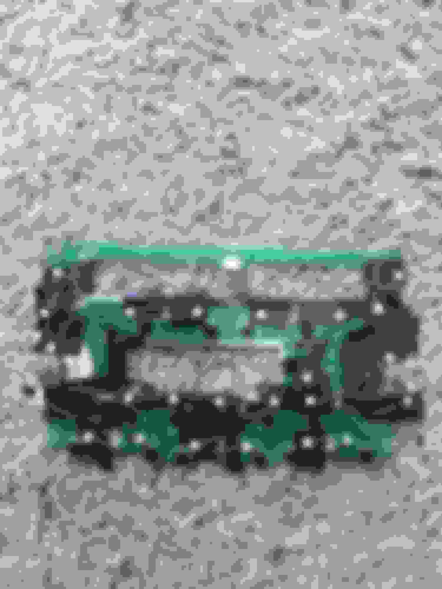
After removing the “face of the radio”, you will need to remove six more screws to detach the circuit board. These six screws are located on the back side and are circled in the below image.
To remove the circuit board, you also need to remove the radio knobs from the face of the radio. This can be done after the six screws are removed. However, I should metion that you’ll find that it’s easier to remove them before you unscrew the circiut board. Simply pull the radio knobs straight outward with some force. It may seem like you are going to break the knobs off. However, there are no clips holding these nobs in place. So, as long as you pull the knobs straight out, you should be okay.
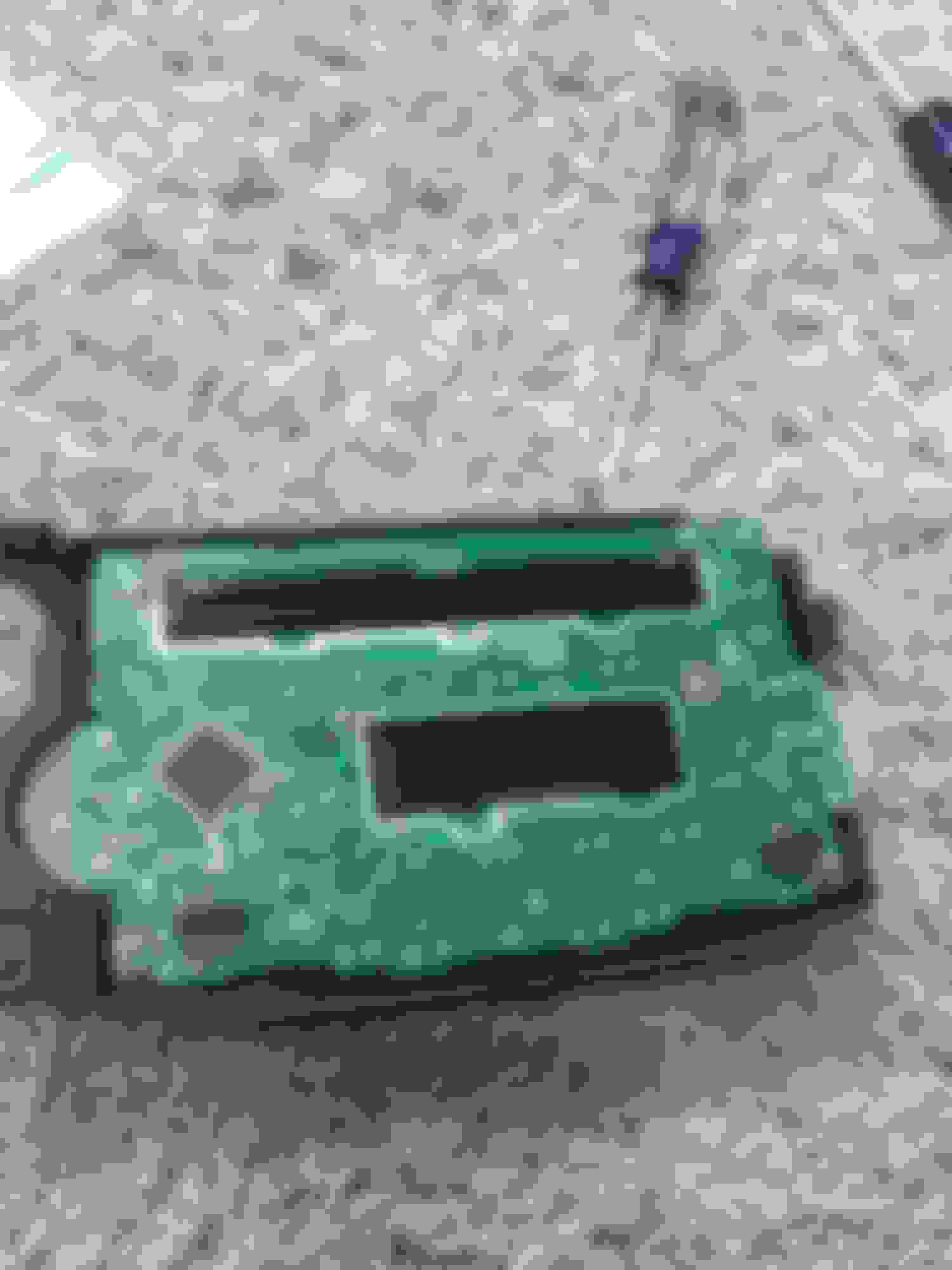
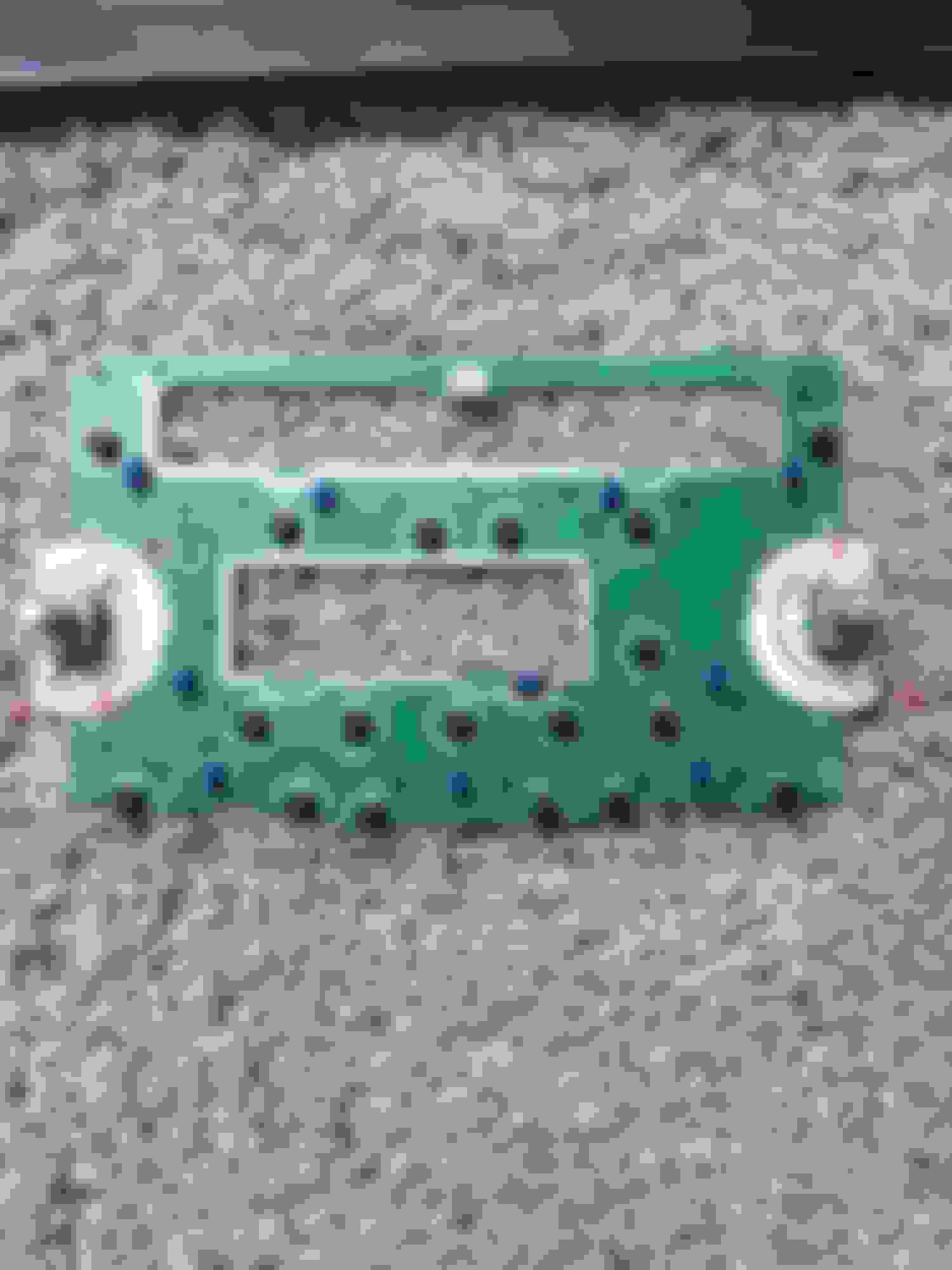
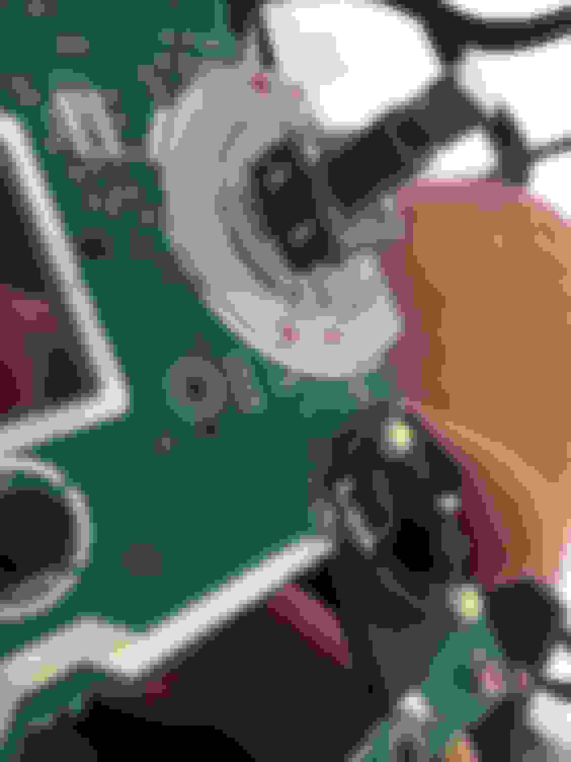
Here is what you should see after the circuit board has been fully removed from the face of the radio:
As you can see, I made a few markings on the circuit board with a Sharpie. I labeled the positive and negative terminals of each bulb location. The polarity is important to note, because you will have to match up the polarity of the new LEDs to the polarity of the solder points on the circuit board.
You may also notice a few additional Sharpie markings on the circuit board. These dots represent where I had originally planned to install the new LEDs. Most LEDs have forward illuminating lights, unlike the OEM bulbs that dispurse light in more of an outward fashion. Basically, each button on the radio should have their own corresponding LED to avoid having hotspots. Because of this, each exsisting soldering point will have multiple LED legs connected to it. You’ll see what I’m talking about in just a little bit. Hang tight.
Step 3: Remove OEM Bulbs
Because you are replacing the old OEM bulbs with new LEDs, you will need de-solder the pre-existing bulbs from the circiut board first. Each bulb is attached to the circuit board at two solder points (one positive and one negative).
Simply use your soldering iron to heat up the soldering point on one side of the bulb. Once you can see that the metal has become liquified, with your tweasers, pull the edge of the bulb upwards to release the bulb from the circuit board. If done correctly, one side of the bulb will be detached. Repeat this process for the other side of the bulb and continue to do so until all of the OEM bulbs are removed.
Step 4: Prepare LEDs
By this step, you sould have your circuit board detached, clear of all OEM bulbs, and ready for the new LEDs. However, before you can start soldering your new LEDs to the circcuit board, you need to make sure that your new LEDs are properly prepared.
As stated previously, in order for this modification to be completed properly (i.e. to avoid hot spots), multiple LEDs need to be soldered to each pre-existing solder points, so that the new LEDs can illuminate each button individually. Therefore, you will have to unwind the legs of each LED from the housings and lengthen them with a wire of your choice. I used some spare copper wire I had laying around and soldered it to the legs of my LEDs to lengthen them. Step 5: Soldering/Fitting the LEDs onto the Circuit Board
Here is where you will begin to solder the new LEDS to the circuit board This is by far the most time consuming and frustrating process. I would guess that this step alone took me nearly 8-10 hours to complete. This is still fun right? Gosh, I was about the throw this thing in the trash.
You have to remember that the location of the new LEDS will not line up with where the pre-existing OEM bulbs went. Therefore, your patience will be tested. You have to worry about “fitting” the LEDs in the correct location as well as making sure that you have continuity between all of your LEDs.
*If you look closely, you'll see that in the second image I had to solder the radio knob LEDs to the other soldering points. While attempting to solder my new LEDs into place , I got the contact points too hot and melted the copper linings on the circuit board. Therefore, I had to solder them to a new/different contact point.
After I soldered all of my LEDs to the circuit board, I tried screwing it back together, attaching it to the face of the radio. It went together roughly, but I couldn’t hardly push any of the buttons “down”. The new LEDs were prohibiting the buttons from working properly, because the LED was getting in the way.
The physical buttons are attached to the circuit board itself. The part that you can see on the face of the radio is simply a button cap. In between circiut board button and the button cap is a clear plastic diffuser. When you push down on the button cap (the part that you see on the face of the radio), it pushes down on the spring-loaded button, which is attached to the circuit board. However, if an LED is keeping the plastic diffuser from reaching the button properly, the button won’t work. It’s hitting the LED instead, which is likely in the way.
I wish I had a picture of what I’m talking about. Unfortunatley, I don’t. If you work on this modification, you’ll quicly realize the frustations I, and many others, experienced.
After countless hours of trial and error, I gave up. I got out my Dremel and went to town on some of the plastic diffusers. If the LED was hitting the clear plastic diffuser, I slowly, yet carefully, ground down the clear plastic diffuser with my Dremel attachments. Grinding down the clear diffuser made it so that the LED could fit properly behind the face of the radio. Again, I seriously wish I had a picture of this. If you need help, don’t hesitate to post in this thread or PM me directly.
Step 6: Testing the Circuit Board
Once you get the buttons working properly, it’s time to test the circuit board. I didn’t have a “safe” way of testing the circuit board without installing it back into my car. Therefore, I just took apart my dash to test it, which didn’t matter as I was going to re-install the new circuit baord anyways.
After my first try, I think all but 4 LEDs lit up on the circuit board. I took the radio back apart and quickly found that two of my LEDs were touching and the continutiy was broken. A little more electrical tape and I was good to go.
Step 7: Have a Beer
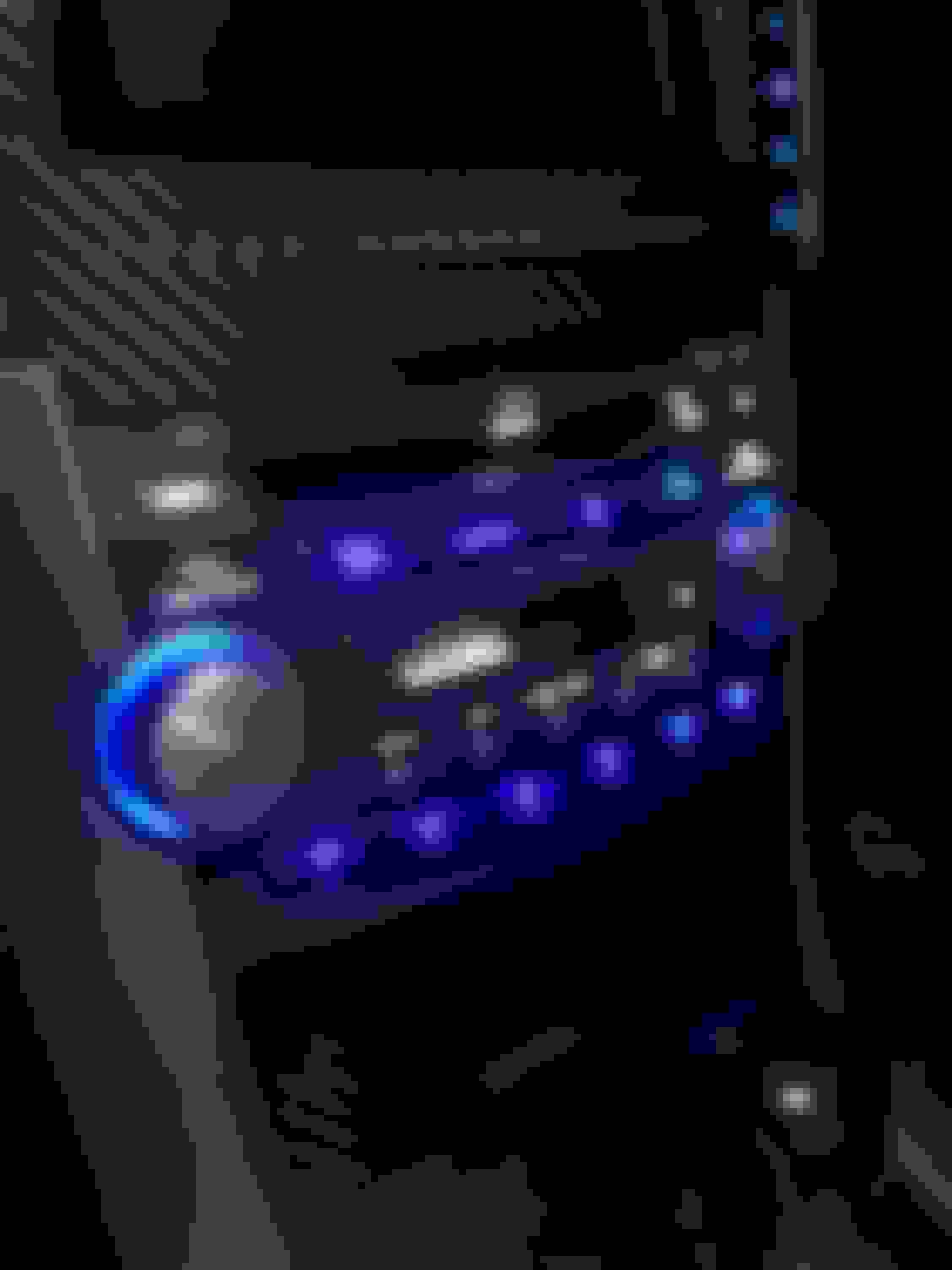
If you’ve made it this far, congratulations. This project is no easy task by any means. However, I always find it intriguing to challenge myself in new ways. Here are my final results:
You may notice that I have other areas where I upgraded to LEDs as well, including the Climate Control/HVAC unit, Seat Heaters, and the Shifter. I’ll write separate threads for these as well. There’s a quick an easy way to upgrade these areas, then there’s the “right” way
While I had my car torn apart, I also completed some carbon fiber modifications as well. I can write a DIY for this as well. I took some pictures along the way, so just let me know if you’re interested.
I just replaced all my climate control and navi lights with LEDs and this was perfect timing. Gonna find a TL being parted and pick up a spare radio to follow your lead. Thank you!
It's rare how the lights in the radio went out. Never had any go out in my 2 TLs but plently of other t3 neo bulbs go out.
Yeah, it was super annoying. When I bought the car back in 2015, only a few of them were working.
Originally Posted by lovic87
I just replaced all my climate control and navi lights with LEDs and this was perfect timing. Gonna find a TL being parted and pick up a spare radio to follow your lead. Thank you!
That sounds like a solid plan. Let me know if you have any questions. Try checking eBay too. You may be able to find one that is reasonably priced.
The solder job makes me cringe, but hey it works!!! Good job and nice DIY. Always hated that in my old TL. Never made sense why they did that from factory....
If only you knew how many times I had to change it after my initial modification. By the end, I was like "F-it!!! I'm doing whatever works at this point."
I don't have any issues while driving at night. They are definitely bright, but it's never in my field of vision, so it hasn't been a problem. Additionally, I'm sure that my iPhone 6 camera isn't capturing the best quality. If you're worried about the brightness, you can always buy LEDS where you have to add your own resisters. Just use resisters with a higher rating.
I have heard that some people have experienced issues when they replace the bulbs with bright LEDs on the steering wheel though. This would be more of an issue as the bulbs are shining directly towards your field of vision.
Op
Nice writeup. Try taking photos when you manually decrease brightness, it usually works better. Or just shot from further away.
I did this a while ago as well. I used some SMD LEDs and SMD resistors (replacing ones on the rear of the panel). Looks nice but I have some darker and lighter spots.
And you're allowed to brag. Your tablet install is turned out awesome. I'm in the process of researching and gathering supplies myself. I've bookmarked your thread for reference (along with many others).
Now that I installed carbon fiber on the storage compartments, I'm trying to figure out the best/cleanest way to maintain them and not relocate the display down below.
They do, but only a little bit. You can see real difference only when you switch between max and min.
Because of that select resistors for brightness that you want
Exactly... they the only real differences occur between the maximum and minimum brightness. When you switch to minimum brightness, things like the radio/hvac display and your speedometer areas can become difficult to see.
Thank you for posting this! I have been also on the fence about doing this to my radio also and this will help tremendously. What tablet did you have installed by the way?
What you are experiencing was definitely a huge concern of mine before I started this process.
A lot of SMD-style LEDs are front facing, meaning they don't shine outwards. If you install LEDs and only use the original bulb locations, the LEDs will likely not shine into all buttons/crevices of the radio, causing what are called "hot spots.". The stock bulbs have more of an outward light pattern and that is why the entire radio display will light up green (or red for TL-S radios) if all stock bulbs are functioning.
Therefore, many people who complete this conversion will add additional bulbs (pretty much one LED per button) so that all buttons will be illuminated. Keep in mind that adding additional LEDs can (and will) interfere with how the circuit board is seated into the face of the radio. You have to place each LED on the circuit board VERY carefully in order for everything to fit back together well. This takes a lot of trial and error.
The reason I added electrical tape underneath each LED is because there are so many copper lines on the circuit board that disrupt the continuity of the bulbs circuit. I had several instances where an LED leg was touching a small piece of metal and the bulb would not light up. While soldering, I always made sure to test for continuity to make sure that no legs of the LEDs were touching each other or other metal components on the circuit board. I had one pesky bulb that kept flickering on/off and I had to take apart the radio and redo the soldering and electrical tape maybe 4 or 5 times. It kept touching the metal around the tape player if I remember correctly.
Did anyone get a picture of the back of this board?
On the Homelink board, there are zero value resistors in series with the bulbs. This would indicate LEDs may have been intended at some phase of the design process. I'm wondering if the situation with the head unit is similar.
Did anyone get a picture of the back of this board?
On the Homelink board, there are zero value resistors in series with the bulbs. This would indicate LEDs may have been intended at some phase of the design process. I'm wondering if the situation with the head unit is similar.
Don't judge too much, it was my first approach.
Yes there are factory low value resistors on the back in series with every bulb. Later I bought SMD resistors and SMD LEDs. Makes it much cleaner and much simpler mod. And if you use SMD LEDs, they are sitting closer to the board, so you don't need to add extra LEDs to have even light coverage.
Did anyone get a picture of the back of this board?
On the Homelink board, there are zero value resistors in series with the bulbs. This would indicate LEDs may have been intended at some phase of the design process. I'm wondering if the situation with the head unit is similar.
Just FYI- There is also a picture of the back of this board in my original post where I show the screws that need to be removed.
Originally Posted by peter6
Don't judge too much, it was my first approach.
Yes there are factory low value resistors on the back in series with every bulb. Later I bought SMD resistors and SMD LEDs. Makes it much cleaner and much simpler mod. And if you use SMD LEDs, they are sitting closer to the board, so you don't need to add extra LEDs to have even light coverage.
Hmm... I may have to disagree with you on this . I also used SMD LEDs, but still found hot spots occurred when only replacing the factory bulbs in their original locations. The light output of my LEDs may be more narrow than yours? However, the board sits so close to the face of the radio that getting even light coverage for all buttons was difficult. I don't remember who, but I saw a post of someone else who completed this modification and posted pictures of each method and why he changed it. If I can find the pictures, I'll share.
Well, doesn't the Homelink board already have two LEDs for the two blue lights? Could that why there are resistors?
Yeah, this is separate. There are LEDs with their own series resistors for the map lights, but there are also zero value resistors in series with the bulbs for the Homelink buttons. I was able to swap the SMD resistors for 5.1k and the incandescent bulbs for through-hole LEDs:
Hmm... I may have to disagree with you on this . I also used SMD LEDs, but still found hot spots occurred when only replacing the factory bulbs in their original locations. The light output of my LEDs may be more narrow than yours? However, the board sits so close to the face of the radio that getting even light coverage for all buttons was difficult. I don't remember who, but I saw a post of someone else who completed this modification and posted pictures of each method and why he changed it. If I can find the pictures, I'll share.
I missed that you used SMDs. The only difference I can see now is that I used "clean" SMD LEDs, without the "base" like you did, so they may actually sit slightly closer.
That's why I also needed to replace resistors on the back - my LEDs don't have resistors build-in.
The ones I ordered are:
I guess that is the problem with every DIY modification. Hundred ways, hundred different parts, and even more opinions. And then even if you order same stuff as me, you might receive different parts.
Anyways, if you find that thread if would be great to compare.
I did a full LED conversion on my old TL. Now on my new one, I stick with the OEM because it has a nicer subtle glow and doesn't hurt the eyes at night! The brightness at night will get to you.
So finished this up. The light switch itself was a bit tricky since I am using the T3 wedge LEDs. I removed the plastic base on the wedge and bent the leads to point the COB end towards the front. A little flux on the solder points kept it in place.
Also removed the blue T3 wedge bases and soldered directly onto the board for the HL buttons.
The dome lights were easy 5 point 194 wedges. We'll see if they are bright enough. I did put this same wedge modified into a T5 base for the shifter and it's working very well. Here's the link to those 194s:

 09-03-2017, 07:27 PM