
DIY: Grounding Kit
 07-23-2012, 04:05 PM
#1
Ah, hamburgers!
Thread Starter
DIY: Grounding Kit
This is a DIY that is popular among the DIY crowd but not many here have explored into the notion of a DIY grounding kit.
The logic is simple: provide a consistent linear grounding plane between the engine and chassis. With today's cars, there are immense amount of sensors, electronics, etc. floating around the engine bay. They all require a good grounding point to function to spec and this DIY provides a adequate engine-chassis ground reference.
I examined the engine compartment for the grounding points and came up with four important locations. What needs to be addressed here is the alternator, any sensor mounted to the motor, the transmission casing, and the throttle body. I basically daisy chained from one point to the other.
What is needed:
4 AWG power wire
4 AWG terminals
Heat shrink
Electrical tape
Teflon tape
Total amount spent was less than $20.
How I did it:
First you want to take some kind of measuring tool (rope, hose, etc) to measure out the distances between the points. Then cut, terminate, and heat shrink the wire for a finished product. For a extra step of reliability, I Teflon wrapped and taped the lengths which will be hovering around the engine area to keep it from melting.
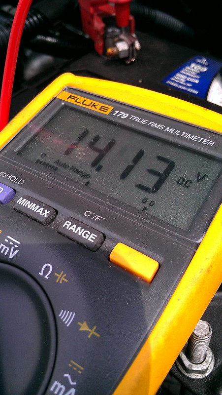
To begin, I measured the voltage across the battery with the car running just to see if there would be a difference. It fluctuated between 14.11-14.13V.
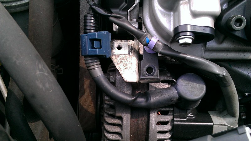
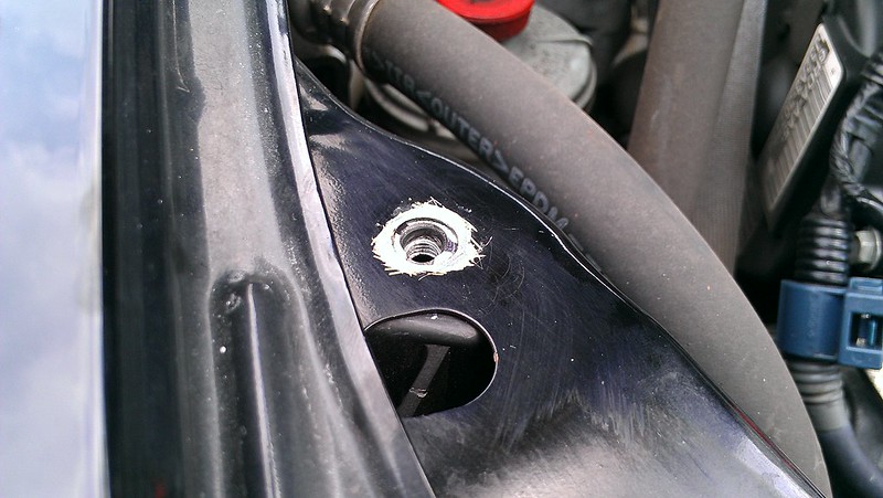
To get started, the alternator casing was grounded to the chassis. I removed the bolt on the chassis nearest to the casing. I wanted to keep this ground wire as short as possible as this is the main generator of power. For each point of ground, you want to make sure that each surface to be mounted is to be sanded down to bare metal for maximum contact.
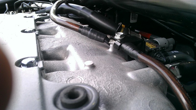
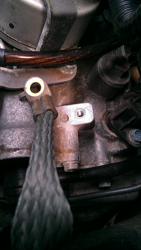
Then this point was daisy chained to the sensor in the middle of the rear of the IM.
Then it was forwarded to the stock grounding location on the transmisson casing.
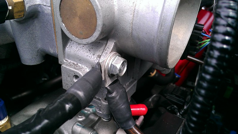
Then it goes to the lower bolt of the throttle body..
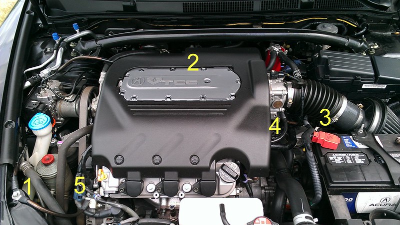
..where it returns to the alternator casing to finish the grounding "star".
Here you can see the five points which form the star.
When I measured the voltage again, to my surprise, it read a steady 14.18V.

So I took it for a drive and could immediately tell that the throttle response was improved, the gear shift (I have a auto) was lessened, and the car felt smoother throughout the range. It's not a night and day difference but definitely noticeable.
To further enhance this mod, I will be doing a Big 3 soon which should help with any type of issues associated with voltage drain.
To conclude, I say this is more than worth it. It's as easy a pie.
The logic is simple: provide a consistent linear grounding plane between the engine and chassis. With today's cars, there are immense amount of sensors, electronics, etc. floating around the engine bay. They all require a good grounding point to function to spec and this DIY provides a adequate engine-chassis ground reference.
I examined the engine compartment for the grounding points and came up with four important locations. What needs to be addressed here is the alternator, any sensor mounted to the motor, the transmission casing, and the throttle body. I basically daisy chained from one point to the other.
What is needed:
4 AWG power wire
4 AWG terminals
Heat shrink
Electrical tape
Teflon tape
Total amount spent was less than $20.
How I did it:
First you want to take some kind of measuring tool (rope, hose, etc) to measure out the distances between the points. Then cut, terminate, and heat shrink the wire for a finished product. For a extra step of reliability, I Teflon wrapped and taped the lengths which will be hovering around the engine area to keep it from melting.
To begin, I measured the voltage across the battery with the car running just to see if there would be a difference. It fluctuated between 14.11-14.13V.
To get started, the alternator casing was grounded to the chassis. I removed the bolt on the chassis nearest to the casing. I wanted to keep this ground wire as short as possible as this is the main generator of power. For each point of ground, you want to make sure that each surface to be mounted is to be sanded down to bare metal for maximum contact.
Then this point was daisy chained to the sensor in the middle of the rear of the IM.
Then it was forwarded to the stock grounding location on the transmisson casing.
Then it goes to the lower bolt of the throttle body..
..where it returns to the alternator casing to finish the grounding "star".
Here you can see the five points which form the star.
When I measured the voltage again, to my surprise, it read a steady 14.18V.
So I took it for a drive and could immediately tell that the throttle response was improved, the gear shift (I have a auto) was lessened, and the car felt smoother throughout the range. It's not a night and day difference but definitely noticeable.
To further enhance this mod, I will be doing a Big 3 soon which should help with any type of issues associated with voltage drain.
To conclude, I say this is more than worth it. It's as easy a pie.
Last edited by jiggad369; 07-23-2012 at 04:19 PM.

The following users liked this post:
Undying Dreams (07-23-2012)
07-23-2012, 04:20 PM
#3
Ah, hamburgers!
Thread Starter
 07-23-2012, 04:22 PM
#4
Suzuka Master
https://acurazine.com/forums/3g-tl-photograph-gallery-96/hyper-voltage-grounding-kit-install-606115/
Similar concept with sun system integrated but you dont need to use the device.
Similar concept with sun system integrated but you dont need to use the device.
07-23-2012, 04:24 PM
#5
Ah, hamburgers!
Thread Starter
https://acurazine.com/forums/showthread.php?t=606115
Similar concept with sun system integrated but you dont need to use the device.
Similar concept with sun system integrated but you dont need to use the device.
 anyways!
07-23-2012, 04:53 PM
anyways!
07-23-2012, 04:53 PM
#7
Ah, hamburgers!
Thread Starter
I had some cheap wire from a previous install laying around and I got the terminals from a local electrical shop.
but no I did not remove any stock ground points.
but no I did not remove any stock ground points.
Trending Topics
07-23-2012, 05:43 PM
#10
Suzuka Master
Battery supply stores will have cables of various lengths premade with terminations
07-23-2012, 08:28 PM
#12
Sorry but i'm not buying it. How can you prove that the immediate throttle response, "gear shift was lessened", and "car felt smoother throughout the range" wasn't caused by the ECU resetting itself after being disconnected from source voltage for said amount of time?
07-23-2012, 08:31 PM
#13
Ah, hamburgers!
Thread Starter
Sorry but i'm not buying it. How can you prove that the immediate throttle response, "gear shift was lessened", and "car felt smoother throughout the range" wasn't caused by the ECU resetting itself after being disconnected from source voltage for said amount of time?
For $20, you have nothing to lose while keeping all the sensors and electronics happy.
07-23-2012, 09:13 PM
#14
Three Wheelin'
When the Op says what he is saying, I tottaly believe him. And as i said that is also my next project as I think it will add to what the battery fixed and make it that much better.
07-23-2012, 09:20 PM
#15
Ah, hamburgers!
Thread Starter
Stable voltage, at least in my experience make a world difference in this car. Myself and "Ihatecars" had major throttle surging issues and slugish performance until he replaced the battery and i followed. Thanks to him we dont have that problem anymore. We both had optima batteries and now we have the Sears Die Hard Platinum, very expensive battery but worth every penny.
When the Op says what he is saying, I tottaly believe him. And as i said that is also my next project as I think it will add to what the battery fixed and make it that much better.
When the Op says what he is saying, I tottaly believe him. And as i said that is also my next project as I think it will add to what the battery fixed and make it that much better.
12-06-2012, 07:46 PM
#16

did you connect throttle body back to the alternator casing with the 4gauge or are they just "connected" because they're one big chunk of metal?
 12-09-2012, 05:36 PM
#19
Suzuka Master
Warranty voiding for additional grounding! Too scary
12-09-2012, 07:15 PM
#20
Engineer in Training
You can, and unless they can prove IN WRITING how it caused any issue DIRECTLY related to the problem they're using to void your warranty you have nothing to worry about. Look up the Magnason Moss Warranty Act: http://en.wikipedia.org/wiki/Magnuson�Moss_Warranty_Act
12-10-2012, 07:00 AM
#22
'07 TL Type-S
Thanks for the write up.
Did this on my Maxima last year and never got around to doing it on my TL. It'll be my next project for the future.
Did this on my Maxima last year and never got around to doing it on my TL. It'll be my next project for the future.
12-10-2012, 09:04 AM
#23
My first ricer
iTrader: (4)
By any chance did you measure each piece of wire you cut? I'd like to do this mod as I've done wiring upgrades to my Impala and my last DD Trailblazer SS. On the Imp SS there was a guy who made a kit that replaced all the battery cables with 1/0 wires. For my TBSS I had a kit that was 4 gauge and ran next to the battery cables and had a few extra grounds.
Maybe I'm brain dead and missed it, did you run an extra wire positive to alternator? I know you didn't call it a big 3, but I'm sure it's gotta be worth adding.
Maybe I'm brain dead and missed it, did you run an extra wire positive to alternator? I know you didn't call it a big 3, but I'm sure it's gotta be worth adding.
 04-04-2014, 08:45 AM
#26
My first ricer
iTrader: (4)
Do it! It's easy, I just used some extra 4 gauge from an old amp install kit, you could buy a few feet of if for a few dollars and 10 or so 4 gauge ring terminals, dirt cheap. I know this thread is just grounding, but it's easy to add an extra hot wire, basically do the same thing but between the battery and alternator, add an inline fuse for safety since it's a positive wire. I just ran it next to the factory one. Never had a light dim when my 12's are pounding and my idle is nice and smooth.

Thread
Thread Starter
Forum
Replies
Last Post
MrHeeltoe
1G TSX Tires, Wheels, & Suspension
20
02-23-2023 01:54 PM
MrHeeltoe
2G TSX Tires, Wheels & Suspension
3
09-29-2015 10:43 PM
MrHeeltoe
3G TL Tires, Wheels & Suspension
0
09-28-2015 05:43 PM

