E-010: DIY: Power Folding Mirrors
 05-26-2014, 12:26 PM
#1
Racer
Thread Starter
E-010: DIY: Power Folding Mirrors
At last, after countless hours of research and man hours, I was able to convert my USDM mirror to have the PFM function. This function is helpful because it helps me enter tight spaces w/o having to manually push in my mirrors. Also, it’s a cool feature to have overall.
Background:
I was trying to get the set up to be as OEM as possible using the OEM PFM switch but I’ve exhausted all my efforts and couldn’t get the mirrors to fold/unfold using the OEM switch (SEE THREAD: https://acurazine.com/forums/2g-rl-2005-2012-76/where-purchase-oem-parts-overseas-904690/).
I decided to do some more research and ended up drawing my own wiring diagram and creating my wiring harness based off my diagram. I ended up getting it to work with some relays and an aftermarket switch.
You would still need to get the 11-12 RL Advance mirrors ($920) or mirror actuator ($230- the money saving way) to do this conversion. I opted to go with the mirror actuator route since I’m pretty handy.
Before beginning the DIY, be sure to read the entire guide before proceeding. This was written for reference, use the information contained within at your own risk.
Parts/supplies needed:
� R, PFM actuator - #76211-SJA-A11
� L, PFM actuator - #76216-SJA-A11
� x2 SPDT relays
http://www.autozone.com/autozone/parts/_/N-9cikb?itemIdentifier=297371_0_0_
� SPDT On-Off-On toggle/rocker switch
� Add –A-Fuse (ATM)
http://www.autozone.com/autozone/acc...entifier=32416
� In-line fuse (ATM)
http://www.autozone.com/autozone/acc...ier=32420_0_0_
� 10 amp ATM & 5 amp ATM fuse
� Crimping plugs
� Various size terminal connectors
� Male & female wire connectors
� Electrical tape & painters tape
� Electrical wire router (I used a long zip tie)
� Unwind metal clothes hanger
� x2 16-18 AWG wire (Black & Red)
� Wire stripper
� Wire looms (optional)
� Variety phillips/flat head screwdriver
� Torx screw size 20
� Trim removal kit
� 10 MM socket & drive
� Razor blade
In total (minus the research), I spent a total of about 12 hours in a span of a few weeks on this project. I would rate this DIY about a 5/10 in difficulty. The most difficult part is removing the mirrors and routing the wire. A major amount of time was spent on getting the mirrors to fold/unfold with the OEM switch. If I were to do it again, it would take me about 3-4 hours max. Total I spent to do this conversion came out to $300.
PROCESS:
Before disconnecting the battery be certain you have the radio/navi code, both mirrors adjusted in the upward position.
Disconnect the battery:
Remove the negative terminal and put aside in a shop towel
Remove the driver’s door panel:
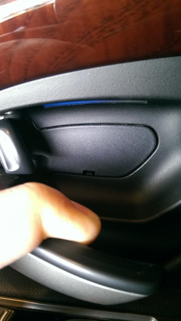
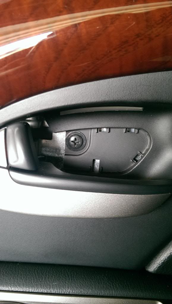
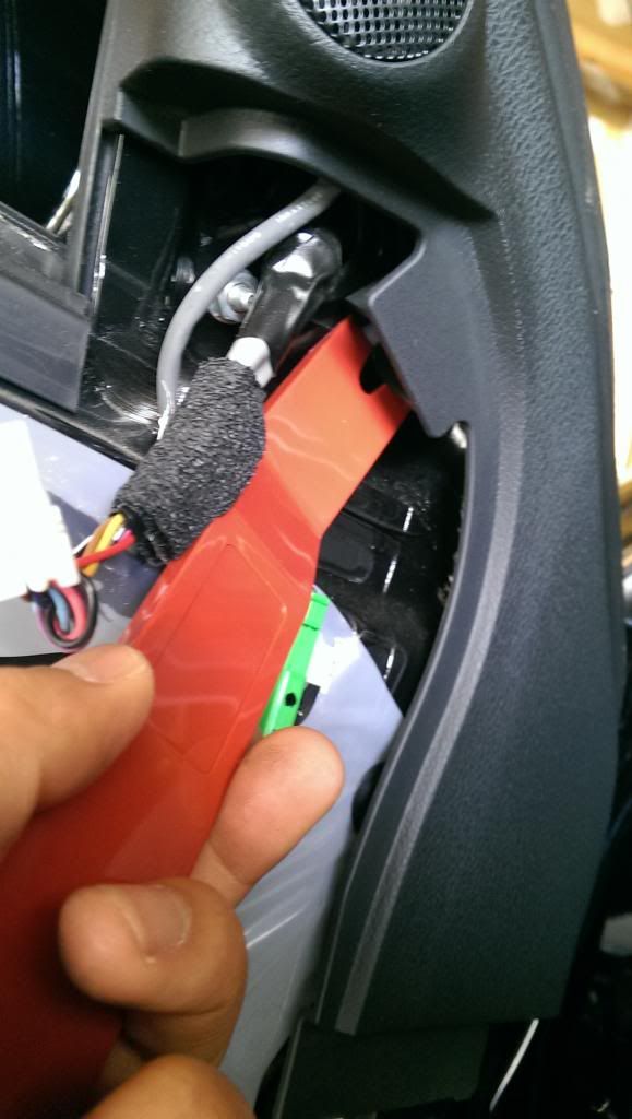
Remove inner release handle cover. (I applied masking tape over the tip of the flathead to prevent scratches). Push up on clip w/ flathead and use another flathead and pry out from the left side. Remove screw
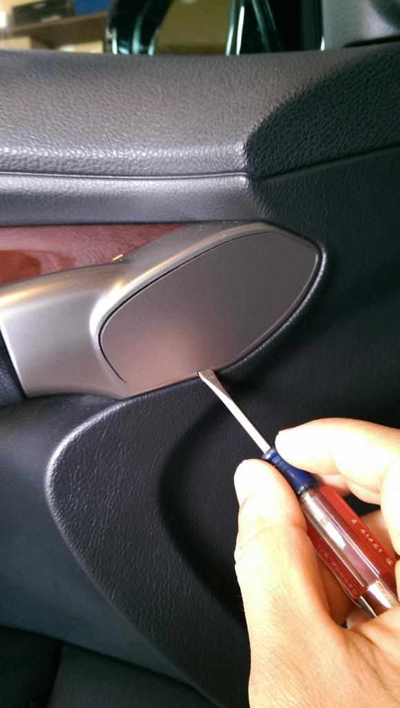
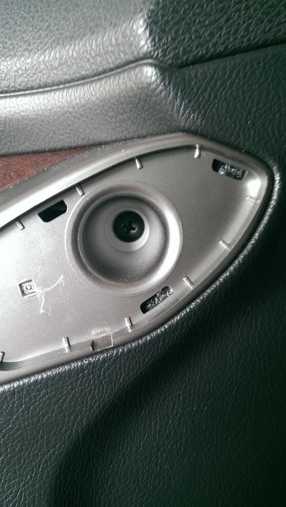
Remove inner door handle cover w/ a thin flathead. Place thin flathead in slot and pry outwards and remove screw
Remove the door light cover. Use a trim removal tool and insert on top and pry downwards. Remove screw
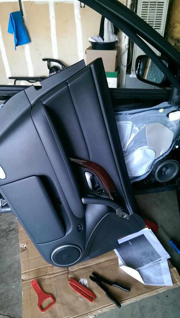
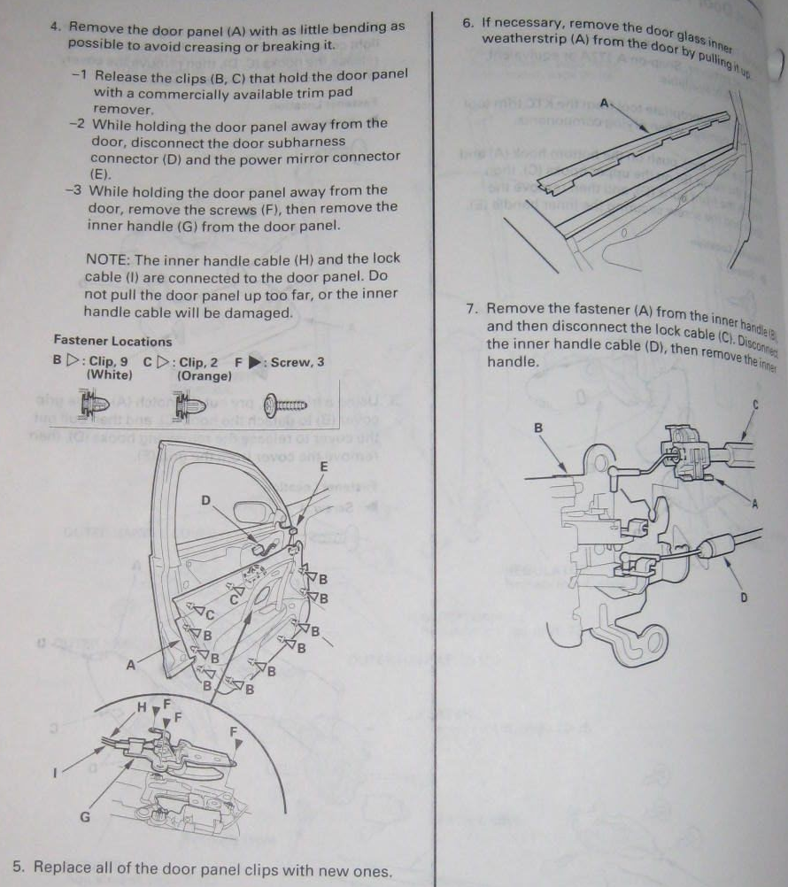
To remove the door panel from the door shell, start by pulling out the upper right corner of the panel and work your way clockwise. (Use a trim removal kit to help release clips). There are two orange clip on the upper left side and upper middle. After all bottom clips have been removed, tuck your hand in and gently pull out the panel. The door panel is held by clips. Use the trim kit to remove any stuck clips on the door shell and re-attach to the door panel.
Disconnect mirror connector and driver’s main control unit. Take caution of the door handle rod and lock rod. (There is no need to remove rod). Just flip the door panel as shown
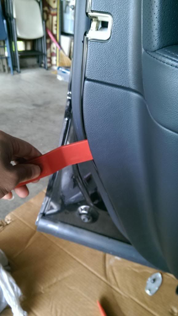
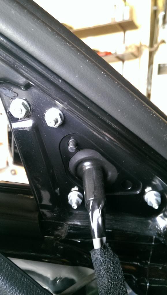
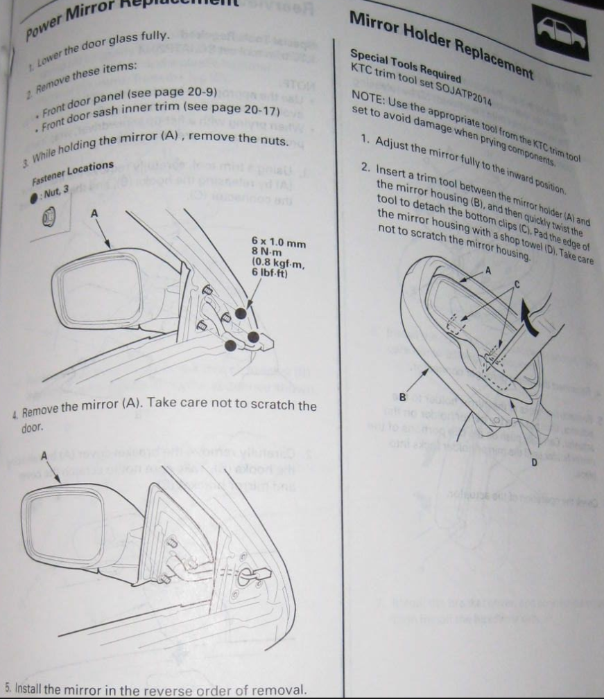
In order to remove the mirror you will first need to remove the upper door sill trim. Using a trim remover tool, remove the upper and lower clips and gentle pull outwards until you have access to the 3 mirror screws.
Remove the driver’s mirror:
Using a 10mm socket, remove the x3 screws (hold the mirror while removing screws).

Here's the PDF for reference:

Disassemble mirror:
Mask up mirror w/ masking tape to prevent scratches (Don’t mask up where the outer and inner mirror shell connects)
To remove the mirror, use an angle trim removal tool and insert the tool between the mirror and mirror base and pry left and right to pop out the two bottom latches (one on each side). Unhook the mirror from mirror base and disconnect the two black mirror defogger wires.

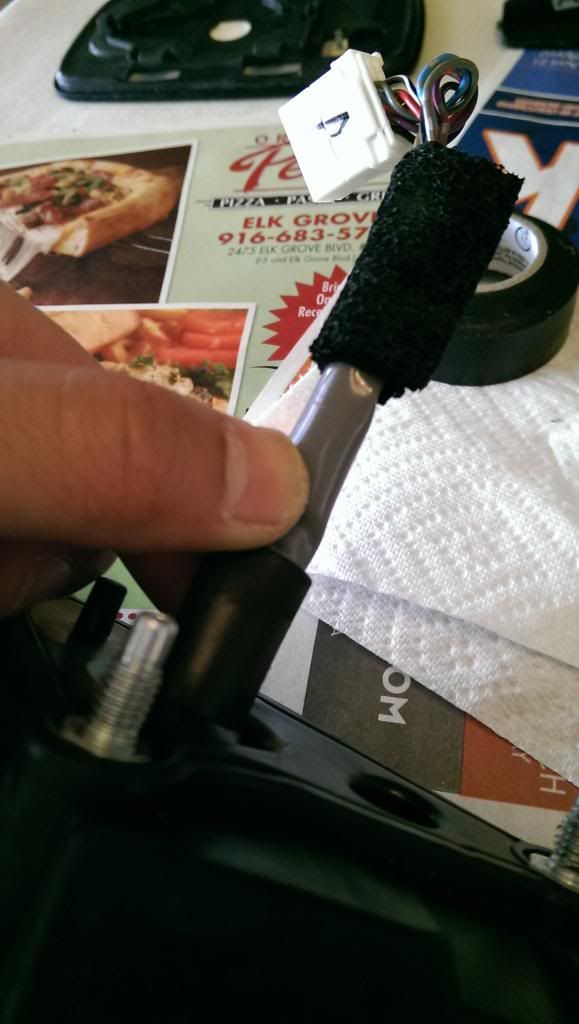
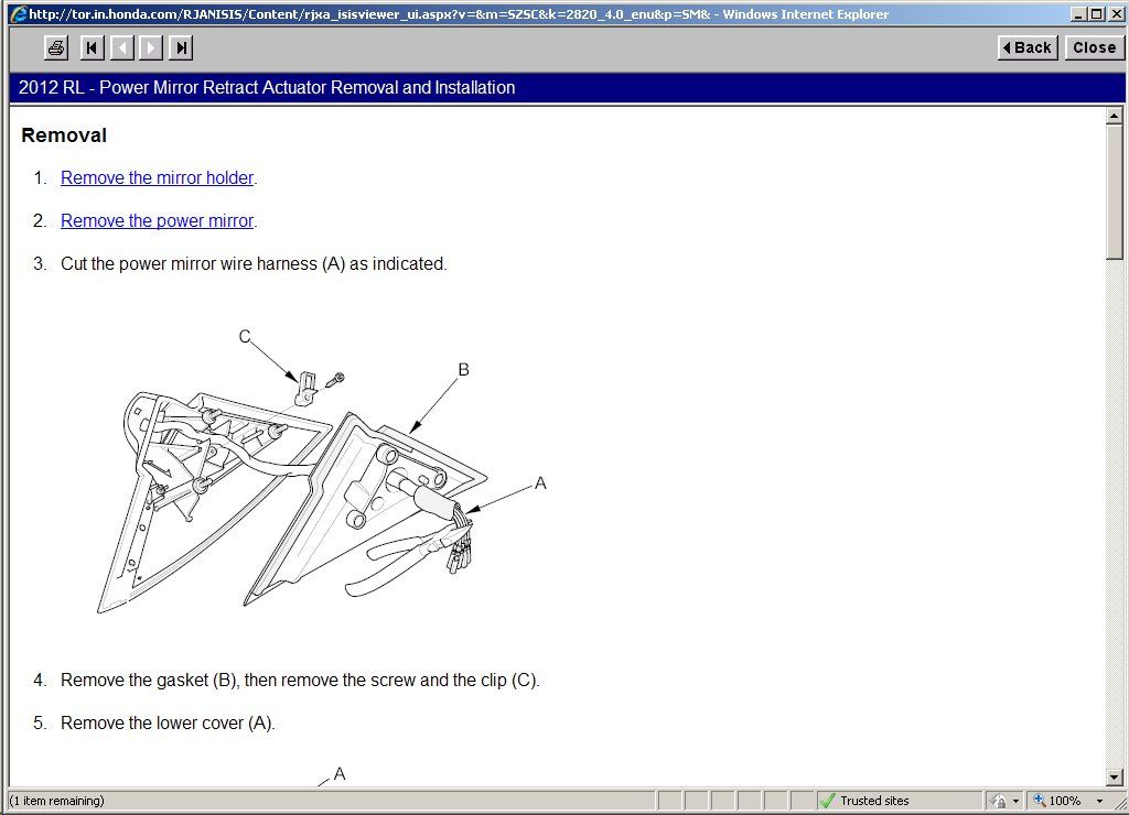
The original harness will need to be cut to complete the assembly. Cut the harness at the section where the foam tape ends toward gasket (A new harness will come w/ the actuator)
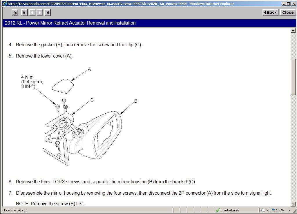
Use a thin flat head and insert into bottom cover and pry to the left. Use a torx socket and remove x3 torx screws (new screws will be provided).

 Remove mirror gasket then removed the harness tie down clip and remove the mirror base from the mirror while routing the wires through the slots (take note of how mirror harness is routed and the position of wires etc)
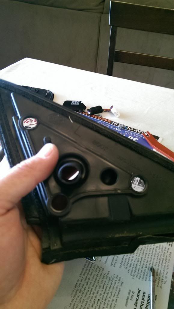
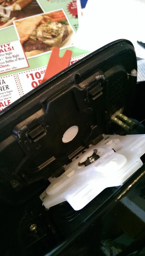
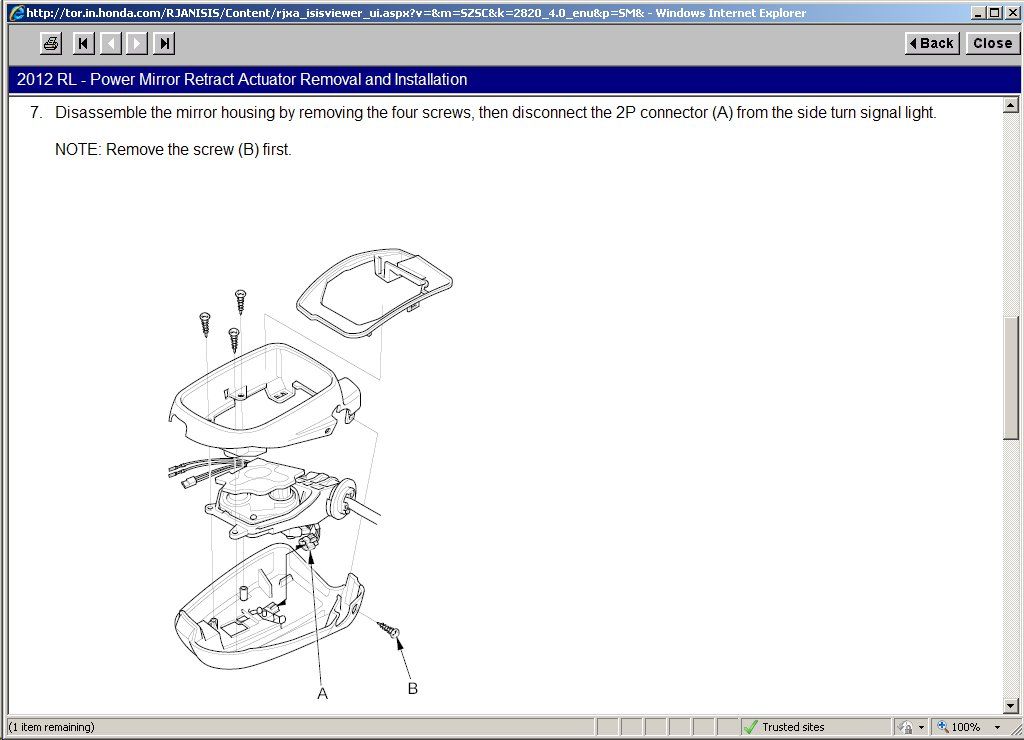
The mirror shell will need to be removed in order to remove the mirror actuator housing. You have to be really gentle on the removal process as the clips break really easy. Remove the 5 circled screws as shown (don’t remove the x3 mirror actuator screws until the mirror base is apart).
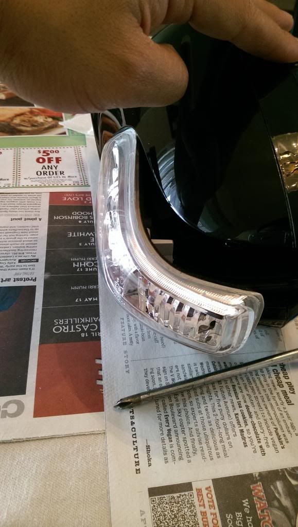
Remove the turn indicator by popping it out and sliding it towards the right and remove the connector.
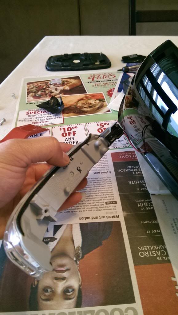
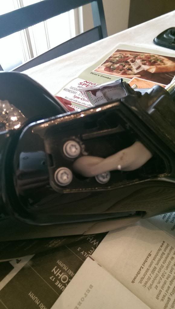
After the x5 screws have been removed, begin w/ the upper right clip as shown on picture. Put flathead in clip and push in while carefully pulling mirror shell outwards. Another clip will be on the bottom below mirror actuator housing. Use flathead and push on clip while carefully pulling mirror shell outwards. The last clip will be on the inside towards the right. Use a long flathead and push on clip while carefully pulling mirror shell apart.

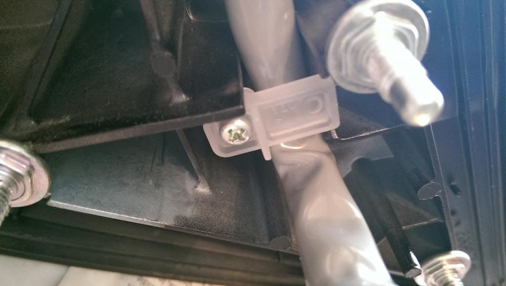
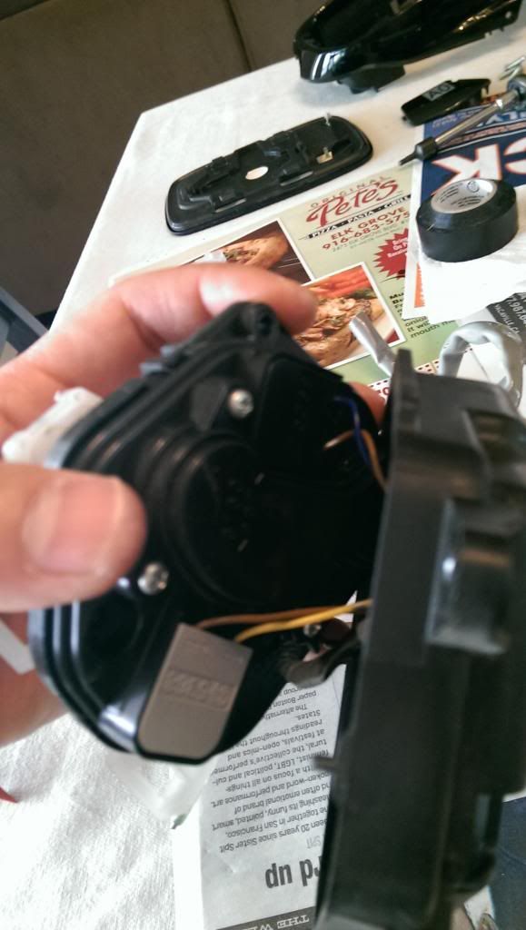
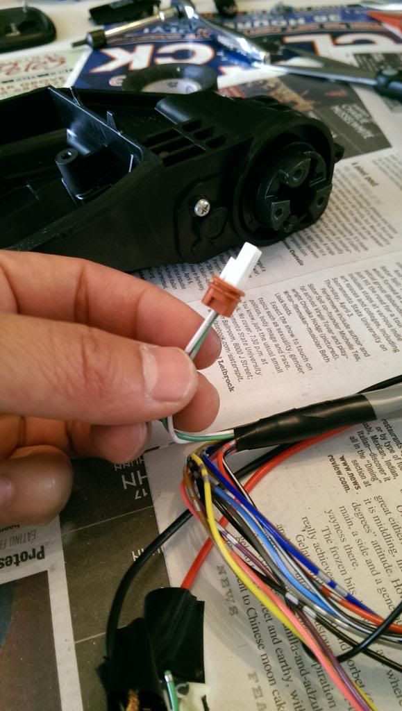
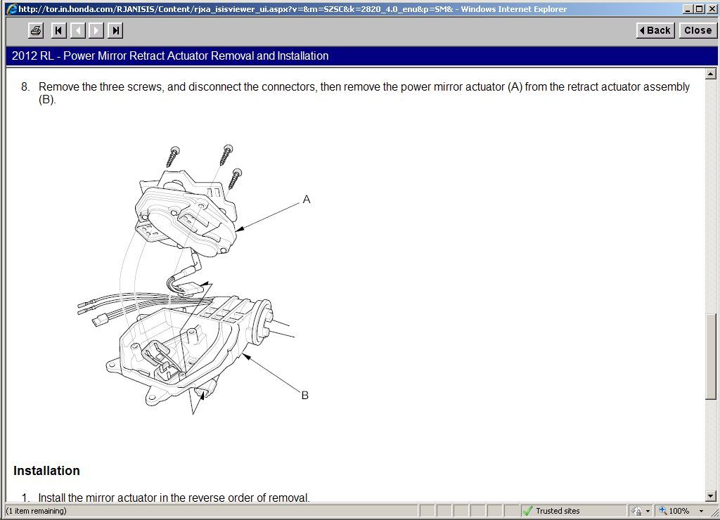
Remove the three screws and on the mirror actuator. Disconnect the connectors (black & gray) by pulling upwards starting from the bottom. To remove the harness connector, you will need to remove the white clip then you can disconnect the connector.
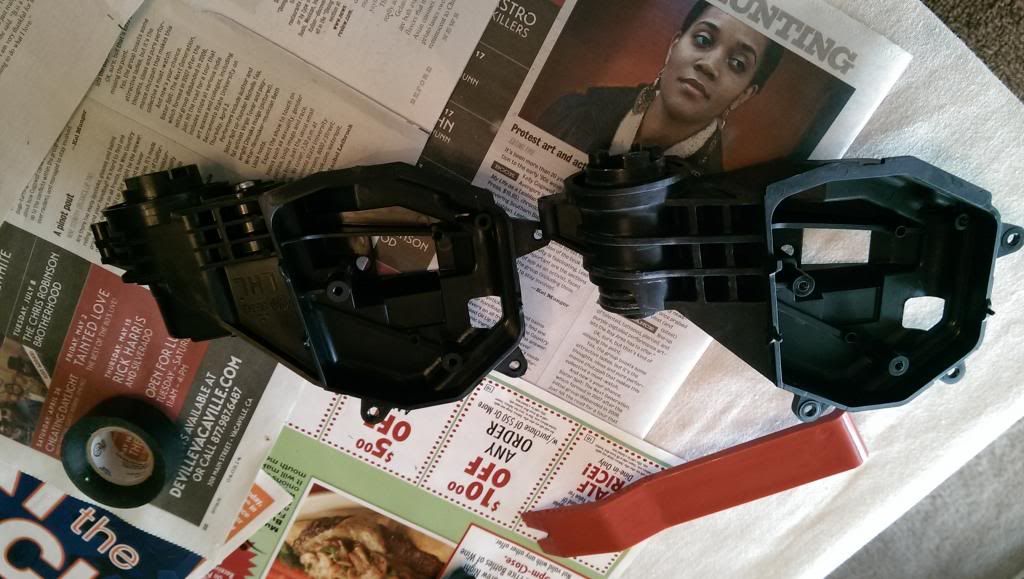
Notice that the components are different between the PFM turn actuator and the non PFM turn actuator
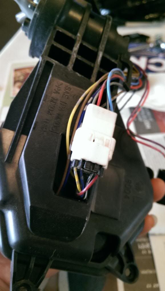
Notice the two extra wires absent on the other harness. The brown connector will be inserted into the turn actuator.
Reinstall the mirror components in reversal of disassembly (Be sure everything is connected properly and do not put the wires back into the connector yet until everything is fully assembled)
Mirror removal instructions:

Note: The two black defogger wires can go into any slot on the mirror as they end up being one wire. Also put the foam tape in the same location as it was on the original harness
Using the picture below, insert the pins using the location as shown. Leave the white and green wire as is as the wires will be routed separately.
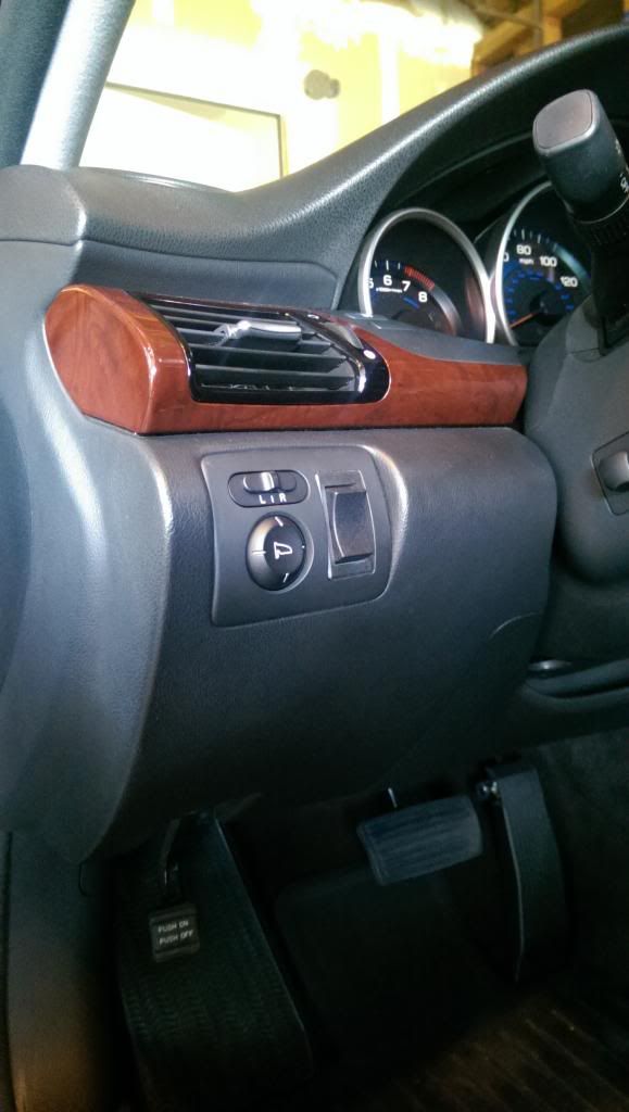
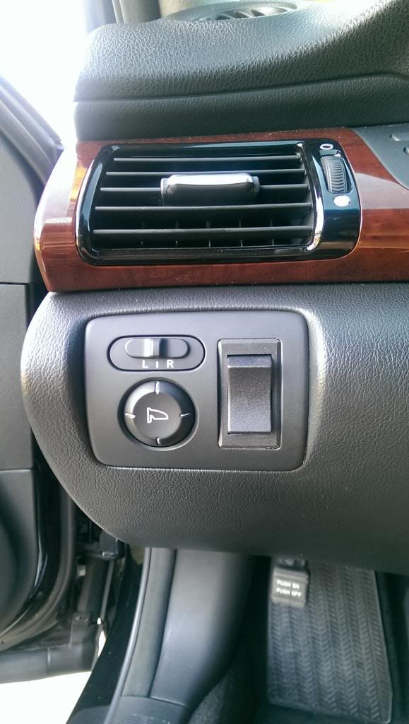
Factory switch removal:
Insert the trim removal kit in the middle of the plate and pry upwards and pull the switch plate out. There are two clips on the bottom that may dislodge once you pull it out. Disconnect the switch harness.
Remove the plastic piece originally used for the windshield washer switch. The aftermarket switch will be used here. The switch that I used required no modifications at all as it simply fits into the empty slot.
Setting up/routing wire harness:
Install the mirror in reverse order of removal. Tighten x3 mirror screws on and route the mirror harness through the hole.
Cut the ends of the two PFM mirror wires and attached them to the 16-18 AWG wire and secure w/ crimping plugs. The white wire being negative and the green wire being positive. You will need at least 3 � feet of wire.
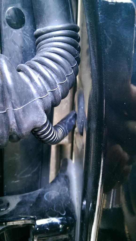
Remove the door harness gasket that attaches to the door and loosen up the harness clip and push in the connector (Do not unplug the connector). This will give you access to run the two wires through the door.
Take the unwind clothes hanger and wrap the two wires around it w/ electrical tape. Remove the white plastic liner enough so that you’ll be able to route the clothes hanger to the door harness. Be sure to route the wires to the side of the door harness connector and not the top or bottom as there’s a clip on the top and bottom to secure the connector in place.
Note: It was impossible to route the wires through the cabin using the location of the door harness. I’ve tried for hours but was unable to do it. I went to plan B and below is process for plan B.
Using a razor blade, carefully cut a 1/4 inch line towards the bottom of the door harness gasket and route the two wires through it. Directly to the side of the door harness should be a rubber grommet. Remove the rubber grommet and cut an X in the middle using a razor blade. Cut a 3 inch piece of wiring loom and insert it in the two wires then route the wires through the rubber grommet.
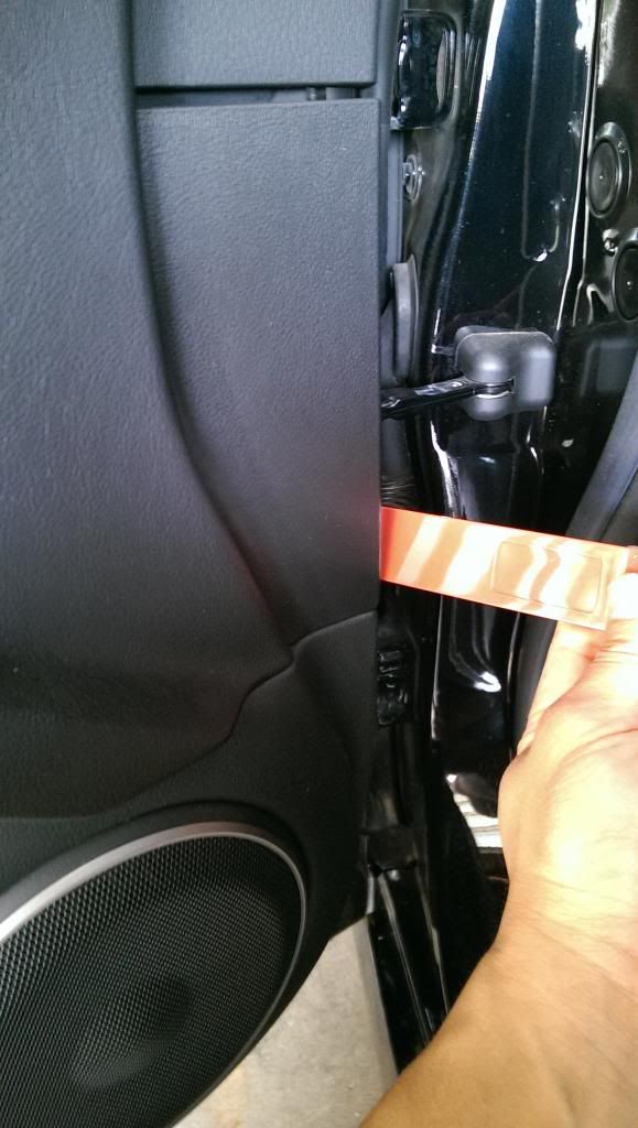
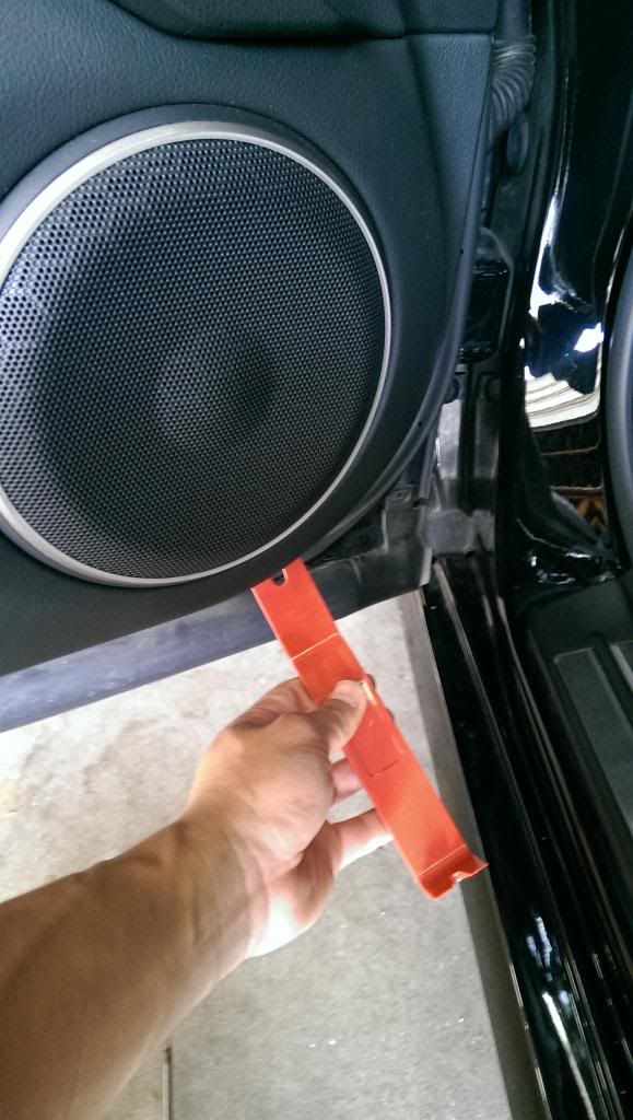
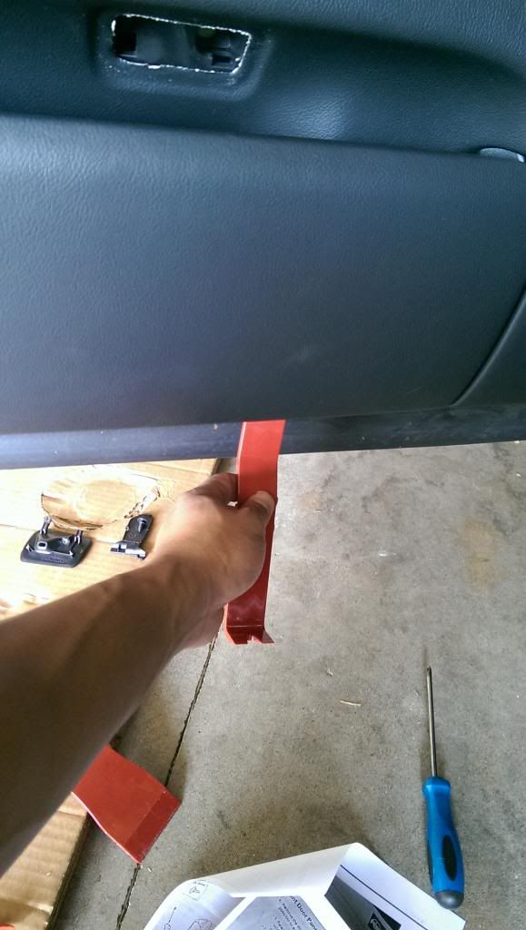
To route the wires through the cabin you will first need to remove the driver’s door sill trim. It is held by four clips. Using a trim remover tool pry the end towards the rear door upwards and work your way left to dislodge the four clips.
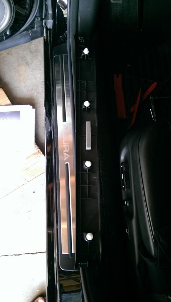
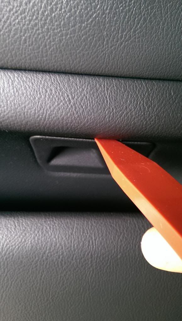
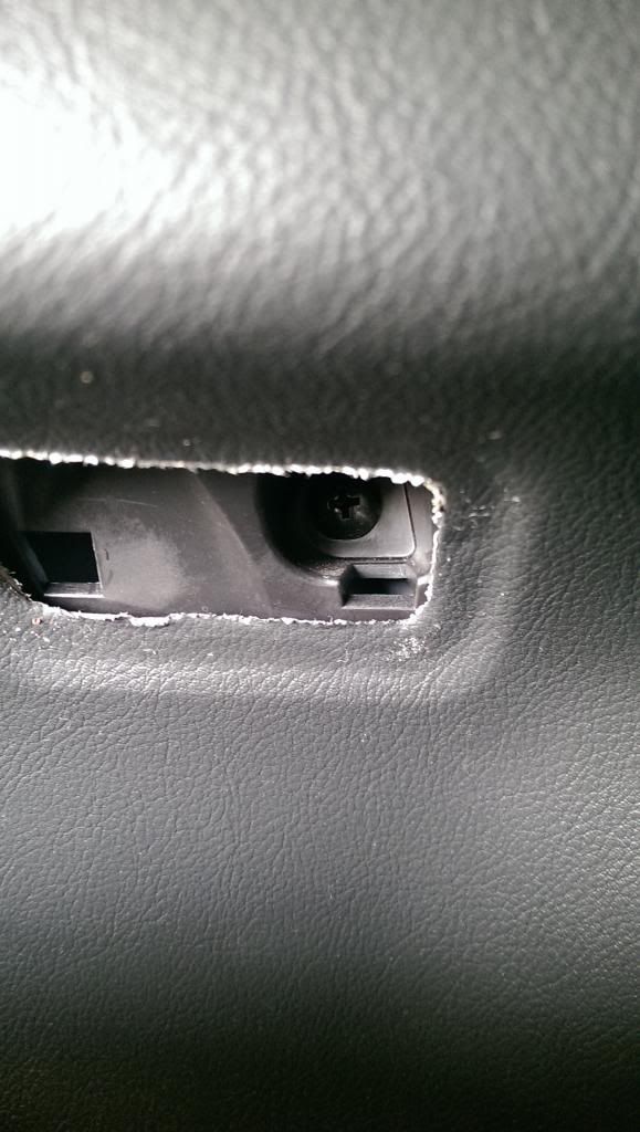
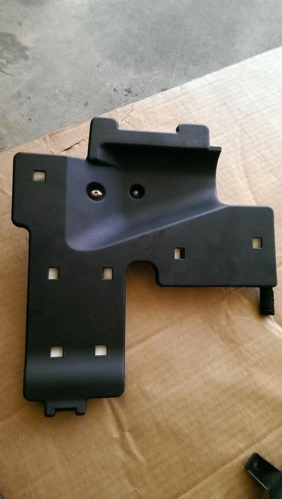
Also the fuse trim will need to be removed as well. It is held by 2 clips (one on the upper right corner and one in the middle). You will first need to remove the upper clip to get leverage and gently pull the trim away to the right.
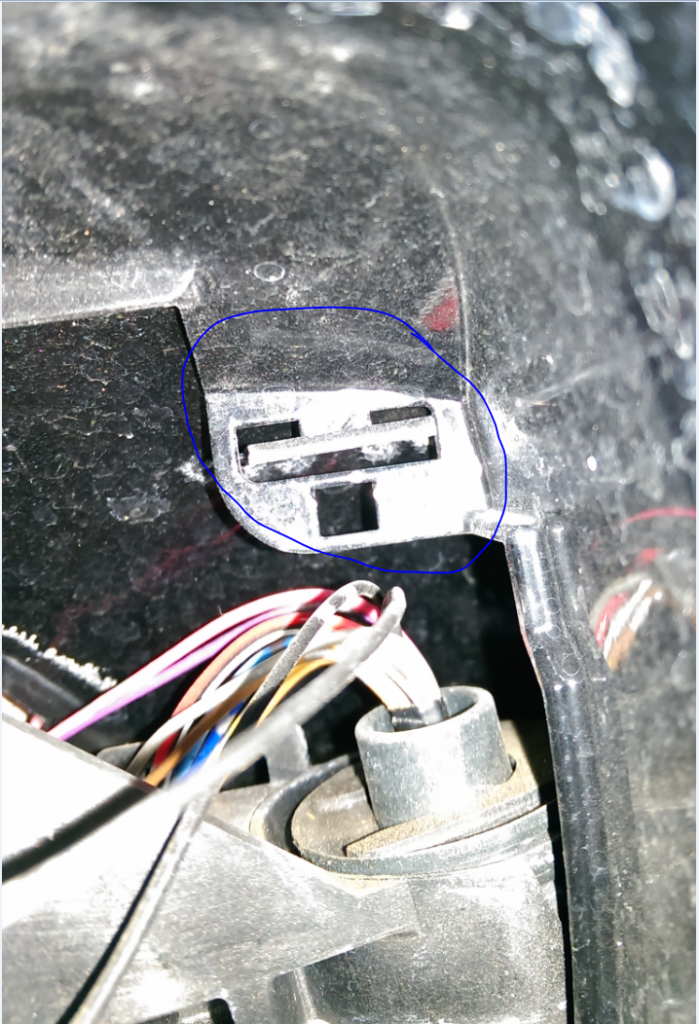
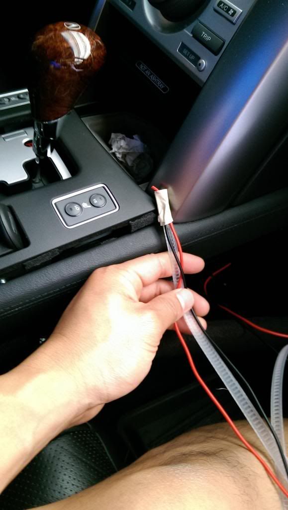
Now you can route the wire through the cabin. Tape the two wires around the wiring routing tool w/ electrical tape and insert it through the grommet hole. There is a small rectangular hole towards the bottom inside the cabin in which you will used to route the wires through. Once the wires are routed through install the rubber grommet and be sure that the wiring loom doesn’t show any access wires. Zip tie the wires to secure them.
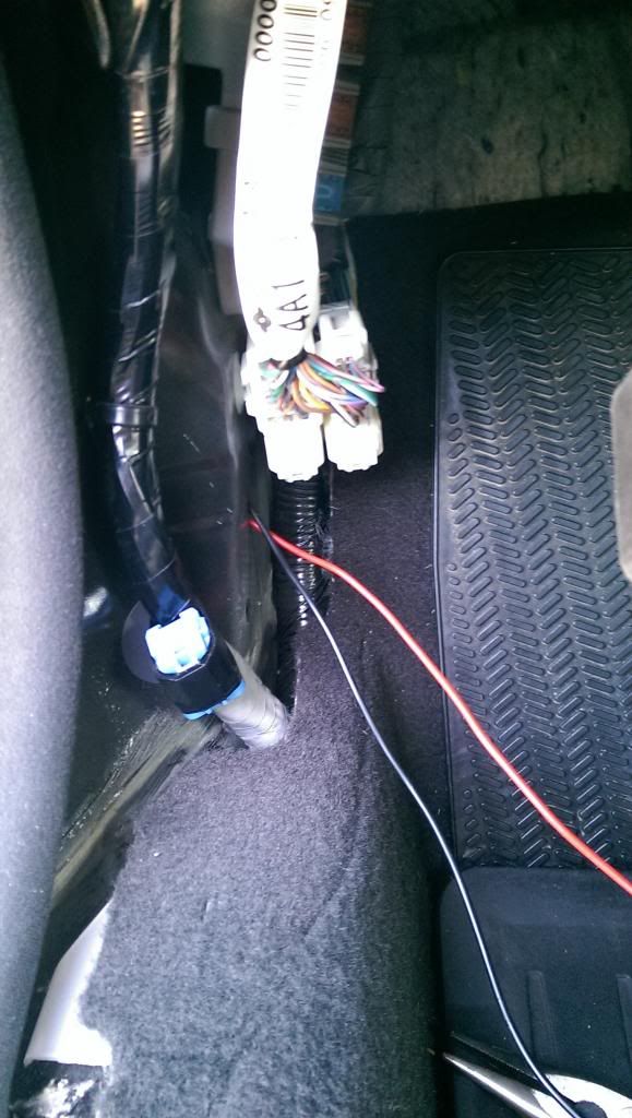
Use the wire routing tool once again and work the tool up towards the switch. Temporarily zip tie it so that it won’t get loose.
Routing wire from passenger side:
Repeat the same process for the passenger side. Routing the wires will be the same up until you have the wires in the cabin. You will need about 5 � feet of wire. The following items will need to be removed in order to route the wires from the passenger side to the switch.
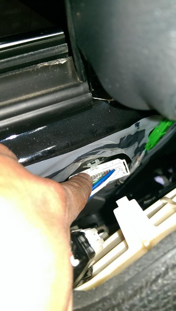
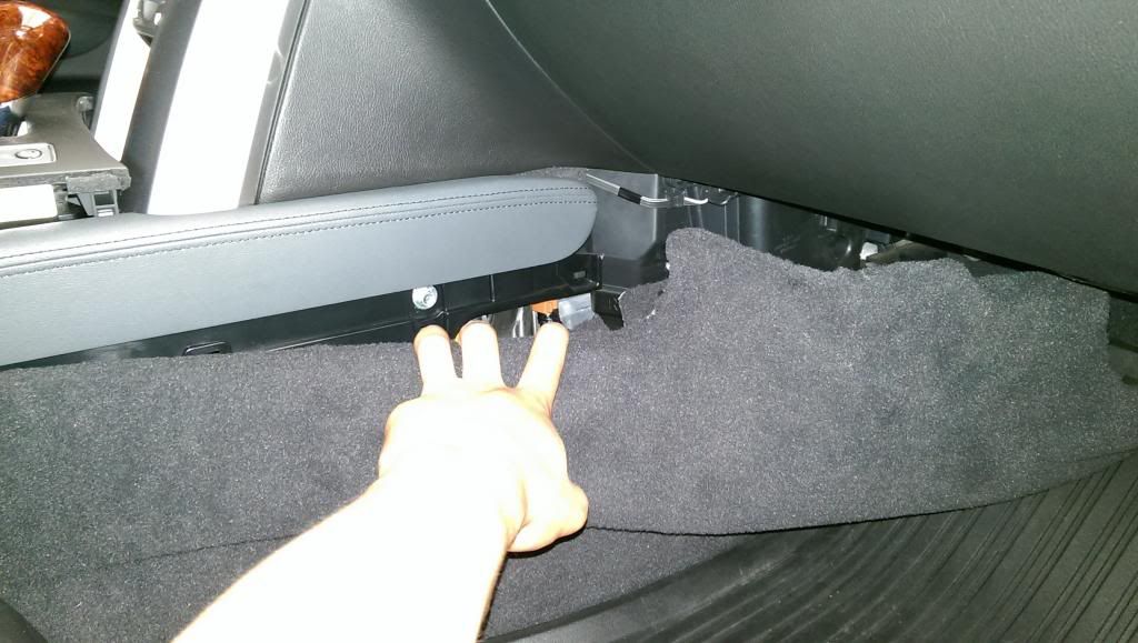
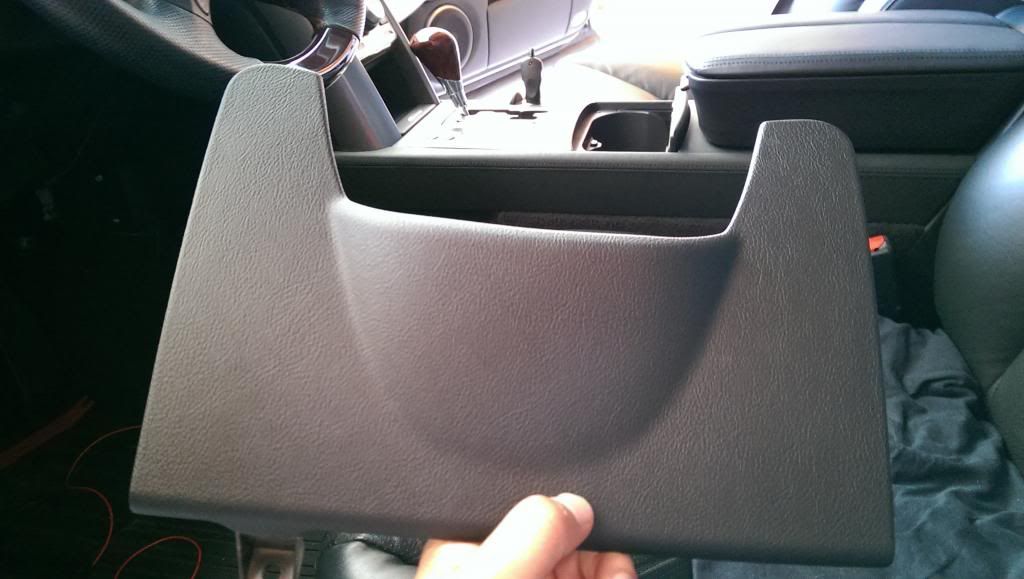
- Remove the glove box under tray trim (show pics)
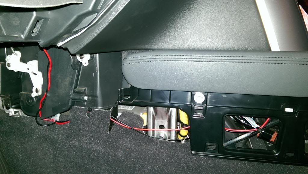
- Remove the driver and passenger carpeted center console sill (show pics)
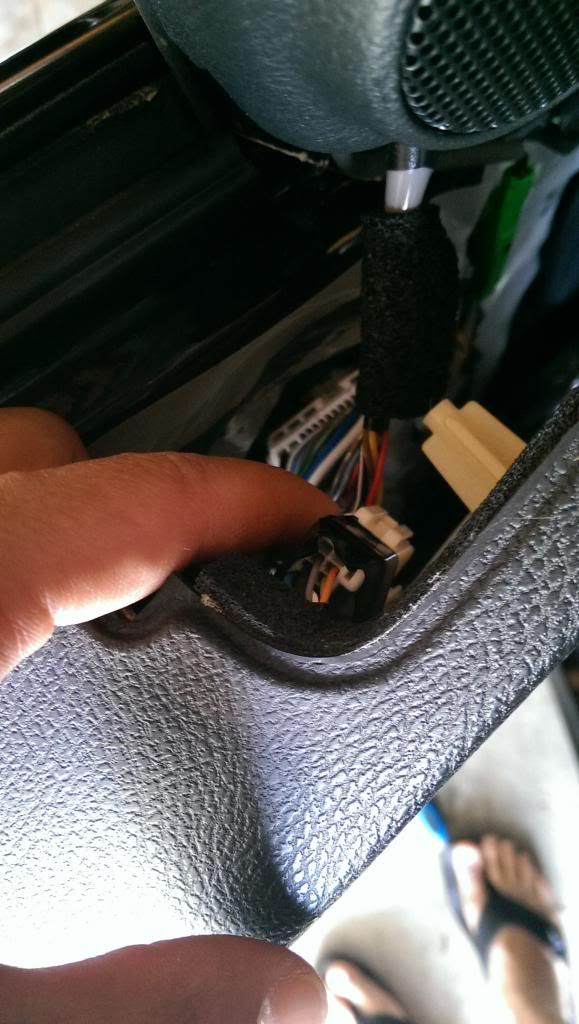
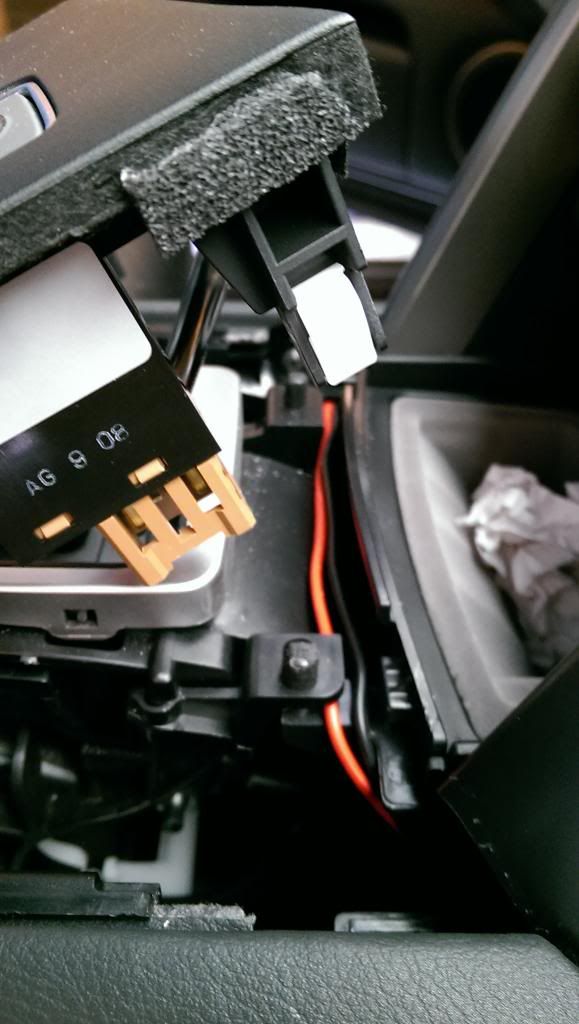
- Remove the center console shift plate (show pics)
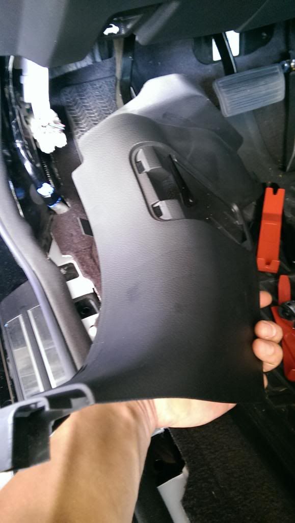
- Remove inner steering column under try trim (show pics)
- Remove outer steering column under tray trim (show pics)
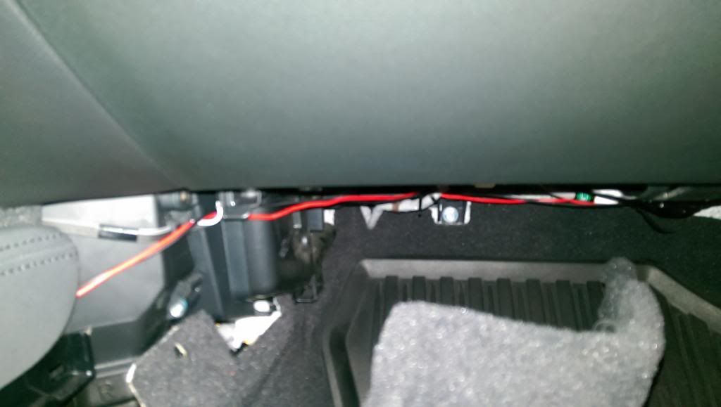
Basically you will route the wires under glove box under tray trim, through the passenger carpeted center console sill, up and around the center console shift plate, through the driver carpeted center console sill, under the inner and outer steering column under tray trim and up towards the switch. Below are some pictures as a reference. Be sure to use zip ties to secure the wires.
[IMG]http://i1066.photobucket.com
/albums/u408/titomang/IMAG0986.jpg[/IMG]
Creating wiring harness:
Here’s a list of what’s needed to create the wiring harness:
� x2 SPDT relays – Autozone
� SPDT On-Off-On toggle/rocker switch
� Add –A-Fuse (ATM)
� In-line fuse (ATM)
� Crimping plugs
� Various size terminal connectors
� Male & female wire connectors
� Electrical tape & painters tape
� x2 16-18 AWG wire (Black & Red)
� Wire stripper
� Wire looms (optional)
(All of the above were purchase at AutoZone)
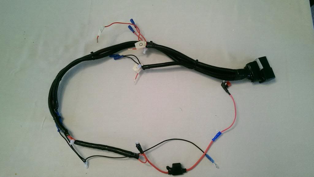
Simply follow this wiring diagram and you should be good to go. Before cleaning up the wiring harness make sure that everything works as it should.
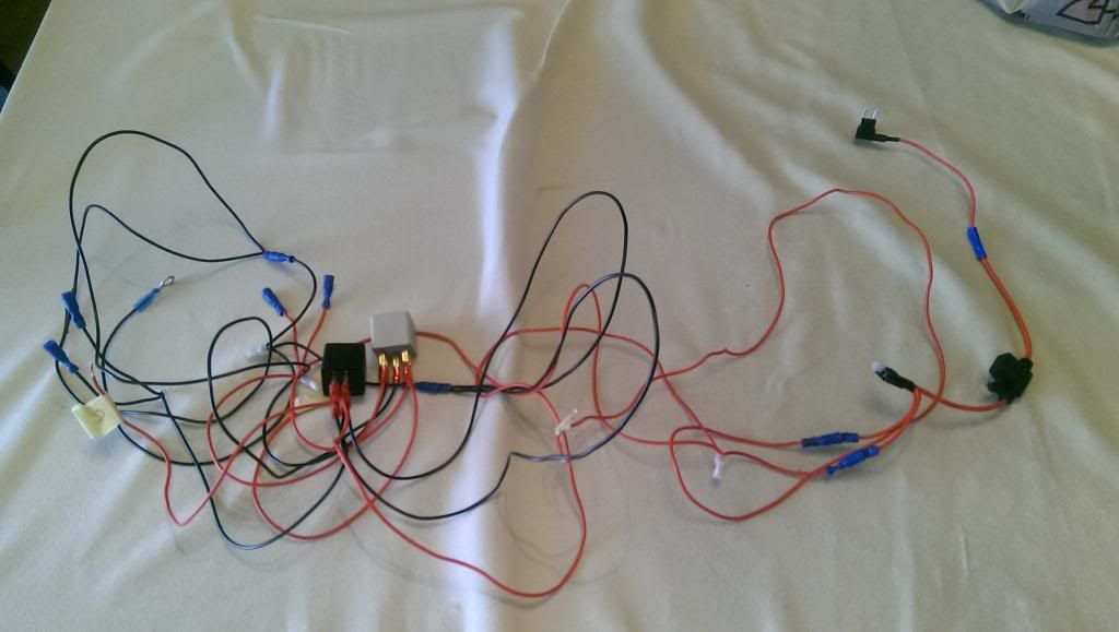
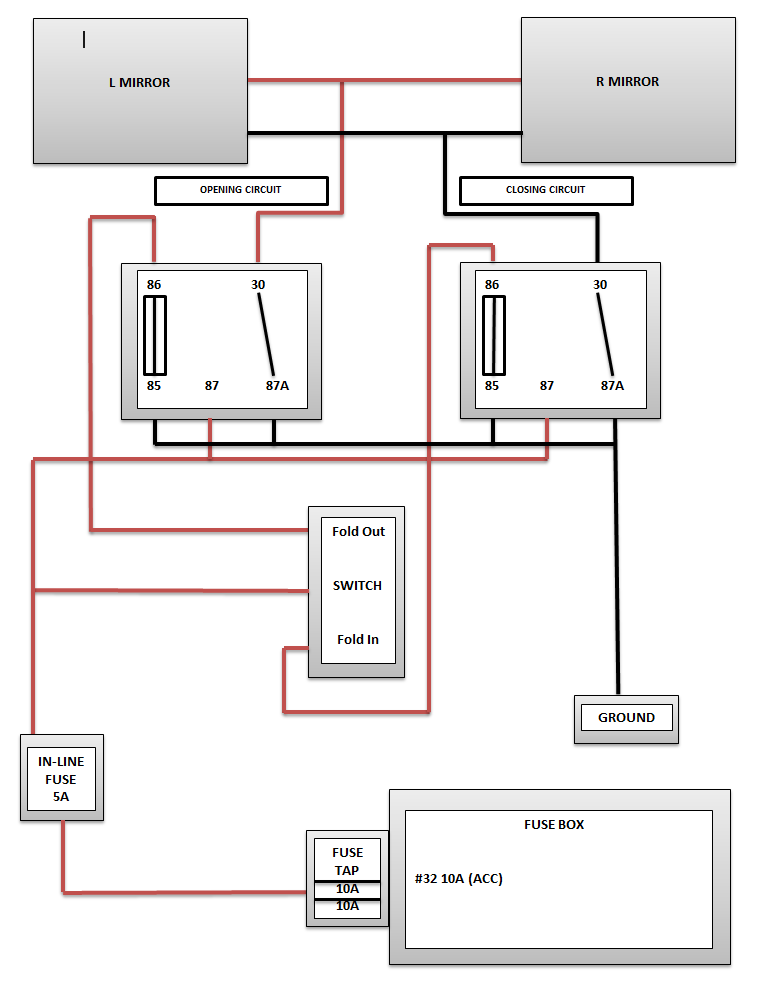
The add-a-fuse will have x2 10 amp fuses and you will need to add x1 5 amp fuse in the in-line fuse holder.
Tuck the wiring harness through the switch location and route the power and ground wire towards the driver’s fuse box. The power wire w/ the add-a-fuse will be inserted in fuse# 32 (ACC) and the ground wire can be grounded to any ground bolt around the fuse area.
Connect the harness mirror wires to both PFM wires and to the switch.
Reconnect the battery and test the function of the PFM mirrors to make sure it works as it should.
Reinstall all trims that were removed and enter in NAV/RADIO code and do the window procedure if necessary.
If everything is well, tap yourself on the back and go have a few beers to celebrate your accomplishment.
http://youtu.be/nSekkWki3bc
http://youtu.be/n1LJylVbdjE
Down the line I will convert my mirrors to fold/unfold when I lock and unlock my car and turn off the function with more relays. This project can seem tedious and overwhelming but to be honest it’s not that bad. Feel free to let me know if you have any questions.
GOOD LUCK!!!
Background:
I was trying to get the set up to be as OEM as possible using the OEM PFM switch but I’ve exhausted all my efforts and couldn’t get the mirrors to fold/unfold using the OEM switch (SEE THREAD: https://acurazine.com/forums/2g-rl-2005-2012-76/where-purchase-oem-parts-overseas-904690/).
I decided to do some more research and ended up drawing my own wiring diagram and creating my wiring harness based off my diagram. I ended up getting it to work with some relays and an aftermarket switch.
You would still need to get the 11-12 RL Advance mirrors ($920) or mirror actuator ($230- the money saving way) to do this conversion. I opted to go with the mirror actuator route since I’m pretty handy.
Before beginning the DIY, be sure to read the entire guide before proceeding. This was written for reference, use the information contained within at your own risk.
Parts/supplies needed:
� R, PFM actuator - #76211-SJA-A11
� L, PFM actuator - #76216-SJA-A11
� x2 SPDT relays
http://www.autozone.com/autozone/parts/_/N-9cikb?itemIdentifier=297371_0_0_
� SPDT On-Off-On toggle/rocker switch
� Add –A-Fuse (ATM)
http://www.autozone.com/autozone/acc...entifier=32416
� In-line fuse (ATM)
http://www.autozone.com/autozone/acc...ier=32420_0_0_
� 10 amp ATM & 5 amp ATM fuse
� Crimping plugs
� Various size terminal connectors
� Male & female wire connectors
� Electrical tape & painters tape
� Electrical wire router (I used a long zip tie)
� Unwind metal clothes hanger
� x2 16-18 AWG wire (Black & Red)
� Wire stripper
� Wire looms (optional)
� Variety phillips/flat head screwdriver
� Torx screw size 20
� Trim removal kit
� 10 MM socket & drive
� Razor blade
In total (minus the research), I spent a total of about 12 hours in a span of a few weeks on this project. I would rate this DIY about a 5/10 in difficulty. The most difficult part is removing the mirrors and routing the wire. A major amount of time was spent on getting the mirrors to fold/unfold with the OEM switch. If I were to do it again, it would take me about 3-4 hours max. Total I spent to do this conversion came out to $300.
PROCESS:
Before disconnecting the battery be certain you have the radio/navi code, both mirrors adjusted in the upward position.
Disconnect the battery:
Remove the negative terminal and put aside in a shop towel
Remove the driver’s door panel:
Remove inner release handle cover. (I applied masking tape over the tip of the flathead to prevent scratches). Push up on clip w/ flathead and use another flathead and pry out from the left side. Remove screw


Remove inner door handle cover w/ a thin flathead. Place thin flathead in slot and pry outwards and remove screw


Remove the door light cover. Use a trim removal tool and insert on top and pry downwards. Remove screw


To remove the door panel from the door shell, start by pulling out the upper right corner of the panel and work your way clockwise. (Use a trim removal kit to help release clips). There are two orange clip on the upper left side and upper middle. After all bottom clips have been removed, tuck your hand in and gently pull out the panel. The door panel is held by clips. Use the trim kit to remove any stuck clips on the door shell and re-attach to the door panel.


Disconnect mirror connector and driver’s main control unit. Take caution of the door handle rod and lock rod. (There is no need to remove rod). Just flip the door panel as shown


In order to remove the mirror you will first need to remove the upper door sill trim. Using a trim remover tool, remove the upper and lower clips and gentle pull outwards until you have access to the 3 mirror screws.
Remove the driver’s mirror:
Using a 10mm socket, remove the x3 screws (hold the mirror while removing screws).


Here's the PDF for reference:


Disassemble mirror:
Mask up mirror w/ masking tape to prevent scratches (Don’t mask up where the outer and inner mirror shell connects)
To remove the mirror, use an angle trim removal tool and insert the tool between the mirror and mirror base and pry left and right to pop out the two bottom latches (one on each side). Unhook the mirror from mirror base and disconnect the two black mirror defogger wires.


The original harness will need to be cut to complete the assembly. Cut the harness at the section where the foam tape ends toward gasket (A new harness will come w/ the actuator)

Use a thin flat head and insert into bottom cover and pry to the left. Use a torx socket and remove x3 torx screws (new screws will be provided).

 Remove mirror gasket then removed the harness tie down clip and remove the mirror base from the mirror while routing the wires through the slots (take note of how mirror harness is routed and the position of wires etc)

The mirror shell will need to be removed in order to remove the mirror actuator housing. You have to be really gentle on the removal process as the clips break really easy. Remove the 5 circled screws as shown (don’t remove the x3 mirror actuator screws until the mirror base is apart).

Remove the turn indicator by popping it out and sliding it towards the right and remove the connector.


After the x5 screws have been removed, begin w/ the upper right clip as shown on picture. Put flathead in clip and push in while carefully pulling mirror shell outwards. Another clip will be on the bottom below mirror actuator housing. Use flathead and push on clip while carefully pulling mirror shell outwards. The last clip will be on the inside towards the right. Use a long flathead and push on clip while carefully pulling mirror shell apart.


Remove the three screws and on the mirror actuator. Disconnect the connectors (black & gray) by pulling upwards starting from the bottom. To remove the harness connector, you will need to remove the white clip then you can disconnect the connector.
Notice that the components are different between the PFM turn actuator and the non PFM turn actuator


Notice the two extra wires absent on the other harness. The brown connector will be inserted into the turn actuator.

Reinstall the mirror components in reversal of disassembly (Be sure everything is connected properly and do not put the wires back into the connector yet until everything is fully assembled)
Mirror removal instructions:


Note: The two black defogger wires can go into any slot on the mirror as they end up being one wire. Also put the foam tape in the same location as it was on the original harness
Using the picture below, insert the pins using the location as shown. Leave the white and green wire as is as the wires will be routed separately.
Factory switch removal:
Insert the trim removal kit in the middle of the plate and pry upwards and pull the switch plate out. There are two clips on the bottom that may dislodge once you pull it out. Disconnect the switch harness.
Remove the plastic piece originally used for the windshield washer switch. The aftermarket switch will be used here. The switch that I used required no modifications at all as it simply fits into the empty slot.
Setting up/routing wire harness:
Install the mirror in reverse order of removal. Tighten x3 mirror screws on and route the mirror harness through the hole.
Cut the ends of the two PFM mirror wires and attached them to the 16-18 AWG wire and secure w/ crimping plugs. The white wire being negative and the green wire being positive. You will need at least 3 � feet of wire.
Remove the door harness gasket that attaches to the door and loosen up the harness clip and push in the connector (Do not unplug the connector). This will give you access to run the two wires through the door.
Take the unwind clothes hanger and wrap the two wires around it w/ electrical tape. Remove the white plastic liner enough so that you’ll be able to route the clothes hanger to the door harness. Be sure to route the wires to the side of the door harness connector and not the top or bottom as there’s a clip on the top and bottom to secure the connector in place.
Note: It was impossible to route the wires through the cabin using the location of the door harness. I’ve tried for hours but was unable to do it. I went to plan B and below is process for plan B.
Using a razor blade, carefully cut a 1/4 inch line towards the bottom of the door harness gasket and route the two wires through it. Directly to the side of the door harness should be a rubber grommet. Remove the rubber grommet and cut an X in the middle using a razor blade. Cut a 3 inch piece of wiring loom and insert it in the two wires then route the wires through the rubber grommet.
To route the wires through the cabin you will first need to remove the driver’s door sill trim. It is held by four clips. Using a trim remover tool pry the end towards the rear door upwards and work your way left to dislodge the four clips.

Also the fuse trim will need to be removed as well. It is held by 2 clips (one on the upper right corner and one in the middle). You will first need to remove the upper clip to get leverage and gently pull the trim away to the right.

Now you can route the wire through the cabin. Tape the two wires around the wiring routing tool w/ electrical tape and insert it through the grommet hole. There is a small rectangular hole towards the bottom inside the cabin in which you will used to route the wires through. Once the wires are routed through install the rubber grommet and be sure that the wiring loom doesn’t show any access wires. Zip tie the wires to secure them.


Use the wire routing tool once again and work the tool up towards the switch. Temporarily zip tie it so that it won’t get loose.
Routing wire from passenger side:
Repeat the same process for the passenger side. Routing the wires will be the same up until you have the wires in the cabin. You will need about 5 � feet of wire. The following items will need to be removed in order to route the wires from the passenger side to the switch.
- Remove the glove box under tray trim (show pics)
- Remove the driver and passenger carpeted center console sill (show pics)
- Remove the center console shift plate (show pics)
- Remove inner steering column under try trim (show pics)
- Remove outer steering column under tray trim (show pics)
Basically you will route the wires under glove box under tray trim, through the passenger carpeted center console sill, up and around the center console shift plate, through the driver carpeted center console sill, under the inner and outer steering column under tray trim and up towards the switch. Below are some pictures as a reference. Be sure to use zip ties to secure the wires.
[IMG]http://i1066.photobucket.com
/albums/u408/titomang/IMAG0986.jpg[/IMG]


Creating wiring harness:
Here’s a list of what’s needed to create the wiring harness:
� x2 SPDT relays – Autozone
� SPDT On-Off-On toggle/rocker switch
� Add –A-Fuse (ATM)
� In-line fuse (ATM)
� Crimping plugs
� Various size terminal connectors
� Male & female wire connectors
� Electrical tape & painters tape
� x2 16-18 AWG wire (Black & Red)
� Wire stripper
� Wire looms (optional)
(All of the above were purchase at AutoZone)
Simply follow this wiring diagram and you should be good to go. Before cleaning up the wiring harness make sure that everything works as it should.


The add-a-fuse will have x2 10 amp fuses and you will need to add x1 5 amp fuse in the in-line fuse holder.
Tuck the wiring harness through the switch location and route the power and ground wire towards the driver’s fuse box. The power wire w/ the add-a-fuse will be inserted in fuse# 32 (ACC) and the ground wire can be grounded to any ground bolt around the fuse area.
Connect the harness mirror wires to both PFM wires and to the switch.
Reconnect the battery and test the function of the PFM mirrors to make sure it works as it should.
Reinstall all trims that were removed and enter in NAV/RADIO code and do the window procedure if necessary.
If everything is well, tap yourself on the back and go have a few beers to celebrate your accomplishment.
http://youtu.be/nSekkWki3bc
http://youtu.be/n1LJylVbdjE
Down the line I will convert my mirrors to fold/unfold when I lock and unlock my car and turn off the function with more relays. This project can seem tedious and overwhelming but to be honest it’s not that bad. Feel free to let me know if you have any questions.
GOOD LUCK!!!
Last edited by titomang; 05-26-2014 at 12:40 PM.

The following 11 users liked this post by titomang:
ChocBoyWonder (05-26-2014),
EL19 (05-27-2014),
fiya (05-31-2014),
Fuchfaccio (05-27-2014),
JDMCRX (04-07-2016),
and 6 others liked this post.

The following users liked this post:
titomang (05-27-2014)
05-26-2014, 12:47 PM
#3
Racer
Thread Starter
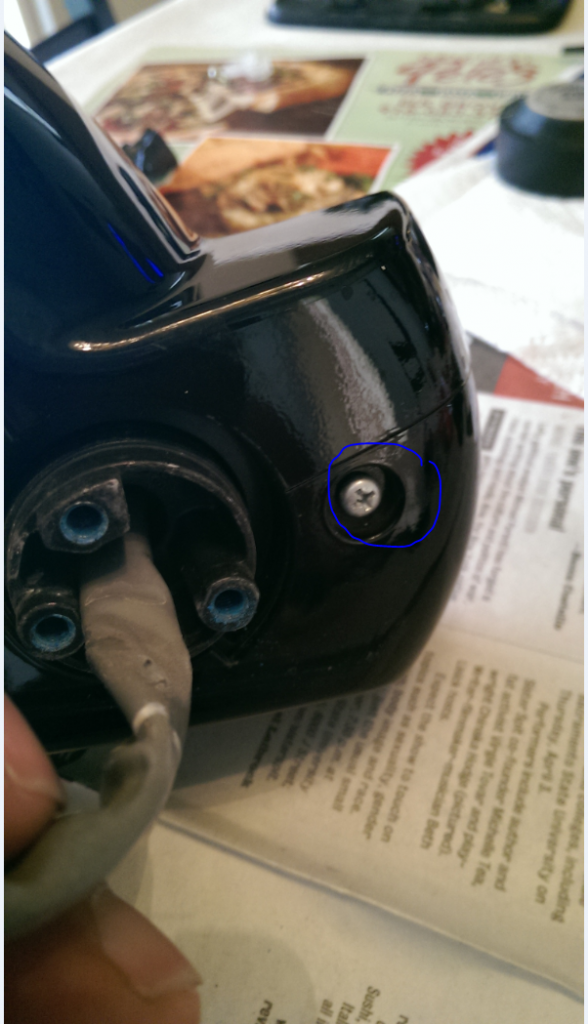
I couldn't edit due to the 15 minute limit. But here's the additional picture of the circled screws that need to be removed along w/ the single one shown above

Also, I have the videos but for some reason it's not showing up. I'll try again in a bit.

Also, I have the videos but for some reason it's not showing up. I'll try again in a bit.
The following 2 users liked this post by titomang:
ChocBoyWonder (05-26-2014),
teh CL (04-05-2016)
05-26-2014, 01:00 PM
#4
Drifting
That's a shit load of work. Nice write-up!
The following users liked this post:
titomang (05-27-2014)
05-26-2014, 01:02 PM
#5
Racer
Thread Starter
Thanks. To be honest, it's not that bad. I tried to provide as much details as possible, hopefully it helps someone get through w/o any trouble.
The following users liked this post:
MarkII (01-02-2022)
05-26-2014, 05:30 PM
#8
Senior Moderator

The following users liked this post:
titomang (05-27-2014)

The following users liked this post:
titomang (05-27-2014)
05-27-2014, 01:39 PM
#10

So if I can ask 2 questions:
1. If someone bought the actual 11-12 Advance mirrors how much time and or work does that save.
2. If those mirrors are bought and installed will that allow us to use the OEM power folding switch which will have to be purchased also I know.
1. If someone bought the actual 11-12 Advance mirrors how much time and or work does that save.
2. If those mirrors are bought and installed will that allow us to use the OEM power folding switch which will have to be purchased also I know.
05-27-2014, 02:29 PM
#11
Racer
Thread Starter
- It�ll save you about 1-1.5 hours tops. Buying the complete mirror will prevent you from having to take the mirrors apart
- Buying the complete mirror and plugging it in will not have the mirrors fold/unfold w/ the oem switch. There�s more to it than just plugging it in. I�ve tried and tried but no luck, the only difference was I went w/ swapping the PFM actuator as oppose to the complete mirrors assembly,
The following users liked this post:
titomang (05-27-2014)
05-27-2014, 04:12 PM
#13
Racer
Thread Starter
This just crossed my mind that I forgot to provide a picture of the switch that I used. I'll upload a picture soon to show what the aftermarket switch looks like.
05-27-2014, 05:38 PM
#14
That was what I meant in my 2nd question was could we use the OEM switch if we bought it. Can it be wired in to work or does it have to be aftermarket like what you used.
05-28-2014, 10:22 AM
#15
Racer
Thread Starter
With enough time and money, I'm sure you can get it to work. I tried to use the OEM switch but couldn't get it to work. I was tired of blowing fuses and just gave up. I think you may need a COM line for it to work then use the HDS to activate it. If someone ever figures it out that'll be great.
06-03-2014, 11:44 PM
#16
Racer
Thread Starter
Here's the picture of the switch that I used. It's made from Marpac part#7-1205. I got it from eBay for $8 shipped. It fits into the slot original used for the windshield washer switch but to make it fit perfectly you need to file it down a bit. A little on top & bottom. Also shape the four corners to mimic the hole.

 06-04-2014, 02:15 AM
#17
No power folding in USA?
Oh my God!..
Why Honda?
Why!..
Oh my God!..
Why Honda?
Why!..
06-04-2014, 08:55 AM
#19
Senior Moderator
The following users liked this post:
T�rk (06-04-2014)
06-04-2014, 10:26 AM
#20
Racer
Thread Starter
Haha. Yup, when it comes to Honda/Acura the rest of the world gets all the goodies then again they're more expensive. I created this write up so USDM owners can have this option if they wanted it.
Hey Choc, yeah, since your in the Canadian market you have the headlight washer switch there. It's going to be difficult to find a switch that'll fit anywhere else unless the button placement you mentioned is the same size as the windshield washer switch. I hope it all works out for you though.
Last edited by titomang; 06-04-2014 at 10:30 AM.
06-04-2014, 11:51 AM
#22
Racer
Thread Starter
06-04-2014, 02:29 PM
#23
 06-04-2014, 02:54 PM
#24
Senior Moderator
99% of the times it doesn't make sense, $$$ is the reason.
12-28-2014, 01:46 PM
#25

Bump.
Met up with titomang on Saturday to tackle this project. Because I was afraid of breaking something he pretty much helped with the mod himself. Much appreciated.
if one has the time and good with electricity then IMO this mod is worth doing. To his point, the most time consuming parts were swapping out the mirror motors and perhaps running the wires.
S/O to titomang for giving up his Saturday morning and helping out an Acurazine fellow!
The following 3 users liked this post by yue3759:
12-28-2014, 09:57 PM
#26
Senior Moderator
Your turn, Choc... 
12-29-2014, 05:59 AM
#27
I might have to resort to an after market switch but my hard head wants to keep trying haha. I landed a pair of jdm mirrors so I will work on swapping the internals. Im seeking out swich and mirror diagrams from the accord to see if its the same switchand how it might be wired differently.
Problem I have with aftermarket switch is where to mount it to look clean since I have headlight washers/switch.
Problem I have with aftermarket switch is where to mount it to look clean since I have headlight washers/switch.
12-29-2014, 06:19 AM
#28
Haha, Titomang got no love from the TL guys haha. Mind boggling..so the TL and Accord are straight PnP with minor modification. The switches look like they work in reverse polarity also.
Titomang, did you try or were you able to get the service manual for those cars to compare diagrams?
Titomang, did you try or were you able to get the service manual for those cars to compare diagrams?
12-29-2014, 10:40 AM
#29
Racer
Thread Starter
Bump.
Met up with titomang on Saturday to tackle this project. Because I was afraid of breaking something he pretty much helped with the mod himself. Much appreciated.
if one has the time and good with electricity then IMO this mod is worth doing. To his point, the most time consuming parts were swapping out the mirror motors and perhaps running the wires.
S/O to titomang for giving up his Saturday morning and helping out an Acurazine fellow!
Met up with titomang on Saturday to tackle this project. Because I was afraid of breaking something he pretty much helped with the mod himself. Much appreciated.
if one has the time and good with electricity then IMO this mod is worth doing. To his point, the most time consuming parts were swapping out the mirror motors and perhaps running the wires.
S/O to titomang for giving up his Saturday morning and helping out an Acurazine fellow!
No problem Stan, I'm willing to help out a fellow AZ member anyway I can. Glad you like it and hopefully it'll be the last mod you do....

BTW, I got the parts from a vendor on here. His SN is OEMAcuraPartsTim, PM him and he should give you a great price.
Haha, Titomang got no love from the TL guys haha. Mind boggling..so the TL and Accord are straight PnP with minor modification. The switches look like they work in reverse polarity also.
Titomang, did you try or were you able to get the service manual for those cars to compare diagrams?
Titomang, did you try or were you able to get the service manual for those cars to compare diagrams?
No I didn't get the diagrams for the TL. I believe the service manual is floating around somewhere.
04-05-2016, 04:38 PM
#30
3rd Gear

Join Date: Feb 2014
Posts: 3
Likes: 0
Received 0 Likes
on
0 Posts
Awesome thread! Sorry for bringing an old thread back to life, but i am looking to modify my mirrors to power folding ones...except i am not very handy and although the process looks pretty straight forward, im afraid i cannot tackle this on my own.
By any chance does anyone know of any shop or private...modifier? that can have this done to my 2014 RDX and wont cost me an arm and a leg? I am in the Vancouver BC area.
Thanks!
By any chance does anyone know of any shop or private...modifier? that can have this done to my 2014 RDX and wont cost me an arm and a leg? I am in the Vancouver BC area.
Thanks!


 04-10-2018, 11:21 AM
#34
Suzuka Master
04-11-2018, 10:12 AM
#36
Racer
Thread Starter
Been MIA for awhile here on the forums. Been busy with a new baby, new house, and new job...haha.
I can send them your way. Let me know what I need to do. Just trying to do my part to help the RL community. BTW, I still have my RL...57k and still going strong.
-Titomang
The following users liked this post:
teh CL (05-24-2018)
05-21-2018, 10:25 AM
#38
Suzuka Master
yup, picture are now back online, great works mod.
03-20-2021, 08:25 AM
#39

- It�ll save you about 1-1.5 hours tops. Buying the complete mirror will prevent you from having to take the mirrors apart
- Buying the complete mirror and plugging it in will not have the mirrors fold/unfold w/ the oem switch. There�s more to it than just plugging it in. I�ve tried and tried but no luck, the only difference was I went w/ swapping the PFM actuator as oppose to the complete mirrors assembly,


Thread
Thread Starter
Forum
Replies
Last Post
fliplyricist1
1G CL (1997-1999)
11
05-16-2008 08:33 AM