Cold Air Intake install help - coolant hose
#1
Instructor
Thread Starter
Cold Air Intake install help - coolant hose
I'm installing a Cold Air intake and the directions aren't very clear about the hose locations, specifically the coolant hose.
I connect one hose from the intake breather to the back of the crankcase. Do I connect The other hose like so?
From #1 to #3 correct?
I connect one hose from the intake breather to the back of the crankcase. Do I connect The other hose like so?

From #1 to #3 correct?
#2
runnin a little boost
iTrader: (3)
The TL runs coolant thru the throttle body to keep the butterfly from freezing in very cold conditions. The hot coolant heats up the IAT sensor ( intake air temp ) causing the car to pull timing and power. You need to bypass the Throttle body and route the coolant from where it enters the TB straight over to where the coolant enters the cooling system. The longer of the two stock hoses will make this connection and the other hose is removed. You can cap the coolant entry and exit from the TB, but it's not needed. Fee free to private message me if you have any further questions. It's super easy once you see how it works.
#4
runnin a little boost
iTrader: (3)
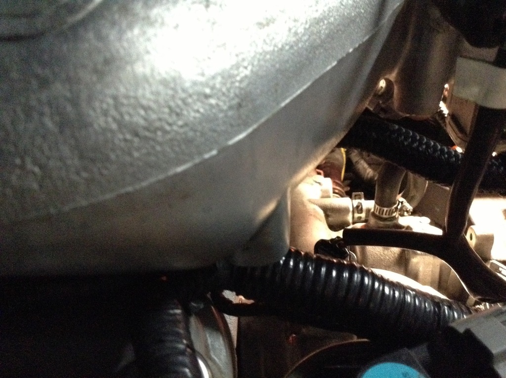
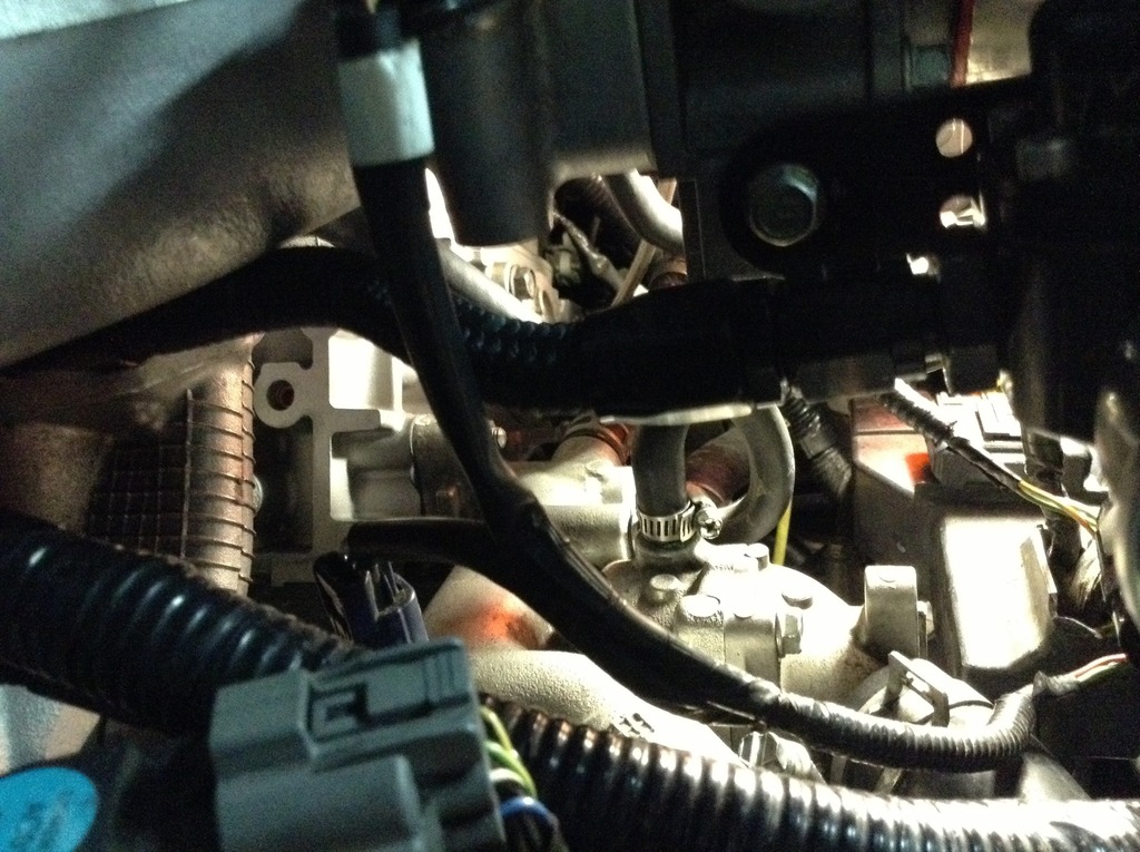
Here you go.


As you can see ( I hope) the connection is very short and the two areas that need to be connected are right next to each other.
For anyone else looking at this thread, this is a great free mod that will make and maintain power levels in a engine known for heat soak.


As you can see ( I hope) the connection is very short and the two areas that need to be connected are right next to each other.
For anyone else looking at this thread, this is a great free mod that will make and maintain power levels in a engine known for heat soak.
Last edited by Hi speed; 05-03-2015 at 02:06 PM.
#6
runnin a little boost
iTrader: (3)
It's easiest to see in the first pic. Locate the worm clamp attached to the black tubing going vertical, that is one end of the bypass. Slightly to the left is a spring clamp (OEM clamp ) that is going horizontal, that is the other end of the bypass. You will see that the two areas that need to be connected are about 1 inch from each other and the tubing is about 3 inches with the loop.
#7
Im planning on installing my CAI and my instructions arent clear for this part as well. I have 2 hoses to install a vacuum hose and heater hose. I have searched youtube and tutorials but nobody specifically shows where the location of each hose is at i know the vacuum hose is from the intake to the back but where is the heater hose and where i reinstall. Can somebody help please
Trending Topics
#8
Pro
iTrader: (1)
Check out the following link from Injen - that should provide clear directions on installing and where to route hoses...etc.
http://injen.com/galleries/products/...2_05012009.pdf
http://injen.com/galleries/products/...2_05012009.pdf


