
getting ready to fix my DRL relay....HELP!
 03-22-2006 | 01:31 PM
#1
Thread Starter
Intermediate
Joined: Sep 2005
Posts: 40
Likes: 1
getting ready to fix my DRL relay....HELP!
I've got a buddy who's handy with a soldering iron, but I wanted to ask one final time for tips on what to look for and how to get there. I've searched the forums and there is no detailed explanation of this fix, other than it's behind the glovebox and it's a relatively easy thing to do.
1) How do I get the glovebox out? Is there anything else I'll need to pull?
2) I've read other people here have re-soldered the bad connection that causes our left DRL to crap out...is it easy to spot?
Any info would be appreciated, I'm driving about an hour away to have someone check it out* and forewarned is forearmed.
*(I'm all thumbs and I don't want to take it to the stealership unless I have to)
03-27-2006 | 02:07 PM
#2
Thread Starter
Intermediate
Joined: Sep 2005
Posts: 40
Likes: 1
DRL Relay FIXED!!
We did it this weekend...it was a remarkably easy job...the hardest part was getting the relay out of the housing, but once out it was pretty obvious which solders were bad, there were 7 or 8 that were either broken or about to go. Now, no more buzzing noise, the DRLs work just fine, and should last for many more years! Thanks to the info on the board. I took some pics, will post a detailed account soon.
03-27-2006 | 02:22 PM
#4
Thread Starter
Intermediate
Joined: Sep 2005
Posts: 40
Likes: 1
Daytime Running Light relay
Daytime Running Light Relay.
Mine was shorting out because some of the solders on the circuit board had become damaged from movement and/or heating & cooling over time. There's a little info on the boards about how to fix it, but it's pretty easy if you know how to use a soldering iron. The damage had caused my drivers side hi-beam to not work, and a buzzing noise was emitting from my dashboard unless I had my lo-beams on. Since my car came over from Canada, I'm not sure if US cars had DRL's standard.
Mine was shorting out because some of the solders on the circuit board had become damaged from movement and/or heating & cooling over time. There's a little info on the boards about how to fix it, but it's pretty easy if you know how to use a soldering iron. The damage had caused my drivers side hi-beam to not work, and a buzzing noise was emitting from my dashboard unless I had my lo-beams on. Since my car came over from Canada, I'm not sure if US cars had DRL's standard.
03-27-2006 | 11:04 PM
#7
Instructor
Joined: May 2004
Posts: 152
Likes: 0
From: Toronto,Ontario
Originally Posted by UnsanePyro
Yeah, I don't think DRLs are a factory piece/option in the US cars, arent' they required by law in Canada though?

Trending Topics
03-29-2007 | 02:33 AM
#9

Intermediate
Joined: Jan 2007
Posts: 33
Likes: 0
Rondo, how about those pics?
Wow, I've had this crappy problem for long time but I just put up with it and turn on my low beams. I was kind of looking forward to seeing pics from Rondo. This thread is pretty old so unlikely to get response.
03-29-2007 | 09:27 AM
#10

Htown slab rider
Joined: Sep 2006
Posts: 404
Likes: 0
From: Houston T.X.
what does it look like now though...i want pix!!!!i want pix!!!!i want pix!!!!i want pix!!!!i want pix!!!!i want pix!!!!i want pix!!!!i want pix!!!!i want pix!!!!i want pix!!!!i want pix!!!!i want pix!!!!i want pix!!!!i want pix!!!!i want pix!!!!i want pix!!!!i want pix!!!!i want pix!!!!i want pix!!!!i want pix!!!!i want pix!!!!i want pix!!!!i want pix!!!!i want pix!!!!i want pix!!!!i want pix!!!!i want pix!!!!i want pix!!!!i want pix!!!!i want pix!!!!i want pix!!!!i want pix!!!!i want pix!!!!i want pix!!!!i want pix!!!!i want pix!!!!i want pix!!!!i want pix!!!!i want pix!!!!
 03-30-2007 | 08:14 PM
#13
Thread Starter
Intermediate
Joined: Sep 2005
Posts: 40
Likes: 1
sorry guys
I forgot all about it, I'll see if my buddy still has the digital shots, but really was as easy as described on the forums...we did the whole thing in about a half-hour....if you know what you're doing with a soldering iron it's pretty clear which solders are bad and need to be touched up. Ill get back to you.
04-27-2007 | 02:38 AM
#14
Thread Starter
Intermediate
Joined: Sep 2005
Posts: 40
Likes: 1
How To Fix Drl Relay (with Pics!!)
Alright, here's Apollo11's writeup of the procedure along with some photos we took when we re-soldered my DRL relay.
Procedures:
1. Remove the glove box.
(There is a piece of string that keeps the glovebox from flopping wide open, you'll have to disengage it for the glovebox to come out. make a note on how to loop it back on the post when you're done. -R)
2. The running light relay is a gray box about the size of a deck of card but twice as thick. It is mounted by a metal tab on the right wall of the glove box cavity.
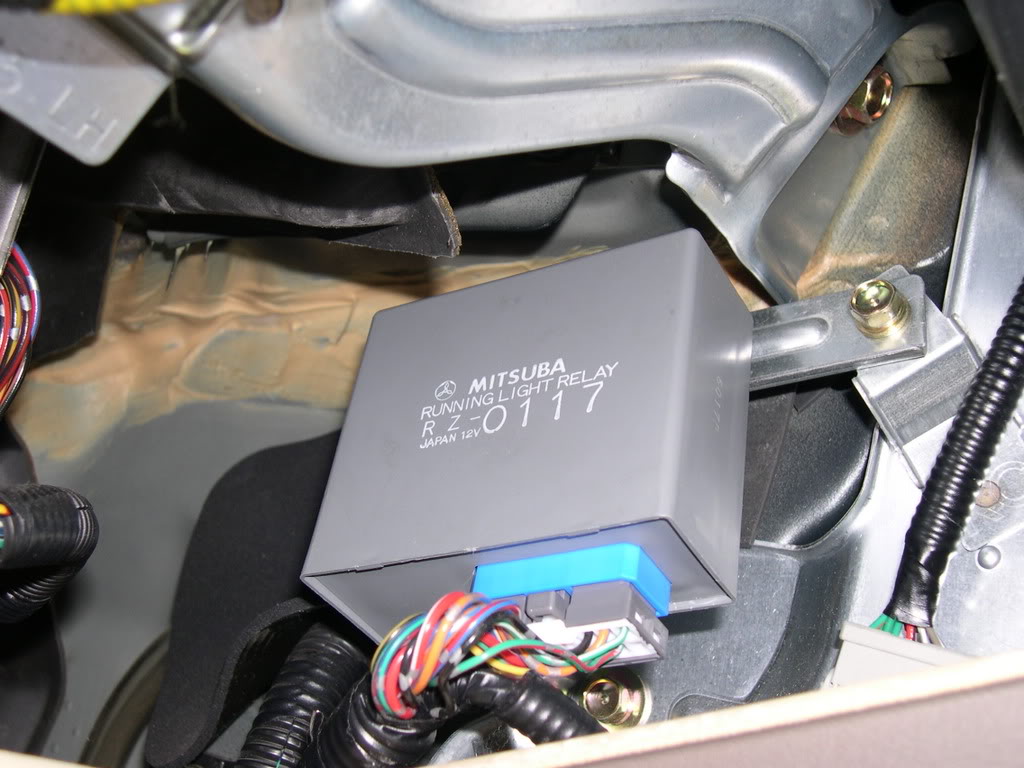
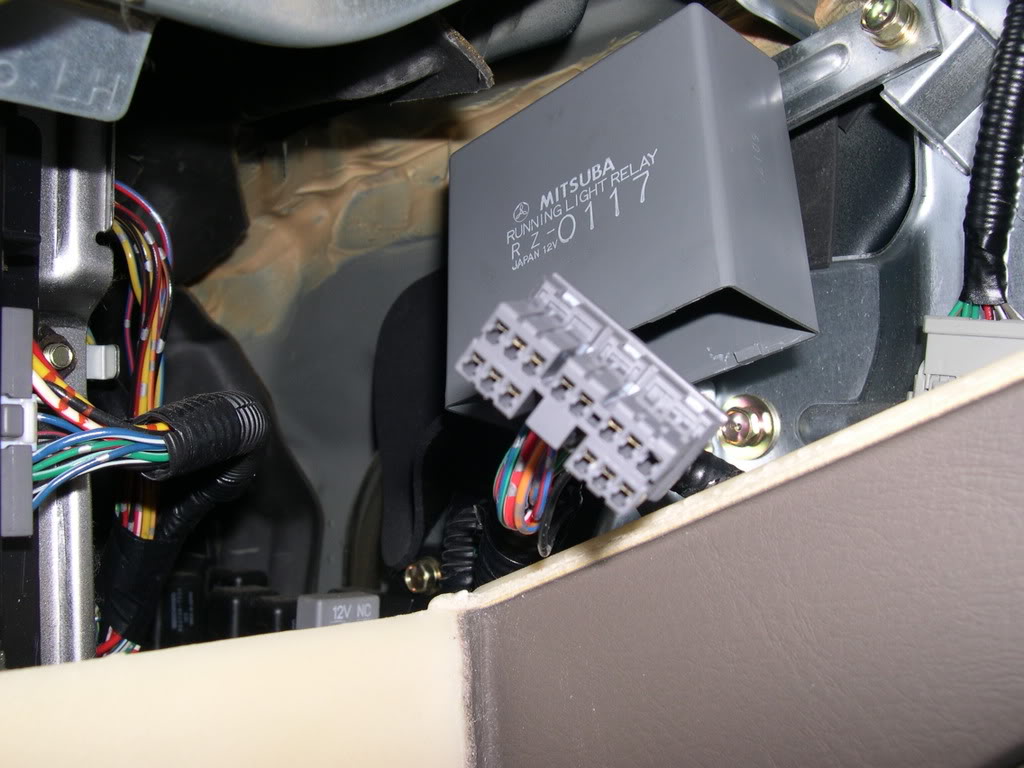
3. Disconnect the wire harness from the relay module. You have to push the locking tab in while pulling the connector down.
4. Use a 10mm wrench to remove the bolt holding the module to the side wall.
5. Take the module and ply the bottom cover off. The circuit board can slide out.
(If memory serves, we just unplugged the module and GENTLY pulled the board out. but don't take my word for it, be careful if it doesn't come right out. -R)
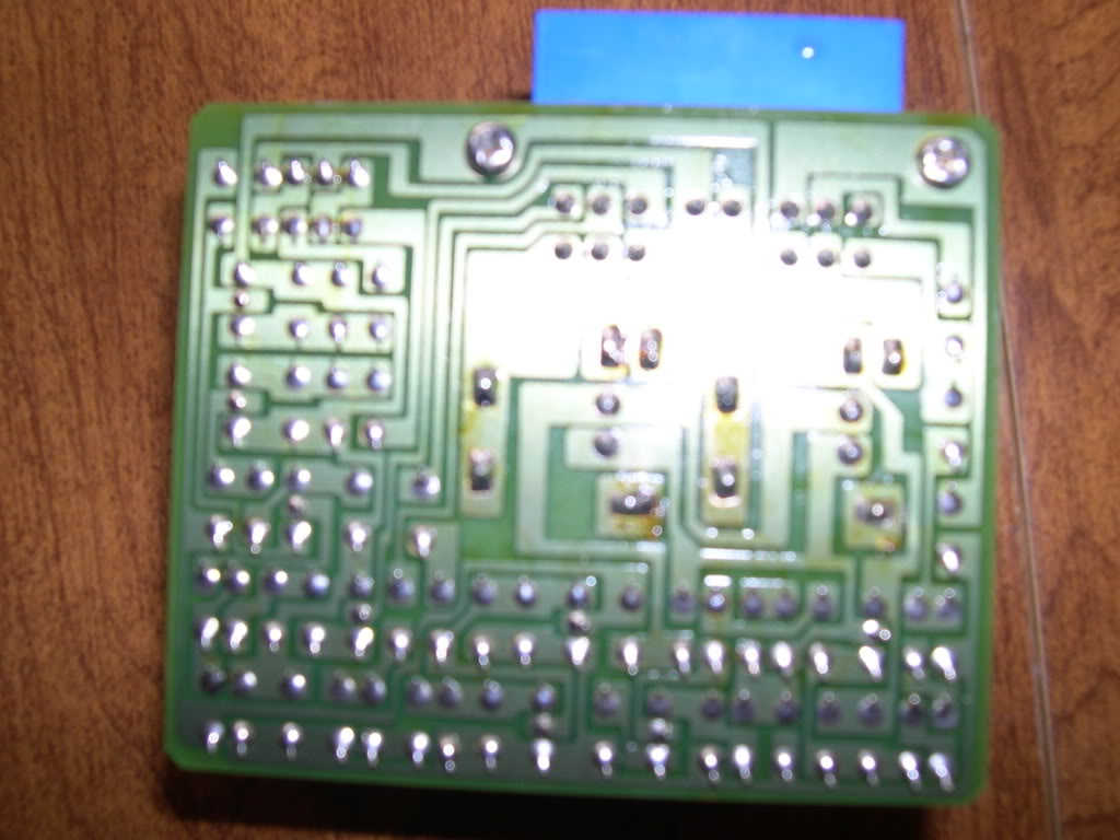
6. There are two big black cubes on the circuit board. These are the relays. Flip the circuit board over to the solder side, and locate the large solder tabs that join the relays to the circuit board. If you look at the solder blobs closely, you may see cracks in them.
Not the best pictures, but you can see the brownish looking solder points..those are the ones you'll need to clean up. when we inspected them, we could see tiny fractures in the solders. Easy to identify and re-solder. -R)

(Since you're in there, make sure to give all the solder points a good look, to see if anything looks like it's coming apart.)
7. Use a soldering iron and remove as much as the old solder as you can. A desoldering tool will be handy.
8. After you clean up the old solder, apply new solder and check that all the solder blobs are nice and shiny.
9. Replace the running light module and it should work.
THANKS TO APOLLO11 FOR THE TIPS, AND MY FRIEND ERIC S. FOR THE SOLDER-FU ON THE CIRCUIT BOARDS! Hope this helps my fellow Canadian TL ownders, that buzzing was annoying!
Procedures:
1. Remove the glove box.
(There is a piece of string that keeps the glovebox from flopping wide open, you'll have to disengage it for the glovebox to come out. make a note on how to loop it back on the post when you're done.
-R)2. The running light relay is a gray box about the size of a deck of card but twice as thick. It is mounted by a metal tab on the right wall of the glove box cavity.
3. Disconnect the wire harness from the relay module. You have to push the locking tab in while pulling the connector down.
4. Use a 10mm wrench to remove the bolt holding the module to the side wall.
5. Take the module and ply the bottom cover off. The circuit board can slide out.
(If memory serves, we just unplugged the module and GENTLY pulled the board out. but don't take my word for it, be careful if it doesn't come right out. -R)
6. There are two big black cubes on the circuit board. These are the relays. Flip the circuit board over to the solder side, and locate the large solder tabs that join the relays to the circuit board. If you look at the solder blobs closely, you may see cracks in them.
Not the best pictures, but you can see the brownish looking solder points..those are the ones you'll need to clean up. when we inspected them, we could see tiny fractures in the solders. Easy to identify and re-solder. -R)
(Since you're in there, make sure to give all the solder points a good look, to see if anything looks like it's coming apart.)
7. Use a soldering iron and remove as much as the old solder as you can. A desoldering tool will be handy.
8. After you clean up the old solder, apply new solder and check that all the solder blobs are nice and shiny.
9. Replace the running light module and it should work.
THANKS TO APOLLO11 FOR THE TIPS, AND MY FRIEND ERIC S. FOR THE SOLDER-FU ON THE CIRCUIT BOARDS! Hope this helps my fellow Canadian TL ownders, that buzzing was annoying!
The following users liked this post:
LoveMDX (02-23-2019)


Thread
Thread Starter
Forum
Replies
Last Post
LogicWavelength
3G TL Photograph Gallery
33
11-01-2015 09:38 AM