Stereo/Gauge Cluster Removal How-To...
 11-16-2013, 11:09 AM
#1
Advanced
Thread Starter
Join Date: Nov 2013
Location: Bailey, Colorado
Age: 64
Posts: 86
Likes: 0
Received 9 Likes
on
9 Posts
Stereo/Gauge Cluster Removal How-To...
Gauge Cluster/Stereo Removal How-To
I picked up a used 2002 RL and it needed the temp gauge bulb replaced. The Nav system is non-functioning and I want to replace it and the stereo with DVD player and video monitor so they are secondary reasons to dig into the dash and figure out how to do both.
To remove the gauge cluster you have to remove the upper console, or at least detach it at the top so the right end of the gauge cluster bezel will come free.
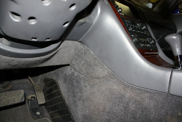
Remove the small, triangular lower carpet pieces by pulling them straight off. They�re held on with clips so be prepared go hunting for the ones that pop off when you pull the panels off. Behind each panel you�ll see a 6mm bolt (10mm head) that holds the bottom of the entertainment/HVAC center in place. No need to remove the bolts at this point. There are two more to be un-covered and removed.

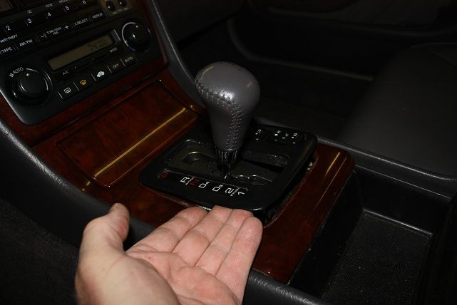
Put the transmission in neutral or D4 (just so it�s centered).
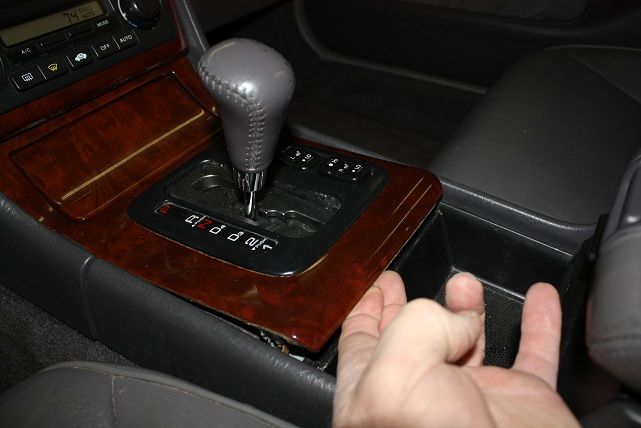
Remove the console panel and gear shift trim in one piece by pulling up on the rear of the console panel to release the clips. The actual shifter gate stays behind with the shifter mechanism.
I picked up a used 2002 RL and it needed the temp gauge bulb replaced. The Nav system is non-functioning and I want to replace it and the stereo with DVD player and video monitor so they are secondary reasons to dig into the dash and figure out how to do both.
To remove the gauge cluster you have to remove the upper console, or at least detach it at the top so the right end of the gauge cluster bezel will come free.
Remove the small, triangular lower carpet pieces by pulling them straight off. They�re held on with clips so be prepared go hunting for the ones that pop off when you pull the panels off. Behind each panel you�ll see a 6mm bolt (10mm head) that holds the bottom of the entertainment/HVAC center in place. No need to remove the bolts at this point. There are two more to be un-covered and removed.
Put the transmission in neutral or D4 (just so it�s centered).
Remove the console panel and gear shift trim in one piece by pulling up on the rear of the console panel to release the clips. The actual shifter gate stays behind with the shifter mechanism.
 11-16-2013, 11:10 AM
#2
Advanced
Thread Starter
Join Date: Nov 2013
Location: Bailey, Colorado
Age: 64
Posts: 86
Likes: 0
Received 9 Likes
on
9 Posts
Part-2
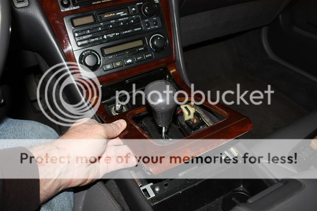
Now reach under the console panel and push the shifter trim up to release the clips holding it in place.
Remove the bulb for the gear select indicator, un-plug the two seat heater switches and then remove the shifter trim piece.
Note: The console panel has a couple hooks to hold it in the front, upper corners.
Pull up on the console panel to release all the clips being mindful of the hooks. Once free, disconnect the lighter socket and remove the console panel. Now is the perfect time to clean up the console pieces and around the shifter itself if needed.
Now look under the upper console for the other two 6mm bolts holding it in place.
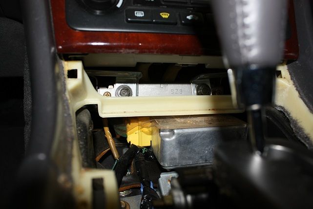
Remove these and the other two under the trim pieces on each side of the console.
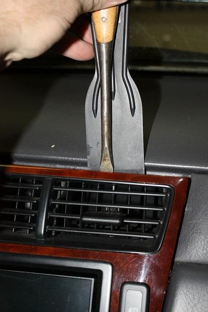
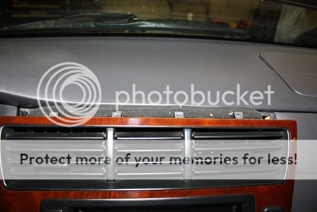
The upper console can now be pulled out on the bottom a bit as it only being held in by the four clips along the top of the center air vent. To release these, I used a 2� plastic putty knife and a very wide std. screwdriver. I started on the right side and worked towards the left. Once one clip comes free, the other release pretty easily. And, yes, you will probably need to go hunting for one or two of them.
Remove the bulb for the gear select indicator, un-plug the two seat heater switches and then remove the shifter trim piece.
Note: The console panel has a couple hooks to hold it in the front, upper corners.
Pull up on the console panel to release all the clips being mindful of the hooks. Once free, disconnect the lighter socket and remove the console panel. Now is the perfect time to clean up the console pieces and around the shifter itself if needed.
Now look under the upper console for the other two 6mm bolts holding it in place.
Remove these and the other two under the trim pieces on each side of the console.
The upper console can now be pulled out on the bottom a bit as it only being held in by the four clips along the top of the center air vent. To release these, I used a 2� plastic putty knife and a very wide std. screwdriver. I started on the right side and worked towards the left. Once one clip comes free, the other release pretty easily. And, yes, you will probably need to go hunting for one or two of them.
11-16-2013, 11:11 AM
#3
Advanced
Thread Starter
Join Date: Nov 2013
Location: Bailey, Colorado
Age: 64
Posts: 86
Likes: 0
Received 9 Likes
on
9 Posts
Part-3
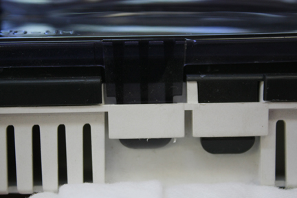
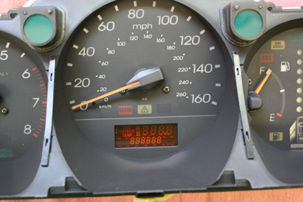
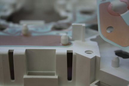
Here�s a pic showing the locations of the four clips. The two in the middle are lined up pretty close the vent dividers. The outside ones are almost in the center of the two adjustable vents.
At this point, if getting the gauge cluster out is your goal, there�s no need to go any further in taking out the upper console. It only needs to be separated enough to get the right end of the cluster bezel free.
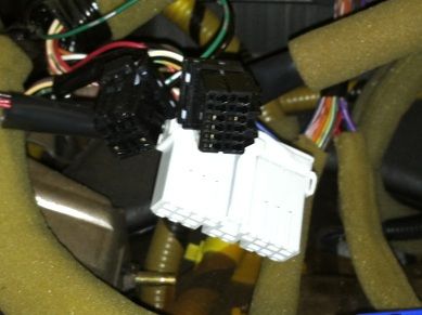
Once the four clips are free and you can pull the upper console out freely, start disconnecting all the switches, stereo/NAV and HVAC controls. I counted 11 or 12! After all the connectors are unplugged, pull the center console straight out.
If getting the stereo/NAV system out is your goal then you�re done. If getting to the gauge cluster is your mission, there�s more to do.
Remove the lower dash panel by pulling on it to release the clips. Again, several went flying on me so be prepared to go hunting for them. Be careful removing the section around the ignition key. It seemed like it would be easy to break off if not patient.
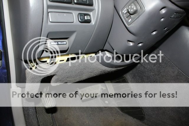
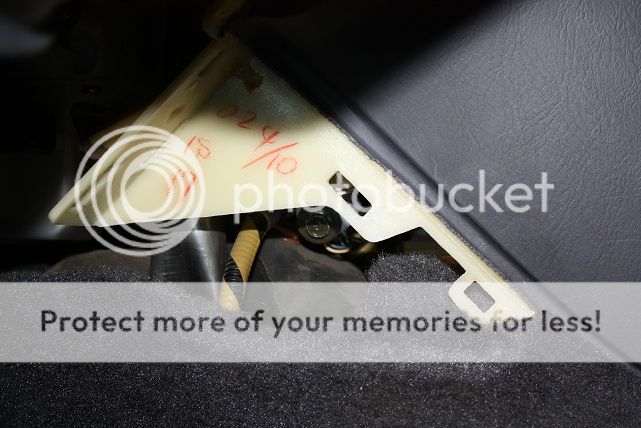
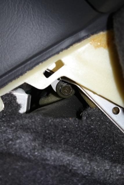
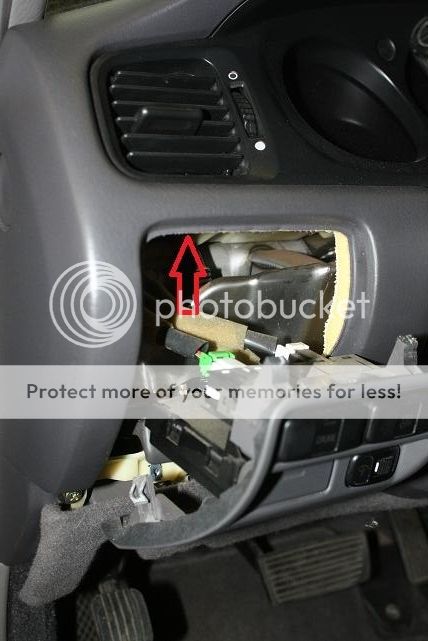
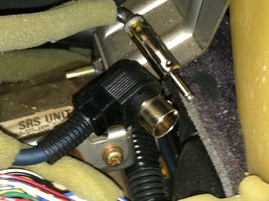
Remove the drivers switch panel by removing the screw below the e-brake release and pulling it out from the bottom. You can unplug the switches and get it out of the way, but I left it hanging without issue. Pulling this switch panel gains you access to the clip holding the lower left corner of the cluster bezel/air vent in place.
At this point, if getting the gauge cluster out is your goal, there�s no need to go any further in taking out the upper console. It only needs to be separated enough to get the right end of the cluster bezel free.
Once the four clips are free and you can pull the upper console out freely, start disconnecting all the switches, stereo/NAV and HVAC controls. I counted 11 or 12! After all the connectors are unplugged, pull the center console straight out.
If getting the stereo/NAV system out is your goal then you�re done. If getting to the gauge cluster is your mission, there�s more to do.
Remove the lower dash panel by pulling on it to release the clips. Again, several went flying on me so be prepared to go hunting for them. Be careful removing the section around the ignition key. It seemed like it would be easy to break off if not patient.
Remove the drivers switch panel by removing the screw below the e-brake release and pulling it out from the bottom. You can unplug the switches and get it out of the way, but I left it hanging without issue. Pulling this switch panel gains you access to the clip holding the lower left corner of the cluster bezel/air vent in place.
11-16-2013, 11:13 AM
#4
Advanced
Thread Starter
Join Date: Nov 2013
Location: Bailey, Colorado
Age: 64
Posts: 86
Likes: 0
Received 9 Likes
on
9 Posts
Part-4
Remove the drivers switch panel by removing the screw below the e-brake release and pulling it out from the bottom. You can unplug the switches and get it out of the way, but I left it hanging without issue. Pulling this switch panel gains you access to the clip holding the lower left corner of the cluster bezel/air vent in place.
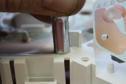
Remove the two screws in the top of the cluster bezel.
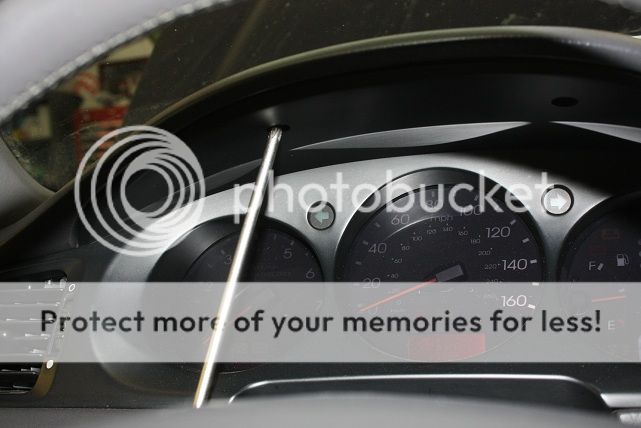
Now comes the tricky part: Removing the bezel.
Lower the steering wheel and extend it out so you have as much room as you can get to work. It takes some finesse but start by getting under the top and pull it out, then work on getting the clips on the right side to come free. Work towards the left and release the clip under the air vent once the bezel seems free (Sorry, I really couldn�t take pics and pull the bezel out at the same time). Once the bezel is free, unplug the trip/temp select/reset switch and remove the bezel completely.
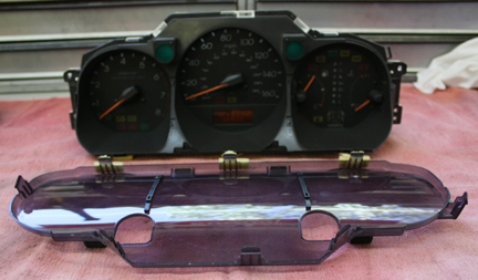
Getting the gauge cluster out is now just a matter of removing four screws, pulling the cluster out enough to get to the plugs to disconnect them and removing the cluster.
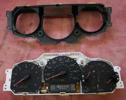
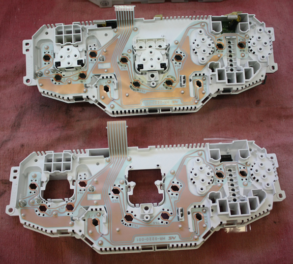
The cluster itself comes apart for access to almost all the bulbs. There are a few that are soldered to the circuit board but the majority are � turn socket types.
Remove the white plastic cover then separate the circuit board from the cluster frame by removing all the screws holding the gauges in-place. Now you can replace what bulbs are out and pull any �nuisance lights� if needed (I have an SRS warning light so I pulled it until my brother can put a scanner on it and figure out what�s the cause). My temp gauge bulb was out so I couldn�t see the needle. All fixed now�
Remove the two screws in the top of the cluster bezel.
Now comes the tricky part: Removing the bezel.
Lower the steering wheel and extend it out so you have as much room as you can get to work. It takes some finesse but start by getting under the top and pull it out, then work on getting the clips on the right side to come free. Work towards the left and release the clip under the air vent once the bezel seems free (Sorry, I really couldn�t take pics and pull the bezel out at the same time). Once the bezel is free, unplug the trip/temp select/reset switch and remove the bezel completely.
Getting the gauge cluster out is now just a matter of removing four screws, pulling the cluster out enough to get to the plugs to disconnect them and removing the cluster.
The cluster itself comes apart for access to almost all the bulbs. There are a few that are soldered to the circuit board but the majority are � turn socket types.
Remove the white plastic cover then separate the circuit board from the cluster frame by removing all the screws holding the gauges in-place. Now you can replace what bulbs are out and pull any �nuisance lights� if needed (I have an SRS warning light so I pulled it until my brother can put a scanner on it and figure out what�s the cause). My temp gauge bulb was out so I couldn�t see the needle. All fixed now�
 12-11-2013, 10:11 PM
#6
Advanced
Thread Starter
Join Date: Nov 2013
Location: Bailey, Colorado
Age: 64
Posts: 86
Likes: 0
Received 9 Likes
on
9 Posts
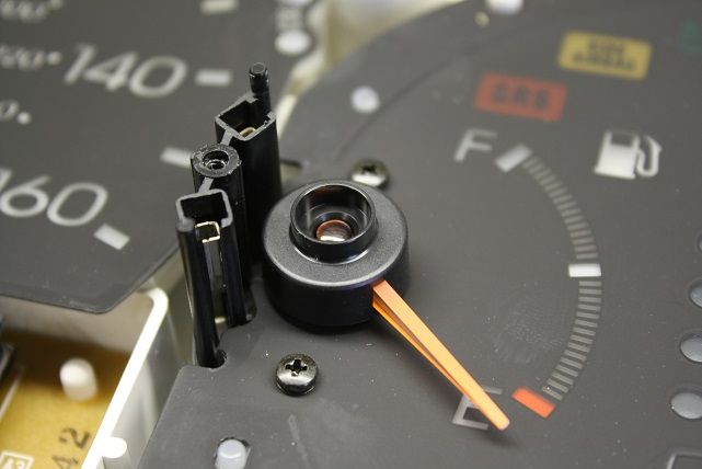
So, after a couple days of driving the car, I lost my temp gauge needle illumination again. The back-lighting was still OK, just no needle. I tore the cluster back out and dug into it further. I discovered that both the temp and gas gauges have 3mm LED's mounted over the movements...
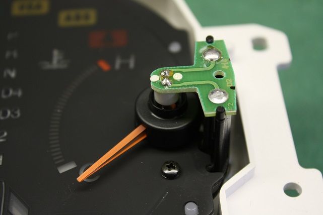
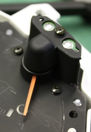
To get to them you'll need to remove the clear plastic cover and the black shroud from the front of the cluster. The gauges are held in by the 5 screws that are also the electrical connections on the back of the cluster.
To get to the LED simply remove the small screw and remove the cover...
The LED is soldered to the "T" shaped PC board. Remove the board by pulling it straight up...
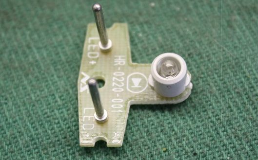
Once it's out, remove the white shade by scraping off the area where it's "welded" to the PCB, then remove the LED using a soldering iron and solder wick (or a "solder sucker")...
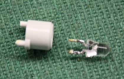
I bought discrete LED's from SuperBrightLEDs.com and replaced both the gas gauge and temp gauge LED's. To hold the shade in-place I just used a dab of silicone adhesive on the base of the LED.
Although my tach & speed-o illumination is working fine, I did try to get the covers off of their movements to change those LED's while I had it apart. They didn't want to pop off with ease and I didn't want to break anything so I left them as-is.
Be sure to get warm white LED's if you can. I used bright white LED's so the needles for the gas/temp gauges look more orange as apposed to the other gauges more reddish color. If/when I pull the cluster again, I'll see if I can get to the LED's for the other gauges.
To get to them you'll need to remove the clear plastic cover and the black shroud from the front of the cluster. The gauges are held in by the 5 screws that are also the electrical connections on the back of the cluster.
To get to the LED simply remove the small screw and remove the cover...
The LED is soldered to the "T" shaped PC board. Remove the board by pulling it straight up...
Once it's out, remove the white shade by scraping off the area where it's "welded" to the PCB, then remove the LED using a soldering iron and solder wick (or a "solder sucker")...
I bought discrete LED's from SuperBrightLEDs.com and replaced both the gas gauge and temp gauge LED's. To hold the shade in-place I just used a dab of silicone adhesive on the base of the LED.
Although my tach & speed-o illumination is working fine, I did try to get the covers off of their movements to change those LED's while I had it apart. They didn't want to pop off with ease and I didn't want to break anything so I left them as-is.
Be sure to get warm white LED's if you can. I used bright white LED's so the needles for the gas/temp gauges look more orange as apposed to the other gauges more reddish color. If/when I pull the cluster again, I'll see if I can get to the LED's for the other gauges.
12-11-2013, 10:38 PM
#7
Advanced
Thread Starter
Join Date: Nov 2013
Location: Bailey, Colorado
Age: 64
Posts: 86
Likes: 0
Received 9 Likes
on
9 Posts
Another issue that came up was the fact that the cluster case is getting cooked by the incandescent bulbs and is so crunchy that pieces were breaking off when I was changing bulbs. I repaired several of the sockets by using some 1/16" thick plastic to make patches. I cut the blanks to fit first then drilled the proper sized hole for the bulb holder. Once the holes were drilled, I used a small file to shape the notches going by the printed circuit for proper orientation. I used epoxy to glue them in place.
It seemed to have worked so far. I haven't had any bulbs go out since doing the repairs.
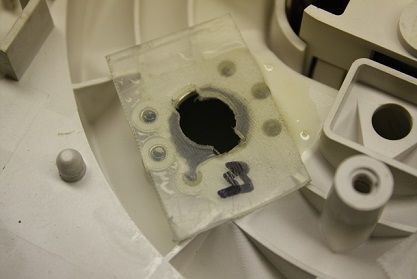
The cluster case is still available from Honda and is about $60 through HPD so around $90 from the dealer I'd guess. I figured I'd give this a try before buying a new case.
It seemed to have worked so far. I haven't had any bulbs go out since doing the repairs.
The cluster case is still available from Honda and is about $60 through HPD so around $90 from the dealer I'd guess. I figured I'd give this a try before buying a new case.
Trending Topics
12-12-2013, 08:42 AM
#9
Advanced
Thread Starter
Join Date: Nov 2013
Location: Bailey, Colorado
Age: 64
Posts: 86
Likes: 0
Received 9 Likes
on
9 Posts
http://www.superbrightleds.com/moreinfo/through-hole/white-3mm-led-30-degree-viewing-angle-3000-mcd/304/1236/
Here's a link to all their 3mm LED's...
http://www.superbrightleds.com/cat/through-hole/filter/LED_Package,3mm,18,166:
And, no, I'm not affiliated with S.B.Led's in any way. I've just found them to be my go-to place for LED stuff. I've been using them for several years and they are great. Most times I get my stuff in 2 or 3 days via USPS.
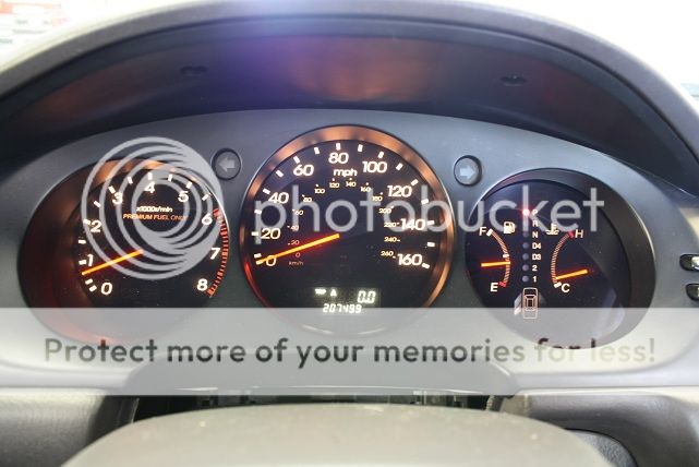
Pic of whole cluster�
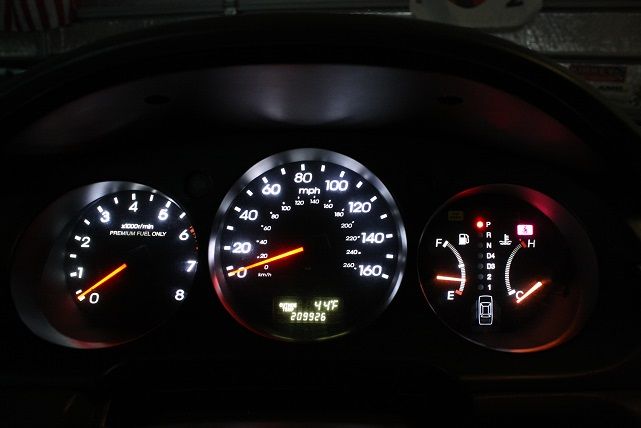
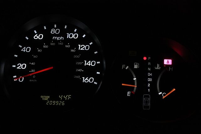
Close-up of temp/gas gauge. You can see the difference in the color of the needles pretty well�
Last edited by El-Baz; 12-12-2013 at 08:51 AM.
 12-12-2013, 11:59 PM
#13
Advanced
Thread Starter
Join Date: Nov 2013
Location: Bailey, Colorado
Age: 64
Posts: 86
Likes: 0
Received 9 Likes
on
9 Posts
http://www.superbrightleds.com/morei...panel-led/219/
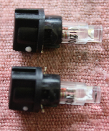
I did discover that the OEM bulb will come out of the OEM socket so you really only need to get the 74 series 12V LED bulbs and not the entire bulb & socket combo. $1.79 vs. $1.19 so you'll save $6 if you buy 10.
These...
http://www.superbrightleds.com/morei...edge-base/226/
These...
http://www.superbrightleds.com/morei...edge-base/227/
Or if you really need some light, these...
http://www.superbrightleds.com/morei...edge-base/228/
12-13-2013, 12:22 AM
#14
Advanced
Thread Starter
Join Date: Nov 2013
Location: Bailey, Colorado
Age: 64
Posts: 86
Likes: 0
Received 9 Likes
on
9 Posts
S.B.LED's does have these but I don't know if they will work...
http://www.superbrightleds.com/morei...panel-led/220/
12-13-2013, 03:55 PM
#16
I'd love to replace the bulbs behind the buttons. If you find out something let us know!!! I've taken the navigation, radio, and ac controls apart before and got a look at the bulbs, and believe me, they are incredibly tiny.
12-13-2013, 03:57 PM
#17
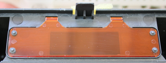
Also, a tip for anyone who is doing the instrument cluster LED replacement. I know the odometer is still that nasty yellow color, and there is something you can do to make it look better. See, the digital display is actually emitting light in a teal color, and it is placed behind a red filter so that the resulting color is the same as the incandescent bulbs. So, when you remove the red filter you get a lot more appealing look for the odometer.
12-13-2013, 07:16 PM
#18
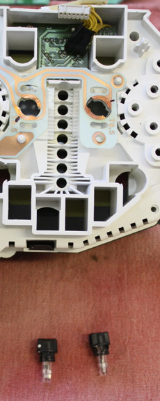
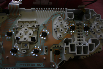
I've got some good news! El-Baz was right on the NEO leds he linked. In total you will need 8 leds for the AC unit. 3x in the 5mm and 5x in the 4mm.
Top left corner 2 are for the Fan speed knob, top middle 3 are for the lcd backlight, and the top right one is for the temp knob. Bottom 2 are for the buttons bellow.

Top left corner 2 are for the Fan speed knob, top middle 3 are for the lcd backlight, and the top right one is for the temp knob. Bottom 2 are for the buttons bellow.
 There are so many of them ! LOL.
12-14-2013, 02:09 AM
There are so many of them ! LOL.
12-14-2013, 02:09 AM
#20
When buying the bulbs, what you will have to consider is this. The natural look of the buttons lit up is green. Yet they use yellow incandescants, that means there is a sort of blue-greenish filter that absorbs the light and makes it green. You may have to try different bulbs to get the desired look.
12-14-2013, 05:09 AM
#21
Some of the bulbs have a white cap over them to change the light a bit. I'm not sure if there is any other filter. When I pulled the bulbs I took a peak behind to check for clearance issues and did not see any filters in there but I could be wrong.
 12-14-2013, 09:37 PM
#24
Advanced
Thread Starter
Join Date: Nov 2013
Location: Bailey, Colorado
Age: 64
Posts: 86
Likes: 0
Received 9 Likes
on
9 Posts
I did some searching for incandescent bulbs to replace the bad switch bulbs and came across these. They have a green filter...
http://www.allelectronics.com/make-a...SE-LAMP/1.html
Only 20 cents a piece. If they lasted 5 years it would be worth it. I'd prefer to use LED's and (hopefully) never have to replace them again. Color choice is a bonus too.
They also have the bare bulbs for 33 cents a piece...
http://www.allelectronics.com/make-a...MM-LAMP/1.html
12-14-2013, 09:48 PM
#25
Advanced
Thread Starter
Join Date: Nov 2013
Location: Bailey, Colorado
Age: 64
Posts: 86
Likes: 0
Received 9 Likes
on
9 Posts
I think the white filters were at one time blue and have faded due to heat/age. I bought some bulbs for my Civic and they came with a sky blue silicone filters. The ones they replaced were faded to almost clear in color.
12-14-2013, 09:59 PM
#26
That could be the case El-Baz I know on some of the other bulbs through out the car they have a light blue cover, but these white covers were solid white when the blues in the car are transparent.
I'd like to find the polarity of the bulbs on the board so its not guess and check for 8 bulbs. Especially since the weather is in the 10s or lower right now =p
I'd like to find the polarity of the bulbs on the board so its not guess and check for 8 bulbs. Especially since the weather is in the 10s or lower right now =p
12-15-2013, 03:04 AM
#27
That could be the case El-Baz I know on some of the other bulbs through out the car they have a light blue cover, but these white covers were solid white when the blues in the car are transparent.
I'd like to find the polarity of the bulbs on the board so its not guess and check for 8 bulbs. Especially since the weather is in the 10s or lower right now =p
I'd like to find the polarity of the bulbs on the board so its not guess and check for 8 bulbs. Especially since the weather is in the 10s or lower right now =p
 12-17-2013, 05:07 AM
#30
Advanced
Thread Starter
Join Date: Nov 2013
Location: Bailey, Colorado
Age: 64
Posts: 86
Likes: 0
Received 9 Likes
on
9 Posts
I think that may the coldest temp I ever seen in my 53 years. It's definitely the coldest I've ever seen in Bailey since I've lived up here. We're back to normal with teens for lows and 40-50 for daytime highs.
12-17-2013, 02:52 PM
#31
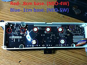
I've got some good info to dump here. So first I was wrong on the AC unit I read the measurements incorrectly from SBL. The bulb list needed for the AC unit is 5x Neo 3x, and 3x Neo 4x.
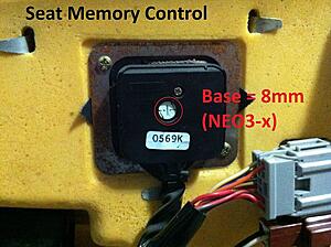
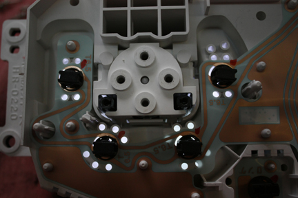
Seat Memory Control on drivers door
Driver Door window switches/ mirror control
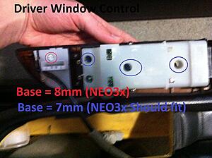
*I'm not sure regarding the 3 blue circles on the drivers door control. The 8mm base will fit fine but the hole is only 5mm when the NEO3x's have a tube width of 5.8mm. You might be able to force the led in but I'm not positive.
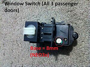
Passenger Door window switches (You'll need 3 of these)
Does the trunk switch have an led in it?
Seat Memory Control on drivers door

Driver Door window switches/ mirror control

*I'm not sure regarding the 3 blue circles on the drivers door control. The 8mm base will fit fine but the hole is only 5mm when the NEO3x's have a tube width of 5.8mm. You might be able to force the led in but I'm not positive.
Passenger Door window switches (You'll need 3 of these)

Does the trunk switch have an led in it?
12-17-2013, 03:23 PM
#33
I sound crazy but I haven't done any yet. I've only been measure the bulbs. It just worked out that I'm vinyl wrapping the wood grain so the parts had to come off. I'll order the leds tonight though including the ones for my cluster backlight.
04-24-2017, 01:50 AM
#35

El-Baz,
I just want to add to the thanks for taking the time to document this process with photos and instructions. Invaluable!
It helped give me the confidence to pursue this on my '98 RL.
In my case, I pursued cluster removal for LED light upgrade, and also re-seated my screws and got my temp gauge working again (bonus!) Everything works and looks awesome now!
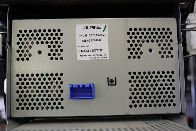
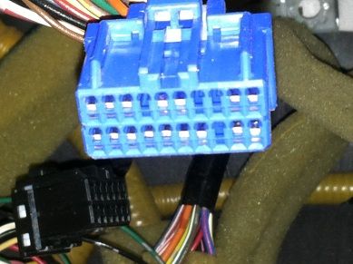
And then I replaced the Bose head unit with a new Pioneer model. The combo (Pioneer 5800 feeding the Boze amp/speakers via a PAC ROEM-HON converter) is awesome!
I also added a rear-view camera, steering wheel controls, and the handbrake bypass. All this took a lot of online prep. Pages such as this helped give me the encouragement to go for it!
Soldered connections, squeezed everything in, closed everything up!
Feels like a new car. (Well, maybe a little hyperbole there.)
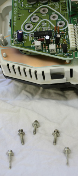
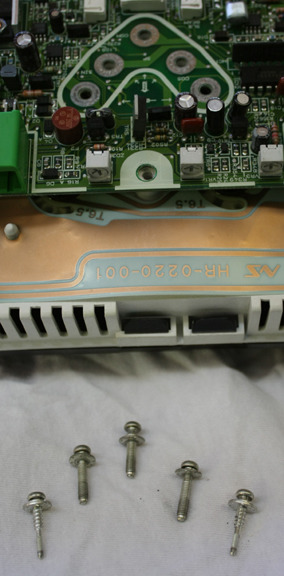
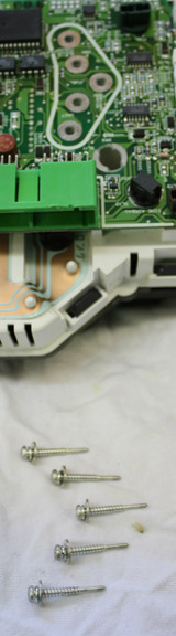
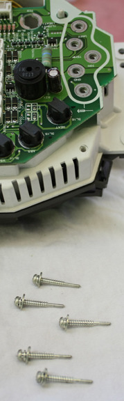
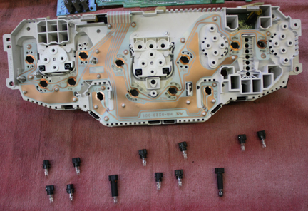
For any benefit of others: The 20 screws on the cluster include 3 types of screws. As some have noted here and elsewhere: You need to keep track of what came from where - and put them back exactly. (I missed this, and lost my fuel guage and have my gear lights. And I broke my cruise light from carelessness. So, be more careful than me!)
The attached photo shows the arrangement of the screws. Notice the diagram on the cluster - for the 2nd set of screws (from left). The first set (far left) is identical). Seat all screws fully, but not forced. Good to go!
I got my LEDs from the Ebay guy from overseas. No issues with him or the bulbs. Worked for me.
Craig
Thanks all.
Craig
I just want to add to the thanks for taking the time to document this process with photos and instructions. Invaluable!
It helped give me the confidence to pursue this on my '98 RL.
In my case, I pursued cluster removal for LED light upgrade, and also re-seated my screws and got my temp gauge working again (bonus!) Everything works and looks awesome now!
And then I replaced the Bose head unit with a new Pioneer model. The combo (Pioneer 5800 feeding the Boze amp/speakers via a PAC ROEM-HON converter) is awesome!
I also added a rear-view camera, steering wheel controls, and the handbrake bypass. All this took a lot of online prep. Pages such as this helped give me the encouragement to go for it!
Soldered connections, squeezed everything in, closed everything up!
Feels like a new car. (Well, maybe a little hyperbole there.)
For any benefit of others: The 20 screws on the cluster include 3 types of screws. As some have noted here and elsewhere: You need to keep track of what came from where - and put them back exactly. (I missed this, and lost my fuel guage and have my gear lights. And I broke my cruise light from carelessness. So, be more careful than me!)
The attached photo shows the arrangement of the screws. Notice the diagram on the cluster - for the 2nd set of screws (from left). The first set (far left) is identical). Seat all screws fully, but not forced. Good to go!
I got my LEDs from the Ebay guy from overseas. No issues with him or the bulbs. Worked for me.
Craig
Thanks all.
Craig
04-24-2017, 12:07 PM
#36
Advanced
Thread Starter
Join Date: Nov 2013
Location: Bailey, Colorado
Age: 64
Posts: 86
Likes: 0
Received 9 Likes
on
9 Posts
You're welcome. I still need to tear mine apart again and replace the entire frame due to the sockets getting "burnt" by the incandescent bulbs. I too had a gauge (tach) stop working after I did mine. Not as critical as the temp/fuel gauges so it's on my list of thing to-do. I'm going to replace the stereo when I do get around to it. I've been using a small tablet and a cassette adapter for a couple years. I just velcro'd it onto the NAV screen (that doesn't work). Beats changing CD's every-other day and if I activate my WiFi on my cell it can be used as a poor man's NAV if needed.
06-14-2017, 08:25 AM
#37
Advanced
Thread Starter
Join Date: Nov 2013
Location: Bailey, Colorado
Age: 64
Posts: 86
Likes: 0
Received 9 Likes
on
9 Posts
Well, it's time for me to get a car that gets better gas mileage so I'm going to buy a 2004 TL this weekend (if all goes to plan) so I need to fix my cluster lights, get the tach working and, if I have time, replace the OEM stereo with a Sony MP3 CD. I'm really glad I created this how-to and posted it because I've since lost the files due to a computer dying. I have the pics but not the text files.
I'll take pics of the cluster re-build. I bought a new frame, printed circuit and the little mounting parts & screws for the gauges. Hopefully all my LED's will light up. I have plenty of spares so it should look good when done. If all goes smooth with the cluster, I'll have time to replace the stereo and I'll document what & how I did it.
My brother is buying the RL from me for his GF, so I'd like to get as much fixed for her as I can. Once I get it done, I'm not going to want to let it go! The '04 TL I'm getting is 6sp w/127k so that will make the "loss" easier to take. Less than 1/2 the miles and much better gas mileage than the RL.
The following users liked this post:
projektvertx (06-16-2017)
06-18-2017, 12:03 PM
#38
Advanced
Thread Starter
Join Date: Nov 2013
Location: Bailey, Colorado
Age: 64
Posts: 86
Likes: 0
Received 9 Likes
on
9 Posts
2002 Cluster Rebuild How-To
Following the removal process...
https://acurazine.com/forums/first-g...al-how-899970/
get the cluster out and onto a clean surface.
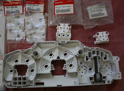
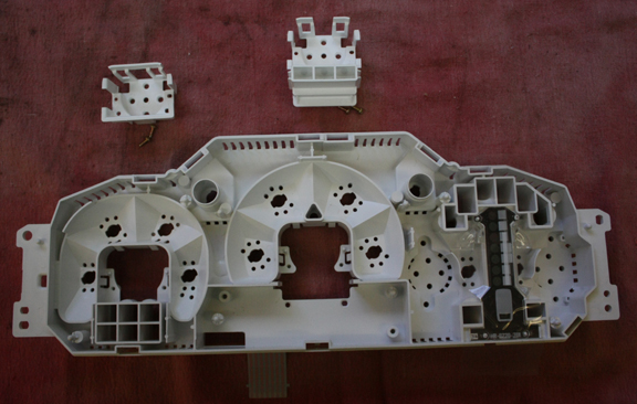
I did a thorough cleaning with Windex and put down a fresh fender cloth and used an old t-shirt to keep things and clean and dust free as possible. Having compressed air is a big plus. I bought a new frame, the PCB, the mounting parts for the speed-o & tach and some extra “wood screws”. The longer course threaded screws.
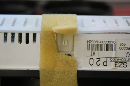
Once you have the cluster out, start by removing the white cover on the back. It’s held on by three gold screws and several snap tabs. Three of the snap tabs are under the yellow foam.
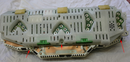
Once all the tabs are free, pull the cover off. Unplug the 2 tan connectors. Use a small blade screwdriver and start at one end and get it loose then rock it back & forth so you don’t bend the pins. If you do, use a needle nose pliers to straighten them. Be careful not to go too far and snap them off.
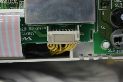
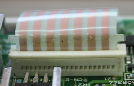
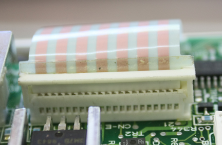
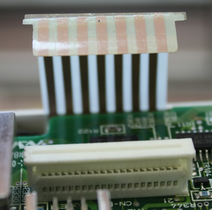
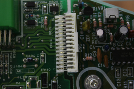
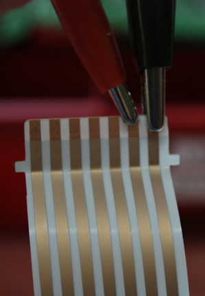
Unplug the ribbon cable by prying up the capture bar at both ends and pull the ribbon out of the connector.
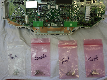
Remove the screws from the gauges. Keep track where each one comes from. There are two different length “wood screws” and machine screws.
The board should come off the frame now. Mine had a couple pieces of double stick tape so it didn’t just come free, I had to work those spots free. Watch out for the connector from the main board to the tach board. It looks like it could easily be damaged and wouldn’t be any fun to fix. It may come apart but I've dealt with those types of connectors in other devices and they are PITA to get back together. I just held both sections and took them off as a unit.
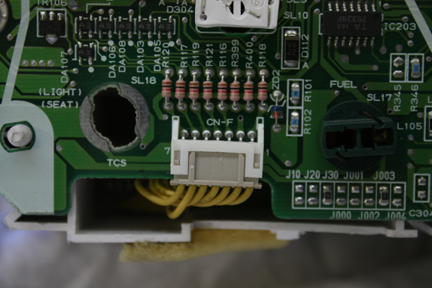
If you previously installed LED’s, mark which side of the socket is positive. I got 1/3 of the way through when I realized I didn’t. Not a huge deal as I figured out a way to check them before reassembly and marked them after the fact for future reference. The 2 long ones are for the turn indicators. Notice the one on the right is black. It needs replaced which became an issue for me later.
This is the fuel/temp gauge section. Notice the little black dot on the board where the left most LED's goes and the white dot on the LED. They mark the positive terminals. The LED’s from Super Bright LED’s came marked so I just had to add the dot to the board. The mark by the right most LED is a piece of "stuff", not a mark. I didn't notice that when I took the pic so disregard it. If you follow the circuit it obvious which terminal is +12V and which is GND. Once I got all of them working I used a red Sharpie to mark them clearly.
At this point I noticed my assistant wasn’t around. She got bored and went back into house for a nap.
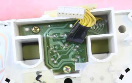
Remove the little circuit board for the door open warning lights.
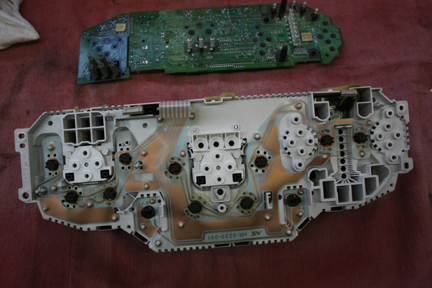
Flip the cluster over and remove the black “glass” by releasing the snap tabs holding it in-place. There are snap tabs for the inner face too, so don’t confuse the two. The one on the left is for the glass, the one on the right is for the inner face.
Some are hidden under the yellow foam. Just peal back the foam and release them.
Once all are released you can remove the glass.
There are two rubber seals between the gauges. Mine were stuck to the glass, so I peeled them off and put them back on the inner frame. I could then clean the glass really good before reassembly.
At this point I would go wash my hands. The flat black inner panel is really bad for showing finger prints. I hate wearing latex gloves but that would work too. Now release all the snap tabs for the inner face. Be careful because it’s the only thing holding the actual gauges in-place.
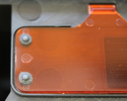
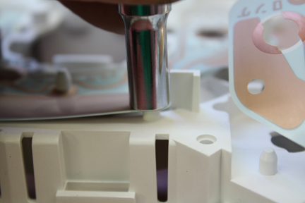
On mine the little chrome cups on the back of the temp and fuel gauges would just fall right off. I just gave them a pinch so they were just bit oval shaped so they would stay on once reassembly began. Remove the gauges and set them aside in a safe, clean spot, and cover them so they don’t get dusty. Now remove the information display. Note: If you wanted to change the color, it would be a matter of replacing the orange lens with something of a different color. It would have to be handmade but doable for sure. Perhaps using clear Lexan with window tinting to modify the color might work.
I bought a new frame, the little gauge mounts, the PCB for the back lights and some extra long, course screws so I was ready to reassemble everything at this point. If you’re only replacing either the frame or the PCB, you’ll need to separate the two. The PCB comes of fairly easy. It’s just a matter of getting ahold of the PCB on each side of the pins and pulling it free. Go slow and don’t stretch or tear the PCB. Once out, it’s easy to clean up the contact areas with a scotch bright pad. Don’t get carried away as the copper film is pretty thin. The little gauge mounts are held in place with small screws as well as clipping into place. PITA but I got them out OK. I just needed the screws but removed them out of curiosity.
To install the new PCB on the new frame I used a �” drive, �” deep socket. It worked perfectly and fit right over the pins so I could press the PCB over each one.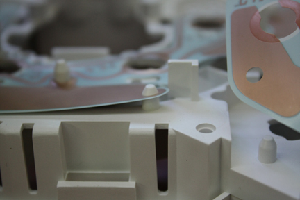
Old vs New…
Assembly is just reverse of disassembly. Take your time, keep everything clean.
Now the PITA part. Once I got everything together and installed the cluster in the car. I checked that everything lit up and the gauges work. I had my car on a lift so I started it and put it in gear and let the front wheels turn enough for the speed-o show me it was working. The tach still wasn’t working so I’m not sure where it’s gone bad. It was fine when I first did the LED swaps a few years ago and assumed it was a bad connection. I fiddled with all the plugs and such but couldn’t get it to work. F-it, I can live without it. So I put everything back together only to find out that the right turn signal indicator wasn’t working. I knew when I saw the bulb all black I should replace it, but I didn’t have one so I took a chance… Bad choice!!! Oh well, I didn’t have time to tear everything back out that day and left it. I took if for a drive to check op’s on everything else and all seemed well until I hit the top of my driveway and got out onto my dirt road. I had several LED’s that started flickering. If I gave the dash a smack they would come on but I couldn’t leave it like that. A couple days later, I tore out the cluster again. Much easier when you’re not removing the center console/entertainment center. It only took 45 minutes and I had it back on the bench.First up was replacing the turn indicator bulbs with LED’s. The OEM bulbs just pull off the long sockets so I used a couple of my blue LED’s. I tried the high output ones first but they were way too bright. The standard output blues worked just fine and with the green lenses they are just a touch towards cyan in color but still green enough no one would notice without a side-by-side comparison. Next was dealing with the flickering back lights. What I finally did was I found an old 12VDC transformer from a modem or some other long gone POS. I cut the plug off and replaced it with gator clips.
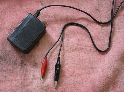
I could then unplug the ribbon cable and clip the gators to it and check LED op’s on the bench. Note the red marks by the LED's for the tach. Those are the ones I didn't mark before disassembly. After I made sure everything was working solid, I marked them for future reference. All the other back lights have the positive terminal on the opposite side so it's good to mark them before removing them.
With the end up and the copper side facing you, from left to right, the pin-outs for this connector are as follows:
Tach lights_+12VDC
Tach lights_GND
Left Turn_+12VDC
Right Turn_+12VDC
Turn Indicator_GND (for both)
Speed-O, Fuel & Temp_+12VDC
Speed-O, Fuel & Temp_GND
I'm clipped to the Speed-O, Fuel & Temp gauge circuit in the pic above.
To fix the flickering, I just bent the contacts on the bulbs out a little so I had a tighter fit and therefore a better connection.
Except for the tach not happy, it’s all working and looks pretty good.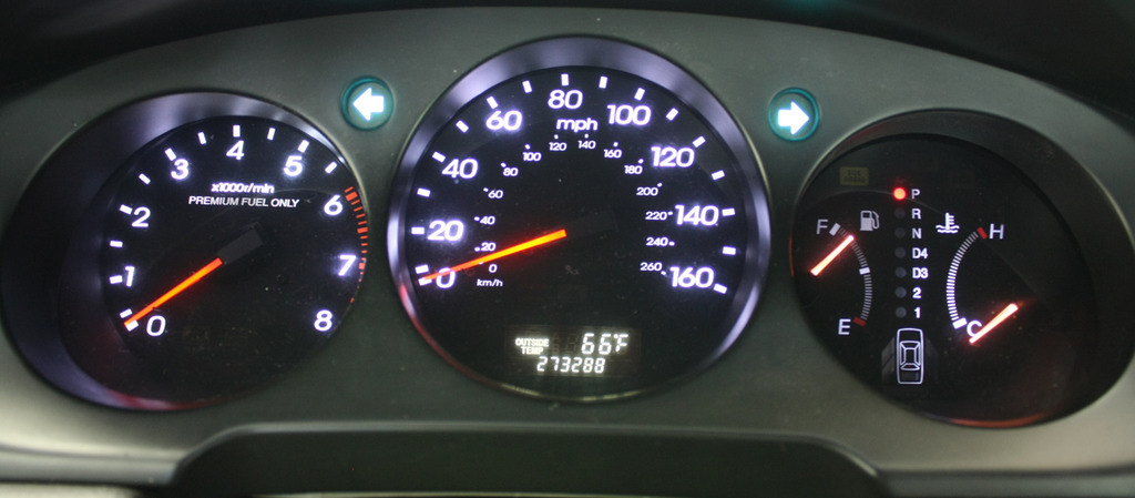
https://acurazine.com/forums/first-g...al-how-899970/
get the cluster out and onto a clean surface.
I did a thorough cleaning with Windex and put down a fresh fender cloth and used an old t-shirt to keep things and clean and dust free as possible. Having compressed air is a big plus. I bought a new frame, the PCB, the mounting parts for the speed-o & tach and some extra “wood screws”. The longer course threaded screws.

Once you have the cluster out, start by removing the white cover on the back. It’s held on by three gold screws and several snap tabs. Three of the snap tabs are under the yellow foam.


Once all the tabs are free, pull the cover off. Unplug the 2 tan connectors. Use a small blade screwdriver and start at one end and get it loose then rock it back & forth so you don’t bend the pins. If you do, use a needle nose pliers to straighten them. Be careful not to go too far and snap them off.


Unplug the ribbon cable by prying up the capture bar at both ends and pull the ribbon out of the connector.


Remove the screws from the gauges. Keep track where each one comes from. There are two different length “wood screws” and machine screws.


The board should come off the frame now. Mine had a couple pieces of double stick tape so it didn’t just come free, I had to work those spots free. Watch out for the connector from the main board to the tach board. It looks like it could easily be damaged and wouldn’t be any fun to fix. It may come apart but I've dealt with those types of connectors in other devices and they are PITA to get back together. I just held both sections and took them off as a unit.


If you previously installed LED’s, mark which side of the socket is positive. I got 1/3 of the way through when I realized I didn’t. Not a huge deal as I figured out a way to check them before reassembly and marked them after the fact for future reference. The 2 long ones are for the turn indicators. Notice the one on the right is black. It needs replaced which became an issue for me later.

This is the fuel/temp gauge section. Notice the little black dot on the board where the left most LED's goes and the white dot on the LED. They mark the positive terminals. The LED’s from Super Bright LED’s came marked so I just had to add the dot to the board. The mark by the right most LED is a piece of "stuff", not a mark. I didn't notice that when I took the pic so disregard it. If you follow the circuit it obvious which terminal is +12V and which is GND. Once I got all of them working I used a red Sharpie to mark them clearly.

At this point I noticed my assistant wasn’t around. She got bored and went back into house for a nap.

Remove the little circuit board for the door open warning lights.

Flip the cluster over and remove the black “glass” by releasing the snap tabs holding it in-place. There are snap tabs for the inner face too, so don’t confuse the two. The one on the left is for the glass, the one on the right is for the inner face.

Some are hidden under the yellow foam. Just peal back the foam and release them.

Once all are released you can remove the glass.

There are two rubber seals between the gauges. Mine were stuck to the glass, so I peeled them off and put them back on the inner frame. I could then clean the glass really good before reassembly.


At this point I would go wash my hands. The flat black inner panel is really bad for showing finger prints. I hate wearing latex gloves but that would work too. Now release all the snap tabs for the inner face. Be careful because it’s the only thing holding the actual gauges in-place.


On mine the little chrome cups on the back of the temp and fuel gauges would just fall right off. I just gave them a pinch so they were just bit oval shaped so they would stay on once reassembly began. Remove the gauges and set them aside in a safe, clean spot, and cover them so they don’t get dusty. Now remove the information display. Note: If you wanted to change the color, it would be a matter of replacing the orange lens with something of a different color. It would have to be handmade but doable for sure. Perhaps using clear Lexan with window tinting to modify the color might work.


I bought a new frame, the little gauge mounts, the PCB for the back lights and some extra long, course screws so I was ready to reassemble everything at this point. If you’re only replacing either the frame or the PCB, you’ll need to separate the two. The PCB comes of fairly easy. It’s just a matter of getting ahold of the PCB on each side of the pins and pulling it free. Go slow and don’t stretch or tear the PCB. Once out, it’s easy to clean up the contact areas with a scotch bright pad. Don’t get carried away as the copper film is pretty thin. The little gauge mounts are held in place with small screws as well as clipping into place. PITA but I got them out OK. I just needed the screws but removed them out of curiosity.

To install the new PCB on the new frame I used a �” drive, �” deep socket. It worked perfectly and fit right over the pins so I could press the PCB over each one.


Old vs New…

Assembly is just reverse of disassembly. Take your time, keep everything clean.
Now the PITA part. Once I got everything together and installed the cluster in the car. I checked that everything lit up and the gauges work. I had my car on a lift so I started it and put it in gear and let the front wheels turn enough for the speed-o show me it was working. The tach still wasn’t working so I’m not sure where it’s gone bad. It was fine when I first did the LED swaps a few years ago and assumed it was a bad connection. I fiddled with all the plugs and such but couldn’t get it to work. F-it, I can live without it. So I put everything back together only to find out that the right turn signal indicator wasn’t working. I knew when I saw the bulb all black I should replace it, but I didn’t have one so I took a chance… Bad choice!!! Oh well, I didn’t have time to tear everything back out that day and left it. I took if for a drive to check op’s on everything else and all seemed well until I hit the top of my driveway and got out onto my dirt road. I had several LED’s that started flickering. If I gave the dash a smack they would come on but I couldn’t leave it like that. A couple days later, I tore out the cluster again. Much easier when you’re not removing the center console/entertainment center. It only took 45 minutes and I had it back on the bench.First up was replacing the turn indicator bulbs with LED’s. The OEM bulbs just pull off the long sockets so I used a couple of my blue LED’s. I tried the high output ones first but they were way too bright. The standard output blues worked just fine and with the green lenses they are just a touch towards cyan in color but still green enough no one would notice without a side-by-side comparison. Next was dealing with the flickering back lights. What I finally did was I found an old 12VDC transformer from a modem or some other long gone POS. I cut the plug off and replaced it with gator clips.

I could then unplug the ribbon cable and clip the gators to it and check LED op’s on the bench. Note the red marks by the LED's for the tach. Those are the ones I didn't mark before disassembly. After I made sure everything was working solid, I marked them for future reference. All the other back lights have the positive terminal on the opposite side so it's good to mark them before removing them.


With the end up and the copper side facing you, from left to right, the pin-outs for this connector are as follows:
Tach lights_+12VDC
Tach lights_GND
Left Turn_+12VDC
Right Turn_+12VDC
Turn Indicator_GND (for both)
Speed-O, Fuel & Temp_+12VDC
Speed-O, Fuel & Temp_GND
I'm clipped to the Speed-O, Fuel & Temp gauge circuit in the pic above.
To fix the flickering, I just bent the contacts on the bulbs out a little so I had a tighter fit and therefore a better connection.

Except for the tach not happy, it’s all working and looks pretty good.

Last edited by El-Baz; 06-18-2017 at 12:07 PM. Reason: typo's
06-18-2017, 12:14 PM
#39
Advanced
Thread Starter
Join Date: Nov 2013
Location: Bailey, Colorado
Age: 64
Posts: 86
Likes: 0
Received 9 Likes
on
9 Posts
Corrected...
I added this to my cluster removal How-To, but it had so many typo's and couple mistakes I got timed out for edits (10 minutes) so I just started a new thread for this process and I'll have the admins delete the rebuild portion in the removal How-To thread.

