Acura RDX 2008 Front Strut/Shock Replacement DIY
 11-29-2012, 07:06 PM
#1
Acura RDX 2008 Front Strut/Shock Replacement DIY
Acura RDX (2008) Strut Replacement DIY
This is a DIY record of my experience replacing the front strut assemblies on a 2008 Acura RDX with new ones. This is not to be construed as professional advice and I am not a trained mechanic. If you attempt this job you do so at your own risk. You can be seriously injured and I urge you to be careful and consult professional help prior to undertaking this kind of work. This is an informational DIY only so that others may share my experience. If you have any doubts, seek help from professional mechanics.
Tools needed:
Hex head sockets of 12mm, 14mm (deep socket), 17mm, 19mm and 22mm. One 5mm Allen wrench on 3/8 inch ratchet drive or regular 5mm Allen wrench. Small width flat head screw drivers. Torque wrench and ratchet wrenches with 6 inch extension. Needle nosed pliers. Open ended box wrenches of 17mm and 19mm and a 17mm crowfoot. An impact wrench with 17mm, 19mm and 22mm (optional) impact sockets. Hydraulic floor jack and 4 jack stands capable of supporting the cars weight. Marker to mark nuts and bolts. Small blocks of wood to place underneath suspension when using hydraulic lift to raise suspension during installation of struts. U-shaped hack saw with thin blade and fine teeth! An extension magnet was also useful.
Parts needed:
Left and right strut assemblies Part# 51601-STK-A07, 51602-STK-A07. Four flange (pinch) bolts #90119_STK-A01 and four flange nuts #90382-STK-A01. Two flange (stabilizer link) nuts #94050-12080. Ten flange (damper attachment, 5 each side) nuts # 90002-S10-000. Two sensor harness clips #91507-STK-A01. Anti-seize grease, white lithium grease and Super Penetrating oil.
You will need about four hours to complete this task if you have all the required parts and tools and assuming things go smoothly with no broken parts. A knowledgeable mechanic could probably do this job in two hours, maybe less! Here is a good diagram of the strut http://www.oemacuraparts.com/parts-c...shock-absorber . That link is to the dealer in Phoenix, AZ where I purchased the parts. They also emailed me copy of some brief installation instructions in PDF format. This was quite useful as it had the removal and installation instructions with the order of task completion. There were a couple of mistakes which I figured out easy enough. The dealer�s instructions were four pages and had some nice diagrams which I highly recommend you demand from the dealer you buy your parts from.
The following links to parts diagrams might be useful when ordering parts for the strut assembly replacement:
PDF file with dealer instructions (attached file further down in this thread) for R&R of front strut assembly! My description follows this instruction set.
Before you do anything, measure the distance from the center of your wheel hub to the fender directly above with your vehicle setting on the ground normally. You will use this distance to compress the suspension before torquing the pinch bolts and damper flange bolts during the installation of the new strut assembly.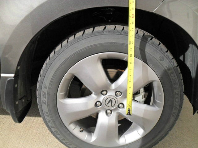
Removal
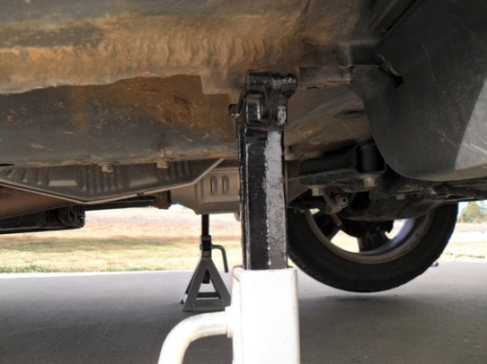
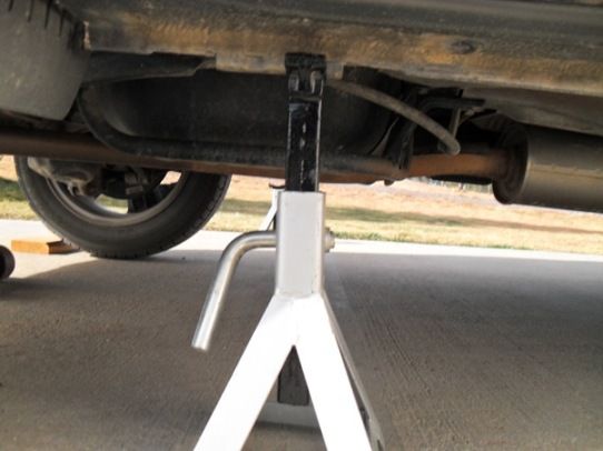
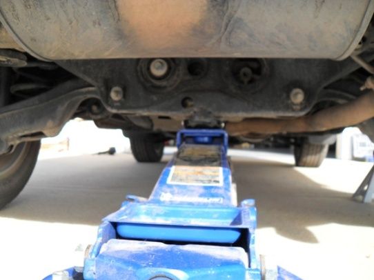
First, park the vehicle in a level area where you can work and put the car on jack stands supporting the car at the proper places on each side of the car making sure that wheels are off the ground, the car is level and that the stands won�t fall over while you are working on the front end. If you don�t know where the jack points are ask someone. You can damage your vehicle if you lift in the wrong place! Never put your body underneath the car while working just in case the car falls off of the jack stands. I placed some blocks of wood under the rear wheels to give slight support to the car and wedged some wood in front and behind tires to help keep the car from moving while I was working on it. You are going to be yanking and pulling on the vehicle while applying the tools for removal and installation. I also used a hydraulic floor jack to hold the front end up at the lift point in case the car fell off the front jack stands to prevent injury. This may be overkill but I figure it gave me more peace of mind while working.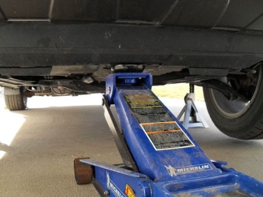
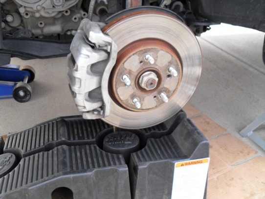
Second, remove the front wheels using your impact wrench with a 19mm socket.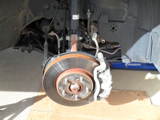
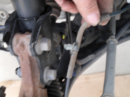
Third, remove wheel sensor harness clip, wire guide and brake hose bracket with 12mm socket from the strut assembly. Be careful not to damage the sensor harness! I used two screw drivers and needle nosed pliers to carefully remove the sensor harness clip from the strut body. This harness senses wheel speed for anti-skid and tire pressure so it is important. Place the sensor harness and brake line to the side away from your working tools and clear of the strut body. I used a u-shaped hacksaw with thin blade and fine teeth to carefully cut the old nylon harness clip from the sensor line while using needle nosed pliers to hold the nylon clip securely. Be careful!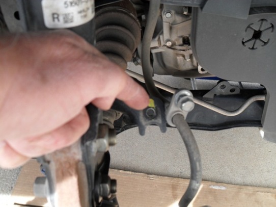
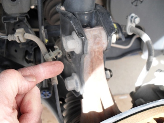
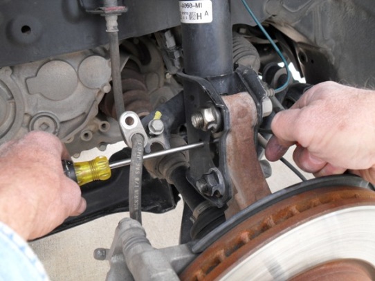
Fourth, disconnect the stabilizer link nut using a 17mm crescent wrench or crow foot and 5mm Allen wrench after soaking the bolt threads with Super Penetrating oil. I could not get the crowfoot to work here as the bracket on the strut was too confining to allow proper rotation of the crowfoot. The nut was pretty rusty and I ended up using an impact wrench to loosen the nut just enough to allow me to use a crescent wrench and Allen wrench to slowly remove the nut. I recommend a 5mm Allen on a 3/8 drive with ratchet wrench to remove the nut held with a crescent wrench. If you use those two tools, make sure you are turning the Allen wrench which is in the bolt in the correct direction to loosen it, i.e. the opposite way you would turn the nut to loosen! I was then able to remove the stabilizer link and place it to the side and out of the way for the rest of the job. I checked with my local shop mechanic and he said this is how they do it. It worked! You will notice that the stabilizer link bolt rotates and pivots in all directions. Be careful not to damage the bolt/link dust boot! I then lubed this bolts threads with anti-seize for the installation.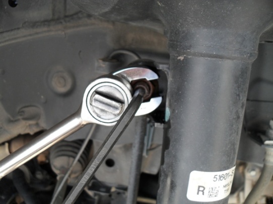
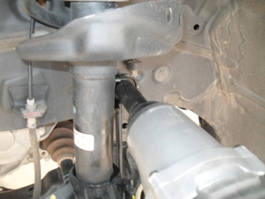
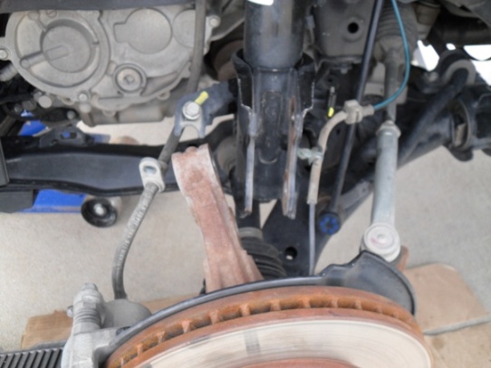
Fifth, I removed the damper pinch bolts and self-locking nuts using a 19mm impact socket/wrench on the bolt head and 22mm hex-head socket on the nut while supporting the knuckle with brake assembly on a ramp so that the heavy knuckle and brake assembly wouldn�t drop suddenly and damage the sensor and brake lines. . If the knuckle is still gripping the damper pinch bracket by friction/rust remove the knuckle and rotate it slightly rearward and downward to get it out of the way. Support the knuckle with a ramp or anything that will support its weight so that you can remove the strut later.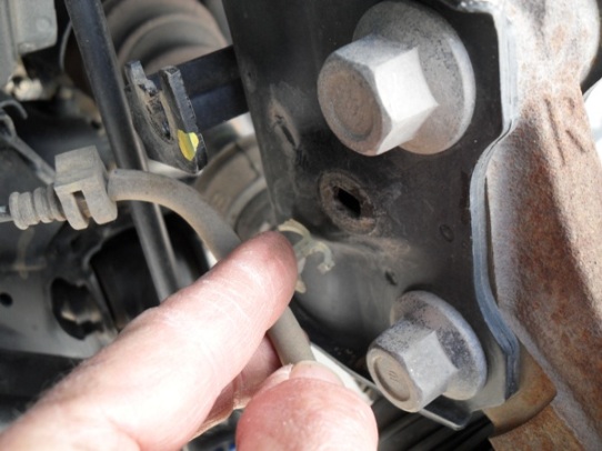
Sixth, open the hood to gain access to the cowl covers which set on either side next to the rear near the wipers. I used a small bladed screwdriver to pry them up in the pry slot of the cowl cover. Once they are cracked open, carefully lift the whole cover completely off and put it and the rubber weather stripping aside so that you can now work in that area.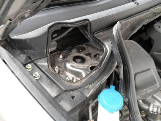
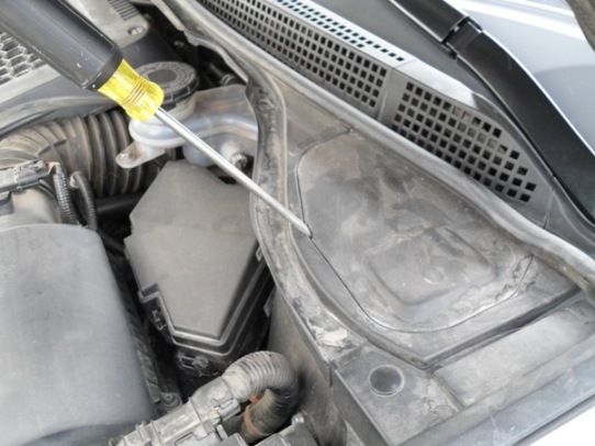
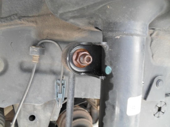
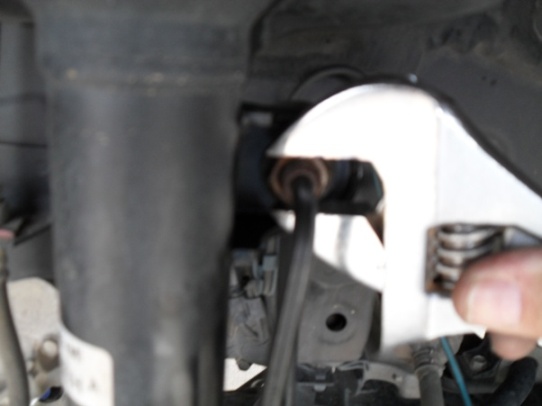
Seventh, I then removed the five flange nuts holding the damper/strut assembly with a 14mm deep socket. No extension needed if you use a deep socket plus the two longer bolts require a deep socket. You will notice three shorter bolts which will be the first ones to torque when installing the new strut assembly. I dropped a couple of the nuts in the shroud surrounding the flange bolts and had to use an extension magnet to retrieve them as my fingers wouldn�t fit into the holes. I left one nut still holding the strut weight until I positioned one hand under the fender supporting the strut assembly by holding onto the spring, then removing the last nut with the other hand.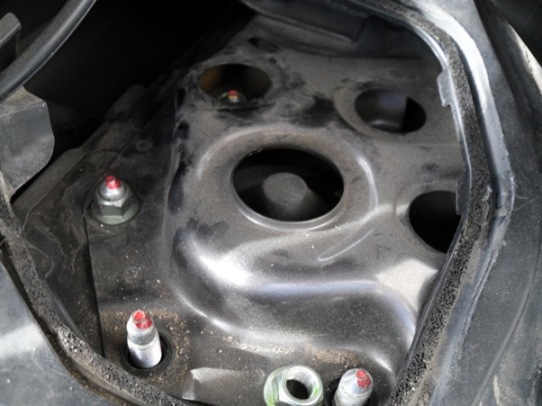
Eighth, in the wheel well, I then grabbed the strut with both hands to lower it. I found that tilting the strut bottom toward the front of the vehicle allowed me to tilt the top of the strut toward me and carefully remove the strut being very careful not to damage the brake of sensor lines. Knuckle was rotated slightly rearward and downward.
Installation
First, place the new strut /damper assembly in to the wheel well using both hands and being careful not to damage the brake or sensor lines. I was able to reverse the removal tilting to get the flange bolts on the top of the damper into their respective holes.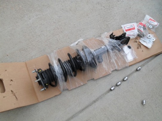
Second, loosely place the new damper flange nuts onto the damper bolts with one hand supporting the strut assembly and the other putting the nuts loosely on. I used some white lithium grease on the smooth portion of these bolts. Don�t them torque yet.
Third, loosely install the new damper pinch bolts and self-locking nuts with 19mm and 22mm wrenches. A crescent and ratchet with socket works fine here. This is a good time to check that you have the correct strut for each side by checking that the brake line bracket on the damper body is toward the front of the vehicle. J
Fourth, I connected the stabilizer link to the damper bracket being careful not to damage the bolt threads. I applied some anti-seize grease to the bolt threads and tightened the new self-locking 17mm nut using a 5mm Allen wrench to hold the bolt while tightening the nut. I don�t think it matters if you turn the nut or bolt until the nut starts to make contact with the damper bracket. Once the nut starts to get snug, and then hold bolt steady with the Allen wrench while tightening the nut. The recommended torque is 58 ft. lb. I could never figure out how to torque the nut with the tools I had available. I just tightened it down good and snug! I�m sure there is one for this job but I am not aware of it. I asked my local mechanic and he said that they also just tighten it �good and snug�. I also put a blue permanent mark on the nut and threads to indicate to me later if there was any loosening of the nut thus requiring more tightening! I will check all nuts and bolts after a few hundred miles or sooner to check for loose nuts.
Fifth, I installed the new wheel sensor harness clip in the proper orientation, the sensor wire guide (rubber piece that is re-used to hold line in damper bracket) and the brake hose bracket to the damper using a 12mm wrench.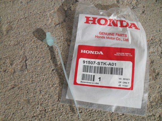
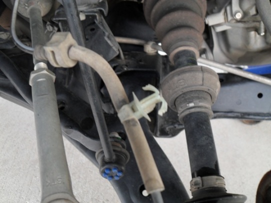
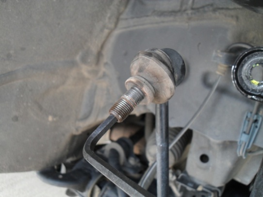
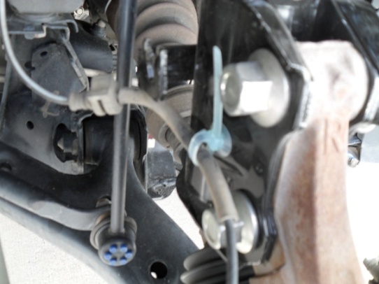 Anybody know what those little blue thingys are on the link?
Sixth, raise the front suspension with a floor jack to load the suspension with the vehicle�s weight. I did this by using some small wood blocks between the floor jack and the lower arm assembly under the ball joint where it attaches to the knuckle and there are two bolts protruding downward from the arm. I avoided putting any weight on the two protruding bolts and carefully jacked up the suspension to support the weight of the car on the suspension. I noted that the distance from the center of the wheel hub to the top of the fender edge at the wheel well as 17 � inches while the car was setting in the driveway prior to jacking the car up on the stands. I also noted that the same distance with the wheels off the ground and on the stands was 21 inches. This meant that I needed to lift the suspension up 3 � inches with the floor jack to get the proper weight load on the suspension for the remaining bolt tightening. I figured this was close enough for me.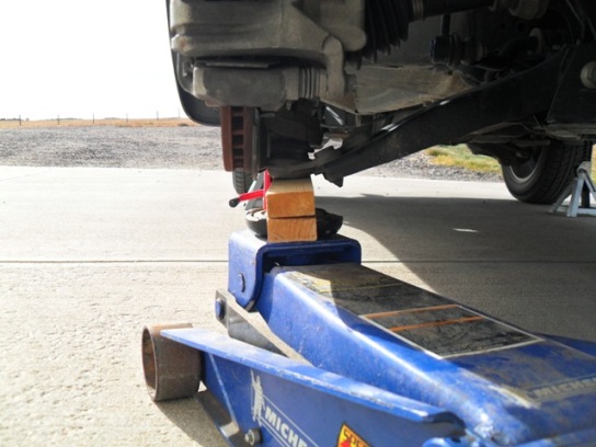
Seventh, tighten the new pinch bolts and self-locking nuts with the floor jack compressing the spring in the suspension using a 22mm socket on your torque wrench and 19mm crescent wrench on the bolt head. I didn�t use any anti-seize on these threads as the old bolts came of easily and appeared in good condition. The recommended torque is 122 ft. lb. on the pinch bolts. Mark the bolt threads and nuts with permanent marker to ensure that you can check that the nuts don�t loosen later.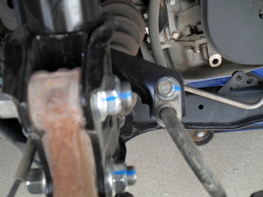
Eighth, now go back under the hood to tighten the damper flange nuts. Start with the three shorter bolts saving the two longer bolts for last. Using a 14mm deep socket and torque wrench I tightened the nuts to 33 ft. lb. tightening the three shorter bolts and lastly the two longer bolts. This step makes sure that you stagger your nut torque correctly. Mark the bolt threads and nuts with a permanent ink marker.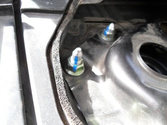
Ninth, install the cowl lid covers over the nuts that you just tightened in the last step. Re-secure the rubber weather stripping over the cowl lid.
Tenth, clean the disc brake surfaces in case you got some grease or oil on them. Re-install the front wheels and torque to 80 ft. lb.
Eleventh, check front end wheel alignment at your local shop as it has surely changed and will cause excessive tire wear if you don�t re-align your wheels.
Done! Enjoy your new smoother ride!
Also, refer to this thread for more useful information including videos on doing this job if you are replacing the damper only and need to compress the spring. https://acurazine.com/forums/1g-rdx-tires-wheels-suspension-362/monroe-front-struts-866488/
This is a DIY record of my experience replacing the front strut assemblies on a 2008 Acura RDX with new ones. This is not to be construed as professional advice and I am not a trained mechanic. If you attempt this job you do so at your own risk. You can be seriously injured and I urge you to be careful and consult professional help prior to undertaking this kind of work. This is an informational DIY only so that others may share my experience. If you have any doubts, seek help from professional mechanics.
Tools needed:
Hex head sockets of 12mm, 14mm (deep socket), 17mm, 19mm and 22mm. One 5mm Allen wrench on 3/8 inch ratchet drive or regular 5mm Allen wrench. Small width flat head screw drivers. Torque wrench and ratchet wrenches with 6 inch extension. Needle nosed pliers. Open ended box wrenches of 17mm and 19mm and a 17mm crowfoot. An impact wrench with 17mm, 19mm and 22mm (optional) impact sockets. Hydraulic floor jack and 4 jack stands capable of supporting the cars weight. Marker to mark nuts and bolts. Small blocks of wood to place underneath suspension when using hydraulic lift to raise suspension during installation of struts. U-shaped hack saw with thin blade and fine teeth! An extension magnet was also useful.
Parts needed:
Left and right strut assemblies Part# 51601-STK-A07, 51602-STK-A07. Four flange (pinch) bolts #90119_STK-A01 and four flange nuts #90382-STK-A01. Two flange (stabilizer link) nuts #94050-12080. Ten flange (damper attachment, 5 each side) nuts # 90002-S10-000. Two sensor harness clips #91507-STK-A01. Anti-seize grease, white lithium grease and Super Penetrating oil.
You will need about four hours to complete this task if you have all the required parts and tools and assuming things go smoothly with no broken parts. A knowledgeable mechanic could probably do this job in two hours, maybe less! Here is a good diagram of the strut http://www.oemacuraparts.com/parts-c...shock-absorber . That link is to the dealer in Phoenix, AZ where I purchased the parts. They also emailed me copy of some brief installation instructions in PDF format. This was quite useful as it had the removal and installation instructions with the order of task completion. There were a couple of mistakes which I figured out easy enough. The dealer�s instructions were four pages and had some nice diagrams which I highly recommend you demand from the dealer you buy your parts from.
The following links to parts diagrams might be useful when ordering parts for the strut assembly replacement:
PDF file with dealer instructions (attached file further down in this thread) for R&R of front strut assembly! My description follows this instruction set.
Before you do anything, measure the distance from the center of your wheel hub to the fender directly above with your vehicle setting on the ground normally. You will use this distance to compress the suspension before torquing the pinch bolts and damper flange bolts during the installation of the new strut assembly.
Removal
First, park the vehicle in a level area where you can work and put the car on jack stands supporting the car at the proper places on each side of the car making sure that wheels are off the ground, the car is level and that the stands won�t fall over while you are working on the front end. If you don�t know where the jack points are ask someone. You can damage your vehicle if you lift in the wrong place! Never put your body underneath the car while working just in case the car falls off of the jack stands. I placed some blocks of wood under the rear wheels to give slight support to the car and wedged some wood in front and behind tires to help keep the car from moving while I was working on it. You are going to be yanking and pulling on the vehicle while applying the tools for removal and installation. I also used a hydraulic floor jack to hold the front end up at the lift point in case the car fell off the front jack stands to prevent injury. This may be overkill but I figure it gave me more peace of mind while working.
Second, remove the front wheels using your impact wrench with a 19mm socket.
Third, remove wheel sensor harness clip, wire guide and brake hose bracket with 12mm socket from the strut assembly. Be careful not to damage the sensor harness! I used two screw drivers and needle nosed pliers to carefully remove the sensor harness clip from the strut body. This harness senses wheel speed for anti-skid and tire pressure so it is important. Place the sensor harness and brake line to the side away from your working tools and clear of the strut body. I used a u-shaped hacksaw with thin blade and fine teeth to carefully cut the old nylon harness clip from the sensor line while using needle nosed pliers to hold the nylon clip securely. Be careful!
Fourth, disconnect the stabilizer link nut using a 17mm crescent wrench or crow foot and 5mm Allen wrench after soaking the bolt threads with Super Penetrating oil. I could not get the crowfoot to work here as the bracket on the strut was too confining to allow proper rotation of the crowfoot. The nut was pretty rusty and I ended up using an impact wrench to loosen the nut just enough to allow me to use a crescent wrench and Allen wrench to slowly remove the nut. I recommend a 5mm Allen on a 3/8 drive with ratchet wrench to remove the nut held with a crescent wrench. If you use those two tools, make sure you are turning the Allen wrench which is in the bolt in the correct direction to loosen it, i.e. the opposite way you would turn the nut to loosen! I was then able to remove the stabilizer link and place it to the side and out of the way for the rest of the job. I checked with my local shop mechanic and he said this is how they do it. It worked! You will notice that the stabilizer link bolt rotates and pivots in all directions. Be careful not to damage the bolt/link dust boot! I then lubed this bolts threads with anti-seize for the installation.
Fifth, I removed the damper pinch bolts and self-locking nuts using a 19mm impact socket/wrench on the bolt head and 22mm hex-head socket on the nut while supporting the knuckle with brake assembly on a ramp so that the heavy knuckle and brake assembly wouldn�t drop suddenly and damage the sensor and brake lines. . If the knuckle is still gripping the damper pinch bracket by friction/rust remove the knuckle and rotate it slightly rearward and downward to get it out of the way. Support the knuckle with a ramp or anything that will support its weight so that you can remove the strut later.
Sixth, open the hood to gain access to the cowl covers which set on either side next to the rear near the wipers. I used a small bladed screwdriver to pry them up in the pry slot of the cowl cover. Once they are cracked open, carefully lift the whole cover completely off and put it and the rubber weather stripping aside so that you can now work in that area.
Seventh, I then removed the five flange nuts holding the damper/strut assembly with a 14mm deep socket. No extension needed if you use a deep socket plus the two longer bolts require a deep socket. You will notice three shorter bolts which will be the first ones to torque when installing the new strut assembly. I dropped a couple of the nuts in the shroud surrounding the flange bolts and had to use an extension magnet to retrieve them as my fingers wouldn�t fit into the holes. I left one nut still holding the strut weight until I positioned one hand under the fender supporting the strut assembly by holding onto the spring, then removing the last nut with the other hand.
Eighth, in the wheel well, I then grabbed the strut with both hands to lower it. I found that tilting the strut bottom toward the front of the vehicle allowed me to tilt the top of the strut toward me and carefully remove the strut being very careful not to damage the brake of sensor lines. Knuckle was rotated slightly rearward and downward.
Installation
First, place the new strut /damper assembly in to the wheel well using both hands and being careful not to damage the brake or sensor lines. I was able to reverse the removal tilting to get the flange bolts on the top of the damper into their respective holes.
Second, loosely place the new damper flange nuts onto the damper bolts with one hand supporting the strut assembly and the other putting the nuts loosely on. I used some white lithium grease on the smooth portion of these bolts. Don�t them torque yet.
Third, loosely install the new damper pinch bolts and self-locking nuts with 19mm and 22mm wrenches. A crescent and ratchet with socket works fine here. This is a good time to check that you have the correct strut for each side by checking that the brake line bracket on the damper body is toward the front of the vehicle. J
Fourth, I connected the stabilizer link to the damper bracket being careful not to damage the bolt threads. I applied some anti-seize grease to the bolt threads and tightened the new self-locking 17mm nut using a 5mm Allen wrench to hold the bolt while tightening the nut. I don�t think it matters if you turn the nut or bolt until the nut starts to make contact with the damper bracket. Once the nut starts to get snug, and then hold bolt steady with the Allen wrench while tightening the nut. The recommended torque is 58 ft. lb. I could never figure out how to torque the nut with the tools I had available. I just tightened it down good and snug! I�m sure there is one for this job but I am not aware of it. I asked my local mechanic and he said that they also just tighten it �good and snug�. I also put a blue permanent mark on the nut and threads to indicate to me later if there was any loosening of the nut thus requiring more tightening! I will check all nuts and bolts after a few hundred miles or sooner to check for loose nuts.
Fifth, I installed the new wheel sensor harness clip in the proper orientation, the sensor wire guide (rubber piece that is re-used to hold line in damper bracket) and the brake hose bracket to the damper using a 12mm wrench.
Anybody know what those little blue thingys are on the link?Sixth, raise the front suspension with a floor jack to load the suspension with the vehicle�s weight. I did this by using some small wood blocks between the floor jack and the lower arm assembly under the ball joint where it attaches to the knuckle and there are two bolts protruding downward from the arm. I avoided putting any weight on the two protruding bolts and carefully jacked up the suspension to support the weight of the car on the suspension. I noted that the distance from the center of the wheel hub to the top of the fender edge at the wheel well as 17 � inches while the car was setting in the driveway prior to jacking the car up on the stands. I also noted that the same distance with the wheels off the ground and on the stands was 21 inches. This meant that I needed to lift the suspension up 3 � inches with the floor jack to get the proper weight load on the suspension for the remaining bolt tightening. I figured this was close enough for me.
Seventh, tighten the new pinch bolts and self-locking nuts with the floor jack compressing the spring in the suspension using a 22mm socket on your torque wrench and 19mm crescent wrench on the bolt head. I didn�t use any anti-seize on these threads as the old bolts came of easily and appeared in good condition. The recommended torque is 122 ft. lb. on the pinch bolts. Mark the bolt threads and nuts with permanent marker to ensure that you can check that the nuts don�t loosen later.
Eighth, now go back under the hood to tighten the damper flange nuts. Start with the three shorter bolts saving the two longer bolts for last. Using a 14mm deep socket and torque wrench I tightened the nuts to 33 ft. lb. tightening the three shorter bolts and lastly the two longer bolts. This step makes sure that you stagger your nut torque correctly. Mark the bolt threads and nuts with a permanent ink marker.
Ninth, install the cowl lid covers over the nuts that you just tightened in the last step. Re-secure the rubber weather stripping over the cowl lid.
Tenth, clean the disc brake surfaces in case you got some grease or oil on them. Re-install the front wheels and torque to 80 ft. lb.
Eleventh, check front end wheel alignment at your local shop as it has surely changed and will cause excessive tire wear if you don�t re-align your wheels.
Done! Enjoy your new smoother ride!
Also, refer to this thread for more useful information including videos on doing this job if you are replacing the damper only and need to compress the spring. https://acurazine.com/forums/1g-rdx-tires-wheels-suspension-362/monroe-front-struts-866488/
Last edited by RangeRider49er; 11-29-2012 at 07:19 PM. Reason: Remove picture numbers.
 11-30-2012, 09:39 AM
#2
The following links to parts diagrams might be useful when ordering parts for the strut assembly replacement:
PDF with dealer instructions for R&R of front strut assembly! My description follows this instruction set in attached file. Note that on p.4 they refer to nuts A&B in step 8 when I think they meant B&C in the diagram on p.3 step 2 of Installation!
Knuckle diagram(sensor wire harness) http://www.oemacuraparts.com/parts-c...hassis/knuckle
Engine Hood (Cowl lid) http://www.oemacuraparts.com/parts-catalog/acura/rdx/2008/5dr-tech/ka5at/body-air-conditioning/engine-hood
Last edited by RangeRider49er; 11-30-2012 at 09:44 AM. Reason: Add comments on pdf file
12-02-2012, 03:32 PM
#3
haole kama'a-ina
Nice post RangeRider.
I just came across a new tool kit that makes turning the stabilizer link nuts easy as can be. Harbor Freight item 67974 is an open "go-through" socket set.
http://www.harborfreight.com/21-piece-saemetric-go-thru-socket-set-67974.html
Right now it's on sale for $20 and I used a 20% coupon to get it for $16. That is just ridiculously cheap and one always has to be careful with HF stuff, but this set is very nice. The ratchet is quiet and smooth and everything is polished chrome. It's got 10 metric sockets in all the useful sizes and I expect to get great service from it.
The following 3 users liked this post by 737 Jock:
The following users liked this post:
JCash23 (04-01-2022)
12-03-2012, 08:38 AM
#5
Nice!
Those look like some nice tools GuppyJock so I ordered some also! Thanks for the tip! I am still wondering if anyone can tell me how to properly torque the stabilizer link nut and just what are those six little blue thingeys on each end of the stabilizer link?
Thanks for the tip! I am still wondering if anyone can tell me how to properly torque the stabilizer link nut and just what are those six little blue thingeys on each end of the stabilizer link?
12-03-2012, 12:34 PM
#6
haole kama'a-ina
Now consider your typical torque wrench. It's about the size of a breaker bar and it has no "feel". Using a torque wrench on small fasteners runs the risk of snapping them off, because of the long lever arm and no sense of tightness until it clicks, or snaps the bolt.
Even if you could rig a torque wrench on the stab link nuts, you run the risk of breaking them off. Just learn to run small fasteners down to metal contact, then "bump" them a couple times with a proper size wrench, until they are tight. It should not be too much more than about 1/4 turn.
When tightening with a ratchet, always remember that it is sized for the largest socket in the set. Think about the length of a box wrench for the small sockets and "choke up".
This also aids shops, who usually don't waste 30 minutes trying to undo rusted stab links -- they just cut them off in seconds (and sell you new ones).
To cut it off, chisel off the blue plastic rivets and pull the link off. Then pull off the ball socket and hold the ball with vice grips while cutting through the shaft.
Here's a pic of a Honda stab link taken apart. You can see where the rivets have been cut off:
Last edited by 737 Jock; 12-03-2012 at 12:47 PM.
The following 2 users liked this post by 737 Jock:
dcmodels (12-04-2012),
RangeRider49er (12-04-2012)
12-03-2012, 01:42 PM
#7
Cool!
Thanks 737 Jock! I appreciate your explaining this for me and now I know. I hope I don't have to cut any off ever. Nice picture! Your description of the proper way to tighten the stabilizer link nut is essentially what I ended up doing. After snugging, I just gave it a bit more until tight! Good & tight! Thanks for the insight on this. Great picture of the stabilizer link bolt dissected. This does beg the question of just why does Honda/Acura specify a torque value for this nut? Mine came off instantly with just one hit from an impact wrench after I had soaked the threads in penetrating oil.
I have asked the admin if I can edit my original post on this thread to update with bigger/clearer pictures. Hopefully he will let me do it. I also got an account with PhotoBucket to upload the bigger pictures if the admin allows me to edit an older post! They are ready to go if I get the green light! Cheers!
I have asked the admin if I can edit my original post on this thread to update with bigger/clearer pictures. Hopefully he will let me do it. I also got an account with PhotoBucket to upload the bigger pictures if the admin allows me to edit an older post! They are ready to go if I get the green light! Cheers!
Last edited by RangeRider49er; 12-03-2012 at 01:48 PM. Reason: Add question on torque. Add comment on impact wrench.
Trending Topics
12-04-2012, 02:43 AM
#8
HOW TO TORQUE THE STABILIZER LINKS
Torque is specified for the same reason it is always done - to make certain it is tight enough but not too tight. And it is only 29 ft-lbs which is the same as the engine drain plug, so no surprise it 'released' instantly. The reason the engine drain plug will not release is because the aluminum washer has galled (cold welded) to both the plug and the oil pan. There is no similar problem with the stabilizer link nuts.
In the interest of disclosure, I have not removed nor replaced the link nuts. But the FSM has a picture which shows how to properly use a torque wrench, with a crow's foot flare nut wrench extension on the torque wrench, and the center bolt held with a metric hex Allen wrench.
Much easier than torquing the engine barrel base nuts on a 750 Norton (motorcycle), which required me to have a welder build me the proper torque wrench extensions.
And please, do not use a normal open-end crow-foot extension, for the same reason you do not use a normal open-end wrench when you can use the closed end of the wrench. It reduces the likely hood of rounding off the nut flats. And although you will probably not find one, do NOT use a 12-point flare-nut extension, only the 6-point type, for the same reason.
Sorry, but I am too lazy to reproduce the FSM picture.
But Sears sells crow-foot flare nut extensions. It is just basically the end of a flare-nut wrench, with a 3/8 inch square socket (opening) to accept the drive end of a 3/8 inch drive torque wrench. These crow-foot extensions are specifically meant to be used with a torque wrench, just as shown in the FSM (factory service manual).
I would hold the center of the bolt with a hex drive extension in a ratchet wrench, instead of a hex-key, because it would provide greater control and torque holding while you tighten the nut.
As for the wrench, yes, using a 50-pound wrench might present some clearance problems. And do not be using a 100-pound wrench, or alas, a 150-pound wrench - that would be very bad, and not give you valid readings.
I have 3 torque wrenchs for that reason: 15-pound, 50-pound, and 150-pound beam type wrenches.
I again confess I have not performed this maintenance. But for me, 29 ft-lbs is difficult to judge using only a 8-10 inch long wrench. Maybe I am old (yes) and weak (again, yes), but I have tried that before and find a torque wrench necessary for a valid torque.
One last thing - THE TORQUE ON THE WRENCH MUST BE ADJUSTED, to account for the extension of the crow-foot. If the torque wrench is attached at 90 degrees to the crow-foot, no adjustment is required. I hope that statement is clear.
If the torque wrench is attached to the crow-foot, so that both are in alignment, then the torque must be decreased by the length of the crow-foot.
That means, for example, say that the distance from the CENTER of the crow-foot opening to the CENTER of the 3/8 drive opening is 1-inch. And say that the length of the torque wrench is 12-inches.
Then the torque to be used is 12 / (12 + 1) = 0.923 * 29 = 26.8 ft-lbs
I hope that this helps.
The following users liked this post:
RangeRider49er (12-04-2012)
12-04-2012, 02:58 AM
#9
TORQUE CORRECTION & link nut replacement REQUIREMENT
I just noticed that the torque specification for my 2009 FRONT sway-bar links is 58 ft-lbs. If possible, I would use a 100-pound torque wrench. A torque wrench reads the most accurately in the middle of the range, and is considered inaccurate at the lower and top 20% of the range.
The REAR bar-links torque specification is 29 ft-lbs.
The difference is because the FRONTS are 12mm bolts, and the REARs are 10mm bolts, and sorry I did not note this in my previous post. And I hope that your 2007 RDX has the same torque specifications, but it might be a good idea to check.
ALSO: my FSM says to REPLACE THE LINK NUTS.
FINAL NOTE: my FSM says there is a white paint mark on the link rod, which should be positioned facing inward (toward the center of the vehicle I presume).
Last edited by dcmodels; 12-04-2012 at 03:09 AM.
The following users liked this post:
RangeRider49er (12-04-2012)
12-04-2012, 03:36 PM
#10
Thanks!
HOW TO TORQUE THE STABILIZER LINKS
In the interest of disclosure, I have not removed nor replaced the link nuts. But the FSM has a picture which shows how to properly use a torque wrench, with a crow's foot flare nut wrench extension on the torque wrench, and the center bolt held with a metric hex Allen wrench.
I used the crow foot depicted in the instructions in the pdf file I included in post #2 and I couldn't get enough room to rotate the crow's foot more than a few degrees!
And please, do not use a normal open-end crow-foot extension, for the same reason you do not use a normal open-end wrench when you can use the closed end of the wrench. It reduces the likely hood of rounding off the nut flats.
I used it and it still started rounding off the edges!
But Sears sells crow-foot flare nut extensions. It is just basically the end of a flare-nut wrench, with a 3/8 inch square socket (opening) to accept the drive end of a 3/8 inch drive torque wrench. These crow-foot extensions are specifically meant to be used with a torque wrench, just as shown in the FSM (factory service manual).
Got mine at NAPA! It looks just like the one in the pictures of the pdf file from the dealer.
I would hold the center of the bolt with a hex drive extension in a ratchet wrench, instead of a hex-key, because it would provide greater control and torque holding while you tighten the nut.
Yep, that's what I did.
I hope that this helps.
12-04-2012, 08:00 PM
#11
Crow Foot Flare Nut Wrench
dcmodels:
This may be the only wrench I can find that will allow you to torque this particular stabilizer link nut due to the damper body bracket interfering with the wrench. I looked on line and can't find anything in this style except 12 point. Even this style would probably limit your turn to 15-20 degrees of rotation without re-seating the wrench for the next turn of the wrench. That might be enough though. Let me know if you find a wrench that will work.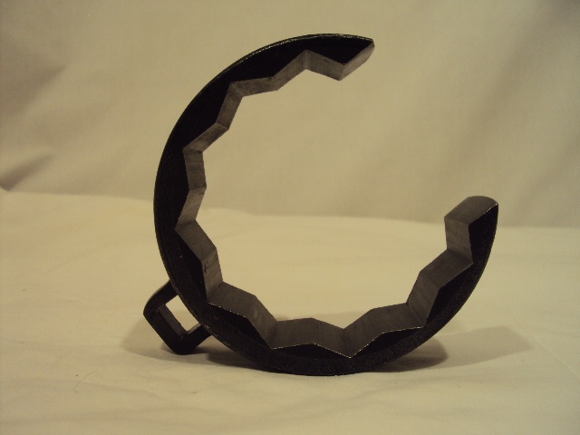
This may be the only wrench I can find that will allow you to torque this particular stabilizer link nut due to the damper body bracket interfering with the wrench. I looked on line and can't find anything in this style except 12 point. Even this style would probably limit your turn to 15-20 degrees of rotation without re-seating the wrench for the next turn of the wrench. That might be enough though. Let me know if you find a wrench that will work.
12-04-2012, 10:05 PM
#12
^^^ ??
Well, actually it seems like what I suggested really did not help much if at all. I do appreciate your response, as it means that there are some problems I am going to have when I try this.
I was rotating my tires this afternoon, and I can see that the top link mount to the strut body has a flange which likely is preventing you from turning the crow-foot - and I think that is what you are saying.
The picture that you have posted, is first of all a 12-point which is more likely to round the corners of the nut. And the 'ring' slot-opening is likely to allow the crow-foot to 'open' at the very high torque of 58-pounds. The same configuration, with a completely closed 'ring', might work. I am uncertain if such a tool exists.
The crow-foot in the pic in the FSM has 'reinforced' sides for that very reason, to prevent spreading of the sides, and I assume is also the reason why it don't fit with the strut-flange in the way.
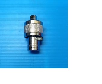
As for the bottom link nut, there is a ratcheting extension that can be used on a torque wrench. A picture would help here, but I do not have one, nor access to a camera to take a pic of my own tool. This is basically the ratchet mechanism from a ratchet wrench, with a female 3/8 inch drive on one end, and a male 3/8 inch drive on the other end, with the ratcheting mechanism in the middle. Length is about 1.5 inches, and allows the torque wrench to act like a ratcheting 3/8 drive.
I really do not know if this ratchet extension would help with the (bottom) sway-bar link nut, but it sure helps me with with drain plugs and other bolts & nuts in tight places that I want to torque.
I am uncertain about your reference here, but if you are saying you used the closed end of a combination wrench (and not the crow-foot), then be aware that there are combi-wrenches with 6-point ends, instead of the usual 12-point ends.
There are also differences in 12-point combi-wrenches: some actually fit, and will not round the nut corners. Most all of my tools are Sears or cheaper, except when I need it to really count, and then I have a few Snap-Ons.
I can offer only one other suggestion. Round off 58-pounds to 60-pounds. Use your torque wrench to torgue a wheel nut to 60 poinds. Or actually, use a combi-wrench to pull what you think is 60 pounds. Then 'check-it' with your 150 pound torque wrench. That is, check how much torque is required to pull the wheel nut slightly tighter. Try it a couple or three times.
Then use the same combi-wrench to tighten the sway bar link ends., trying for the same 'feel'. Note that the FSM states torque settings for DRY and CLEAN assembled fasteners.
Then use the GREEN version of LOCK-TITE, which is to be applied to assembled nut-bolts. It seeps into the threads, and locks them about the same as using the BLUE version.
Since I am not as strong as I once was, I would do the above, only I would perform the entire procedure at 40-pounds. And then I would torque the sway-bar link nuts with BLUE thread lock on the threads. I often use this technique, with the thread-lock, and reduce the torque by 20%. The thread-lock is a pretty good lubricant.
Well, actually it seems like what I suggested really did not help much if at all. I do appreciate your response, as it means that there are some problems I am going to have when I try this.
I was rotating my tires this afternoon, and I can see that the top link mount to the strut body has a flange which likely is preventing you from turning the crow-foot - and I think that is what you are saying.
The picture that you have posted, is first of all a 12-point which is more likely to round the corners of the nut. And the 'ring' slot-opening is likely to allow the crow-foot to 'open' at the very high torque of 58-pounds. The same configuration, with a completely closed 'ring', might work. I am uncertain if such a tool exists.
The crow-foot in the pic in the FSM has 'reinforced' sides for that very reason, to prevent spreading of the sides, and I assume is also the reason why it don't fit with the strut-flange in the way.
As for the bottom link nut, there is a ratcheting extension that can be used on a torque wrench. A picture would help here, but I do not have one, nor access to a camera to take a pic of my own tool. This is basically the ratchet mechanism from a ratchet wrench, with a female 3/8 inch drive on one end, and a male 3/8 inch drive on the other end, with the ratcheting mechanism in the middle. Length is about 1.5 inches, and allows the torque wrench to act like a ratcheting 3/8 drive.
I really do not know if this ratchet extension would help with the (bottom) sway-bar link nut, but it sure helps me with with drain plugs and other bolts & nuts in tight places that I want to torque.
And please, do not use a normal open-end crow-foot extension, for the same reason you do not use a normal open-end wrench when you can use the closed end of the wrench. It reduces the likely hood of rounding off the nut flats.
I used it and it still started rounding off the edges!
I used it and it still started rounding off the edges!
There are also differences in 12-point combi-wrenches: some actually fit, and will not round the nut corners. Most all of my tools are Sears or cheaper, except when I need it to really count, and then I have a few Snap-Ons.
I can offer only one other suggestion. Round off 58-pounds to 60-pounds. Use your torque wrench to torgue a wheel nut to 60 poinds. Or actually, use a combi-wrench to pull what you think is 60 pounds. Then 'check-it' with your 150 pound torque wrench. That is, check how much torque is required to pull the wheel nut slightly tighter. Try it a couple or three times.
Then use the same combi-wrench to tighten the sway bar link ends., trying for the same 'feel'. Note that the FSM states torque settings for DRY and CLEAN assembled fasteners.
Then use the GREEN version of LOCK-TITE, which is to be applied to assembled nut-bolts. It seeps into the threads, and locks them about the same as using the BLUE version.
Since I am not as strong as I once was, I would do the above, only I would perform the entire procedure at 40-pounds. And then I would torque the sway-bar link nuts with BLUE thread lock on the threads. I often use this technique, with the thread-lock, and reduce the torque by 20%. The thread-lock is a pretty good lubricant.
Last edited by dcmodels; 12-04-2012 at 10:08 PM.
12-05-2012, 11:38 AM
#14
I still don't get it! Sorry.
^^^ ??
I was rotating my tires this afternoon, and I can see that the top link mount to the strut body has a flange which likely is preventing you from turning the crow-foot - and I think that is what you are saying.
Yes!
The picture that you have posted, is first of all a 12-point which is more likely to round the corners of the nut. And the 'ring' slot-opening is likely to allow the crow-foot to 'open' at the very high torque of 58-pounds. The same configuration, with a completely closed 'ring', might work. I am uncertain if such a tool exists.
That is the only picture I could find to readily post and I think I noted that! Are you reading my posts? I also specified the proper torque for the stab link nut in my initial post. You caught your own mistake at least. I also remade the initial post with better pictures so you might take a look at it if you have time.
The crow-foot in the pic in the FSM has 'reinforced' sides for that very reason, to prevent spreading of the sides, and I assume is also the reason why it don't fit with the strut-flange in the way.
Yes! See first post picture of link nut! Also, see the attached pdf file in post #2 dealer-provided instructions with picture of crows foot on ratchet wrench.
As for the bottom link nut, there is a ratcheting extension that can be used on a torque wrench. A picture would help here, but I do not have one, nor access to a camera to take a pic of my own tool. This is basically the ratchet mechanism from a ratchet wrench, with a female 3/8 inch drive on one end, and a male 3/8 inch drive on the other end, with the ratcheting mechanism in the middle. Length is about 1.5 inches, and allows the torque wrench to act like a ratcheting 3/8 drive.
Okay, one more tool needed!
I am uncertain about your reference here, but if you are saying you used the closed end of a combination wrench (and not the crow-foot), then be aware that there are combi-wrenches with 6-point ends, instead of the usual 12-point ends.
Yep, awareness is developing and previously noted.
I can offer only one other suggestion. Round off 58-pounds to 60-pounds. Use your torque wrench to torgue a wheel nut to 60 poinds. Or actually, use a combi-wrench to pull what you think is 60 pounds. Then 'check-it' with your 150 pound torque wrench. That is, check how much torque is required to pull the wheel nut slightly tighter. Try it a couple or three times.
Good & tight? Yah?
Then use the same combi-wrench to tighten the sway bar link ends., trying for the same 'feel'. Note that the FSM states torque settings for DRY and CLEAN assembled fasteners.
Yes, good point. That is assuming new, clean bolts and nuts? Since I am keeping the same stabilizer link with rusty bolt threads, I am not sure how valid any torque setting would be. Remember, these are all self-locking nuts that should be new ones as noted in the previous post. I like 737 Jock's suggestion that you snug the nut and then put another 1/4 turn on it.
Then use the GREEN version of LOCK-TITE, which is to be applied to assembled nut-bolts. It seeps into the threads, and locks them about the same as using the BLUE version.
Maybe lock-tite is a good idea but I figure the part will just rust tight again!
Since I am not as strong as I once was, I would do the above, only I would perform the entire procedure at 40-pounds. And then I would torque the sway-bar link nuts with BLUE thread lock on the threads. I often use this technique, with the thread-lock, and reduce the torque by 20%. The thread-lock is a pretty good lubricant.
Wait, first green then blue lock-tite? Let me ask you this question. Is the reduction in friction of the lock-tite roughly equivalent to the reduction in friction of anti-seize?
12-06-2012, 01:28 AM
#15
Sorry, I may not be capable of giving good and clear directions. I will try to explain a couple of my comments/ points that you have asked about. And I realize you have already complete this repair.
I looked at your updated pictures � nice. After looking carefully at my own vehicle, there may not be a specific tool, a crow-foot, that will fit. Do note that the SK and Snap-On crow-foot wrenches seem to have �thinner� sides, although still generally shaped like the one in your DIY pictures. But a single Snap-On wrench may cost as much as the entire set you purchased.
I did not realize that the bar-link nuts are lock-nuts, even after looking at the ones on my car. But I still generally use Blue thread-lock on most everything, just to prevent the parts from rusting together � see below.
USING LOCK-TITE:
Use either GREEN or BLUE thread-lock, not both.
Lock-tite is a brand name for thread lock, which is available from various different makers/ vendors. GREEN is applied AFTER fastener assembly. It allows torquing dry fasteners, and then is applied to the assembly. It will �wick� into the threads, as it is super thin.
Also nice for use when you just want to �lock� a bunch of fasteners, but do not want to disassemble them, to use the BLUE stuff. The OEM car manufacturer does not generally use LOCK-TITE when they build your car. So you can lock all of the existing fasteners, without disassembling your car. Must be applied only to clean fasteners, not rusted 10 year old ones, although I have done it �well better than nothing. See below for how to clean fasteners, after disassembly.
BLUE thread lock is applied BEFORE fastener assembly. It will act as a lubricant, so that the torque specification must be decreased, else the fasteners will be too tight (and possibly break). I usually decrease torque spec by 20%.
ANTI-SEIZE and FASTENERS:
It is almost impossible to obtain a valid torque using anti-seize. And if a valid torque is not obtained, then the fastener may loosen, especially with anti-seize on it.
When using anti-seize I generally decrease torque by 40-50%. It really depends upon the size of the bolt/ nut pair and the type of anti-seize. But anti-seize and torque is a long topic, so only a few comments �
Actually I (almost) never use anti-seize anymore, as I have learned that it is just too difficult to get a valid torque, relative to the specified torque, and I have broken bolts trying.
Besides, I really do not know if there is ever a time that anti-seize should be used when torquing a bolt, unless you are using ARP bolts, which are intended to be torqued ONLY when using anti-seize, using the specific anti-seize sold with the bolts.
Or unless the manufacturer SPECIFICALLY RECOMMENDS THE USE OF ANTI-SEIZE DURING ASSEMBLY. The only time of which I am aware that any car maker does that, is the installation of O2 sensors in the exhaust system.
So, I say again, I strongly recommend against torquing any bolt/ nut with anti-seize. Depending upon where the anti-seize is applied, it will greatly affect the torque actually applied: on the threads only, or under the head as well. This can affect the actual torque by 100%
Either GREEN or BLUE thread-lock will prevent the threads from rusting, where it is located in the assembled fastener-pair. It is essentially a anaerobic epoxy (hey, I am not a chemist) J
You can apply anti-seize to the exposed threads if you like � and that is what I do, so that I can disassemble later, especially on an exhaust system fasteners.
CLEANING RUSTED FASTENERS:
Well, you say that you are reassembling rusted fasteners. First clean every thing with either water and soap, or spray brake cleaner, or MAP cleaner. Then use a wire brush on the rusted bolt threads. And that is why the FSM requires replacement of the nuts, because you cannot clean the threads. Finally, clean with electronic or MAP spray, which will leave no residue to affect the torque � nice and clean parts.
Also, most thread-lock makers sell both a cleaner and a primer for use before using the thread-lock. I have never used it, just the procedure above. The primer allows the thread-lock to set in a few minutes, rather than overnight.
APPLYING TORQUE WITHOUT A TORQUE WRENCH:
Yes, I am suggesting that you do that, but practice to determine what 60-ft/lbs �feels� like. You can do that by practicing with the tool and sockets on a wheel stud, since the RDX OEM torque is 80-ft/lbs. You can pull what you �think� is 60-pounds, and then check it with your torque wrench. If that is not clear, sorry, that is the best I can do in terms of description.
Finally, I do not know if 58/60-ft/lbs is really to be used on a 12mm bolt, regardless of the FSM � maybe. Anyway, you will find that with only a 12-inch long wrench (my guess of the length of the tool in the picture from 737Jock), that applying 60-pounds is pretty difficult unless you are a gorilla. You will be lucky to apply only 30-pounds of torque, because the lower link can �move�, and is difficult to support and torque at the same time.
So I suggested a torque of 40-pounds with the use of BLUE thread-lock, or perhaps a bit less. Once dry/ set, the BLUE stuff is not going to loosen.
As an example, my 150-pound torque wrench is 18 inches long. To apply the required 100-ft/lb of torque for my Chevy wheel studs, I have to pull the wrench at 67-ft/lbs. I find it difficult to comfortably pull at that force with only one hand.
And if the wrench you are using on the sway-bar links is only 10 inches long, you must pull with a force of 72 pounds to apply a torque of 60-ft/lbs. Etc.
CHEERS.
12-06-2012, 02:34 AM
#16
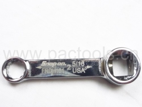
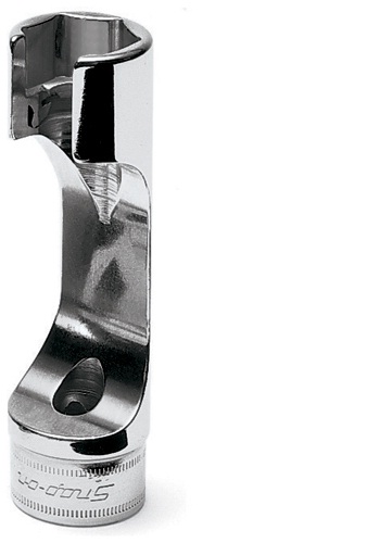
I do not know if either of these tools would work for this procedure, but they are interesting, and I have a similar tool to the second one, the box-end extended wrench. But my tool instead of a 12-point for a hex nut, has 12-bars-and-slots for special nuts shaped the same, wish I could find a picture, but the tool also works for hex nuts.
Certainly, perusing the Snap-On catalog can be instructive.
Certainly, perusing the Snap-On catalog can be instructive.
12-06-2012, 08:46 AM
#18
I Got It!
dcmodels:
Okay, I think I've got it! Those pictures of your tools are great. Now I need to get those tools. As they say, a picture is worth a thousand words! I understand what you are saying about the anti-seize. Cleaning the rust from bolt threads is always a good idea. If I were to do this job over, I would purchase new stabilizer link rods so that I could have new bolts to attach the new nuts onto. Always a good idea. I did not use anti-seize on the pinch bolts as they were new. I even had dealerships service departments tell me that they just re-used the old bolts and nuts when doing this job! As far as estimating torque by feel, I am going to pass on that as I don't do enough of that to feel competent at estimating torque by feel. I have heard people say that they can do it but I am not one of those people. The danger of over-torquing is a serious concern. I understand what you are saying. Thanks for clarifying. I can improve my next foray into the mechanical realm with this additional knowledge. Thanks for helping to clarify probably the most difficult part of this procedure!
12 51320-STK-A01 LINK, FR. STABILIZER 2 $19.31 $14.29
http://www.oemacuraparts.com/parts-c...hassis/knuckle
BTW, your tool pictures are only visible to members. I started using PhotoBucket by opening a free account with them and uploading my pictures to their server. Thanks to 737Jock for that! That way, the pictures are visible to anyone viewing the thread on the internet even those who are not members.
Okay, I think I've got it! Those pictures of your tools are great. Now I need to get those tools.
As they say, a picture is worth a thousand words! I understand what you are saying about the anti-seize. Cleaning the rust from bolt threads is always a good idea. If I were to do this job over, I would purchase new stabilizer link rods so that I could have new bolts to attach the new nuts onto. Always a good idea. I did not use anti-seize on the pinch bolts as they were new. I even had dealerships service departments tell me that they just re-used the old bolts and nuts when doing this job! As far as estimating torque by feel, I am going to pass on that as I don't do enough of that to feel competent at estimating torque by feel. I have heard people say that they can do it but I am not one of those people. The danger of over-torquing is a serious concern. I understand what you are saying. Thanks for clarifying. I can improve my next foray into the mechanical realm with this additional knowledge. Thanks for helping to clarify probably the most difficult part of this procedure!12 51320-STK-A01 LINK, FR. STABILIZER 2 $19.31 $14.29
http://www.oemacuraparts.com/parts-c...hassis/knuckle
BTW, your tool pictures are only visible to members. I started using PhotoBucket by opening a free account with them and uploading my pictures to their server. Thanks to 737Jock for that! That way, the pictures are visible to anyone viewing the thread on the internet even those who are not members.
Last edited by RangeRider49er; 12-06-2012 at 08:50 AM. Reason: Add comment on PhotoBucket.com
 12-06-2012, 04:28 PM
#20
haole kama'a-ina
If all engineers were as conscientious as dcmodels  our bridges wouldn't be falling down.
But in the absence of any good way to attach a torque wrench to the stab link, there are 2 other methods I can think of.
Scale method:
1. With a 9" wrench divide 58 ft/lb by 0.75 = 77 ft/lb
2. With a 12" wrench your ft/lbs don't need to be calculated ie. 58 ft/lb = 58 ft/lb @ 12".
3. With an 18" wrench divide 58 ft/lb by 1.5 = 39 ft/lb
4. Position a bathroom scale so you are putting direct force on the scale when in position to wrench.
5. Take a baseline scale measurement (it should be your weight, or something steady on one knee).
6. Pull on the wrench in a motion directly toward the scale until you add the calculated pounds to the baseline.
Bathroom scale? Seriously? Am I joking about this? Well, not too much. It is valid. People use this and when done right, it works.
Turn-of-Nut method:
This has been in use since the 1950s and tests in building construction have shown that it is 10% more accurate than a torque wrench. Because it is based on bolt length/diameter ratio, it automatically accounts for increased torque with larger bolts.
1. Turn fastener down to snug metal contact.
2. Refer to the Turn-of-Nut scale for flat surface fasteners.
The RDX front stab link shaft is about 4 diameters, so something not too much over 1/4 turn should torque the nut.
About 8 years ago, using a properly sized torque wrench, I broke a water pump bolt on my son's DSM-turbo-4G63**. The little #@&% bolt faced the frame with 30mm clearance (even with the engine lowered) and we lost a full day figuring out how to drill it out.
Since then, I have used Turn-of-Nut on all fasteners with a shaft diameter less than 12mm.
With all due apologies to dcmodels : I mostly use the torque wrench on wheel lugs and engine mounts, etc.
**Can we have a moment of silence please for the Mitsu 4G63
our bridges wouldn't be falling down.But in the absence of any good way to attach a torque wrench to the stab link, there are 2 other methods I can think of.
Scale method:
1. With a 9" wrench divide 58 ft/lb by 0.75 = 77 ft/lb
2. With a 12" wrench your ft/lbs don't need to be calculated ie. 58 ft/lb = 58 ft/lb @ 12".
3. With an 18" wrench divide 58 ft/lb by 1.5 = 39 ft/lb
4. Position a bathroom scale so you are putting direct force on the scale when in position to wrench.
5. Take a baseline scale measurement (it should be your weight, or something steady on one knee).
6. Pull on the wrench in a motion directly toward the scale until you add the calculated pounds to the baseline.
Bathroom scale? Seriously? Am I joking about this? Well, not too much.
It is valid. People use this and when done right, it works.Turn-of-Nut method:
This has been in use since the 1950s and tests in building construction have shown that it is 10% more accurate than a torque wrench. Because it is based on bolt length/diameter ratio, it automatically accounts for increased torque with larger bolts.
1. Turn fastener down to snug metal contact.
2. Refer to the Turn-of-Nut scale for flat surface fasteners.
A. Bolt length up to 4 bolt diameters = 1/3 turn
B. Bolt length between 4 and 8 bolt diameters = 1/2 turn
C. Bolt length longer than 8 bolt diameters = 2/3 turn
B. Bolt length between 4 and 8 bolt diameters = 1/2 turn
C. Bolt length longer than 8 bolt diameters = 2/3 turn
The RDX front stab link shaft is about 4 diameters, so something not too much over 1/4 turn should torque the nut.
About 8 years ago, using a properly sized torque wrench, I broke a water pump bolt on my son's DSM-turbo-4G63**. The little #@&% bolt faced the frame with 30mm clearance (even with the engine lowered) and we lost a full day figuring out how to drill it out.
Since then, I have used Turn-of-Nut on all fasteners with a shaft diameter less than 12mm.
With all due apologies to dcmodels
: I mostly use the torque wrench on wheel lugs and engine mounts, etc.**Can we have a moment of silence please for the Mitsu 4G63
Last edited by 737 Jock; 12-06-2012 at 04:36 PM.
12-06-2012, 06:22 PM
#22
Cool!
737 Jock, wow that's cool! I am leaning in favor of the TON method. I would probably get grease on the bathroom scale and my wife would get mad. That is something I never would have thought of but it sounds like a great idea for those of us who like to see a number reading for torque! Either way sounds good. Great solutions! Thanks to dcmodels and 737 Jock for the helpful and insightful additions to this thread. I think it is complete now. But don't let that stop anyone from further comments, pictures and suggestions as I always learn from the experience of others.
12-06-2012, 06:34 PM
#23

 01-08-2018, 05:59 PM
#25
Instructor

Join Date: Feb 2008
Age: 74
Posts: 147
Likes: 0
Received 0 Likes
on
0 Posts
Has anyone found replacement shock and strut cartridges (and probably spring as you'll read on) of the 07 RDX. Ours is my wife's car, and the ride has always been great for the driver, but the back seat is another thing. But now the car has 120k miles and I can tell that at least the front struts need replacement. I only want to go into the car one time, even if I'm paying my really great Honda/Acura independent garage to do the work. I'm a little uncomfortable buying the Eibach springs that only appear to be sold by heelandtoe if they aren't part of a completely engineered shock and strut package.
In absence of that, I'll just replace everything with Acura OEM parts.
In absence of that, I'll just replace everything with Acura OEM parts.
03-24-2019, 10:58 AM
#26

Just wanted to bump this to say thanks to RangeRider and everyone who contributed to the thread. I replaced the struts on my 08 RDX yesterday and the help here was invaluable. Also did the rear shocks, rear stabilizer links, and diff fluid so it was a long day. If anyone's in the market for a ratcheting wrench set, Lowe's has one for $50 that worked pretty well for me on this project. I also used the go-thru socket set mentioned earlier in this thread.
03-25-2019, 01:16 AM
#27

I'll be doing the same in a couple weeks! New strut assemblies, rear shocks, end links at all 4 corners, front and rear stabilizer bushings, and finally a set of rear pads because my original pads are finally done after 155k miles (on 3rd set of front pads).
Gonna be a fun weekend, but it'll be nice to have a smoother, quieter ride again. The original strut mounts have gotten pretty ugly over the last year.
Gonna be a fun weekend, but it'll be nice to have a smoother, quieter ride again. The original strut mounts have gotten pretty ugly over the last year.
03-25-2019, 07:34 AM
#28
I'll be doing the same in a couple weeks! New strut assemblies, rear shocks, end links at all 4 corners, front and rear stabilizer bushings, and finally a set of rear pads because my original pads are finally done after 155k miles (on 3rd set of front pads).
Gonna be a fun weekend, but it'll be nice to have a smoother, quieter ride again. The original strut mounts have gotten pretty ugly over the last year.
Gonna be a fun weekend, but it'll be nice to have a smoother, quieter ride again. The original strut mounts have gotten pretty ugly over the last year.
Came back to add a random tip - I used small bungie cords to keep the brake line and wheel sensor wires out of the way. I was nervous about the strut coming down on them. The suggestion up above to tilt the bottom of the strut assembly toward the front of the car on removal is also spot-on. On the first one I was surprised by the weight of the strut and it tipped toward the back and that became a bit of an issue when it got wedged in there funny. It took me a few minutes of wrestling to get the strut back up and out the proper way.
04-01-2019, 05:18 PM
#29
Completed the job this weekend. Took about 4 hours to do rear pads, rear shocks, front struts, all 4 end links and front/rear sway bar bushings. Looking at the old parts, the end links and bushings probably weren't needed, but quick and cheap to do while in there. The front strut dust boots had practically fallen apart, and the rear shocks compressed almost twice as fast as the new ones under equal weight. Safe to say their time was done.
To anyone doing this - make sure you get a pair of the special zip-ties that hold the wiring harness to the strut! They're a buck each at the dealership and will save you a ton of time.
Car rides stiffer, quieter, and corners flatter now. Great improvement, and I can't wait to compound that with some new tires soon. My current ones have maybe 5k miles left, so considering I'm already riding on old, stiff rubber, the difference I'm getting with the new suspension is fantastic.
04-02-2019, 03:20 PM
#30
Advanced

Completed the job this weekend. Took about 4 hours to do rear pads, rear shocks, front struts, all 4 end links and front/rear sway bar bushings. Looking at the old parts, the end links and bushings probably weren't needed, but quick and cheap to do while in there. The front strut dust boots had practically fallen apart, and the rear shocks compressed almost twice as fast as the new ones under equal weight. Safe to say their time was done.
To anyone doing this - make sure you get a pair of the special zip-ties that hold the wiring harness to the strut! They're a buck each at the dealership and will save you a ton of time.
Car rides stiffer, quieter, and corners flatter now. Great improvement, and I can't wait to compound that with some new tires soon. My current ones have maybe 5k miles left, so considering I'm already riding on old, stiff rubber, the difference I'm getting with the new suspension is fantastic.
To anyone doing this - make sure you get a pair of the special zip-ties that hold the wiring harness to the strut! They're a buck each at the dealership and will save you a ton of time.
Car rides stiffer, quieter, and corners flatter now. Great improvement, and I can't wait to compound that with some new tires soon. My current ones have maybe 5k miles left, so considering I'm already riding on old, stiff rubber, the difference I'm getting with the new suspension is fantastic.
04-03-2019, 12:43 PM
#31
It's part# 91507-STK-A01. If you're looking under the fender with the wheel off, you'll see a wire coming down from the engine compartment that has a mounting point just off the body, another on the strut (both are metal brackets with a rubber mount that holds the wire and slides into the bracket), and finally a little zip-tie that holds it tight against the strut. Follow that wire further and you'll see it plugs into the hub. I believe it's the speed sensor and also the receiver for the TPMS. All of this runs along the rear side of the strut, while the brake line is on the front side. You won't see it on the strut diagram, but check out the knuckle diagram and you'll see the wire along with the mounts.
Using one of the OP's pics, it's the zip-tie here. But the OEM version will most likely have been cut very close to the base, and covered in grime, so it may not even resemble a zip-tie anymore. I just sawed through the base to remove it from the strut, and used a small pair of scissors to carefully remove the rest of it from the wire.
Using one of the OP's pics, it's the zip-tie here. But the OEM version will most likely have been cut very close to the base, and covered in grime, so it may not even resemble a zip-tie anymore. I just sawed through the base to remove it from the strut, and used a small pair of scissors to carefully remove the rest of it from the wire.
04-05-2019, 09:36 PM
#32
CSmoney28
Yeah, the rdx struts went on me so I did BC coil-overs. They were making so much noise at the end of their life. The end links snapped on me had to replace them.
I can�t believe your rear brakes lasted that long...
I can�t believe your rear brakes lasted that long...
07-01-2020, 07:52 PM
#34
Instructor
I tried strut replacement today . No go. Sway bar link bolts were so rusted on, the bolts will have to be cut off. I bought new links. So replacing sway bar links, struts, and drive axles.
BTW, the Allen bolt hole is 6mm, not 5, at least for a 2012 Rdx.
BTW, the Allen bolt hole is 6mm, not 5, at least for a 2012 Rdx.

Thread
Thread Starter
Forum
Replies
Last Post