When you click on links to various merchants on this site and make a purchase, this can result in this site earning a commission. Affiliate programs and affiliations include, but are not limited to, the eBay Partner Network.
Hey guys, I'm looking to see if anyone has any experience with this plug and play LED flasher relay from Diode Dynamics. I could not find any threads on Acurazine related to this product. I know some people modify the stock relay with a different resistor or just use load resistors when switching to LED bulbs. This one claims to plug right in and fix the hyperflash issue. It wasn't cheap and comes with a 3 year warranty. I haven't installed it yet, but I'm curious if anyone else has and what their experience was.
Here is a link to the product:
https://www.diodedynamics.com/led-flasher-for-2004-2008-acura-tl.html
Dude - test it out and report back, I'm interested to know if it works!
I definitely plan to, it's just very cold here right now and I don't want to snap any plastic. Going to try to get it installed within the next few days and I will report back.
I definitely plan to, it's just very cold here right now and I don't want to snap any plastic. Going to try to get it installed within the next few days and I will report back.
I had considered this flasher relay but couldn't justify paying $60 when I could go to a local junkyard, find an OEM flasher relay from a TL(or a Honda Odyssey, Element, Ridgeline or Accord, same part) for $3 and do the DIY resistor mod. The mod worked awesome and the VLEDs I put in makes it look updated and modern, relatively cheap and easy mod. I've got pictures I took while doing the mod and an after video of the LEDs in action.
Sorry, I haven't tried it yet. I've had to work a lot of overtime this past week and the weather has been awful. I might try tomorrow.
I just bought some new VLEDs switchbacks and one of them just stopped working last night so I'm having to deal with that issue. I'm also having to dig through the previous owners wiring job for the load resistors so that I have no exposed wiring when I remove them. Not the best time of the year here to tackle this task.
I had considered this flasher relay but couldn't justify paying $60 when I could go to a local junkyard, find an OEM flasher relay from a TL(or a Honda Odyssey, Element, Ridgeline or Accord, same part) for $3 and do the DIY resistor mod. The mod worked awesome and the VLEDs I put in makes it look updated and modern, relatively cheap and easy mod. I've got pictures I took while doing the mod and an after video of the LEDs in action.
That's true. I didn't read about that mod until after I purchased this flasher relay. I hopped on it quick because they had a Cyber Monday sale.
I actually just walked out from dinner and now both my VLEDs switchbacks won't work at all. Very strange, not sure what would cause this to happen. I had other LED switchbacks in there before with the same load resistors and zero issues.
Perhaps you can help me out. Does the OEM flasher relay just pull straight out or are there tabs that I need to depress for it to be removed? I don't want to break anything and it's hard to see in the area . I read that it's in there pretty tight, I assumed pliers with a 90� bend would be the tool of choice?
Just got it out, it did have a tab on each side. I had push out on both tabs simultaneously as I pulled and wiggled it out. Not too bad, just in a very tight area.
Just wanted to make note of that in case anyone reads this in the future so they don't break anything. I'm not sure if it would have come out just from wiggling and pulling it, seems like you have to push the tabs out.
It was definitely in there tight and made me feel like I was going to break something! I did pull it out by hand though, no pliers. It helps to use a small flathead screwdriver to push the tabs out.
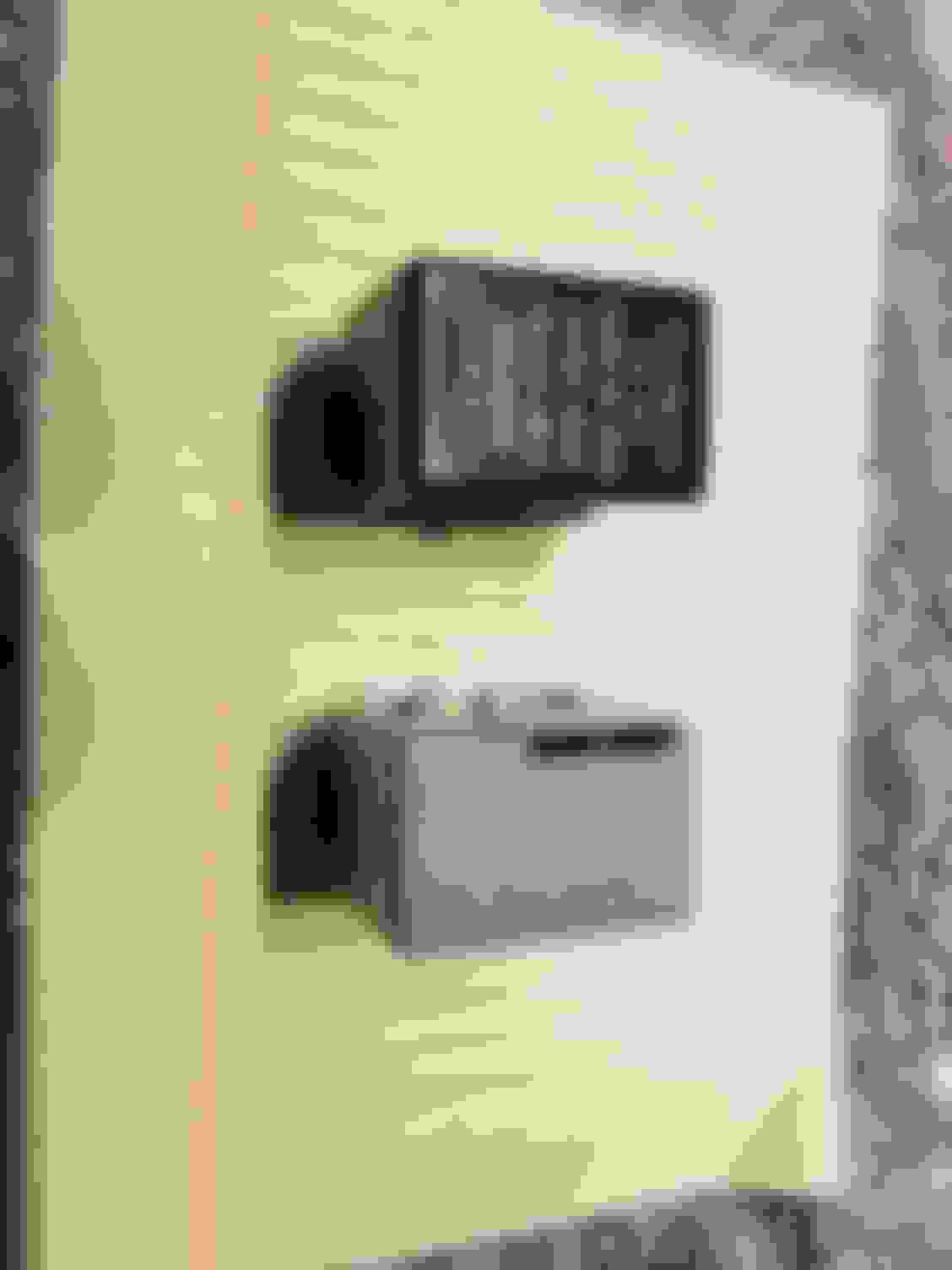
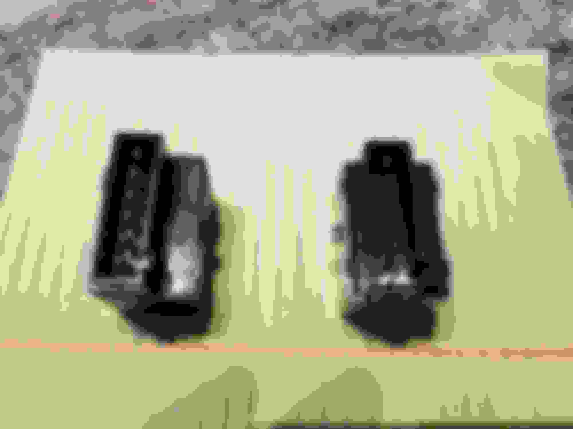
Some pics for reference. Comparing OEM flasher relay vs the Diode Dynamics flasher relay. The small triangular pieces on the sides are what lock into the tabs if anyone was wondering what I meant.
Not highest quality pics, but they look identical and the wattage numbers are the same on each. I will install the LED flasher relay and report back on the results tomorrow.
Update: After digging through the previous owners wiring job I removed the load resistors. I installed the Diode Dynamics (Intermotor) LED flasher relay along with my old set of Lucenta LED switchbacks and tested the blinkers on both sides and the hazards. They all work at normal speed, no hyperflash!
So I am currently running Lucenta LED switchbacks in the front and regular OEM incandescent bulbs in the rear. I plan on changing out the rears with VLEDs soon, especially now that I don't have to wire in load resistors.
I still am clueless as to why my VLEDs switchbacks both failed, yet the Lucentas are working fine. With that being said, the VLEDs were definitely brighter and looked like higher quality LEDs. I'm sure VLEDs customer service will take care of me Monday.
This is a very straightforward install, hardest part is getting the OEM flasher relay out. I agree modding the OEM flasher relay is much cheaper, but this is another option for people. I will report back to this thread periodically to see if this relay stands the test of time. It carries a 3-year replacement warranty from Diode Dynamics.
If anyone has any questions please don't hesitate to ask me. I would also suggest disconnecting the negative terminal on your battery as a precaution. I could be wrong, but I always disconnect it while working with electrical components. If any of this info seems incorrect somebody please correct me as I do not claim to be a pro.
One month update. The flasher relay is working perfect. The issues with the VLED bulbs were on their end, it had to do with the circuit board I believe they said. Either way, nothing to do with the flasher relay. Replaced my OEM rear blinker bulbs with VLEDs bulbs, no issues at all. Still blinks and works as it should.
I'm glad to see that it is working for you and that there is an alternative for those who don't want to modify their OEM turn signal relay.
However, in 2015, I opened up my OEM turn signal relay and swapped the resistors with my soldering iron for just a few pennies. It took no more than 30 min from start to finish.
I know I soldered two resistors to the relay, so I want to say they were both 0.12 Ohm resisters. I cannot comment on whether or not two 0.12s or one 0.24 will make a difference. I'm sure Peter knows though lol.
It all depends on how much current new bulbs draw.
Taken from the IC datasheet:
That means that with stock shunt resistor, relay will fault out (hyperflash) if it sees under 2.5A at 12V. One standard turn signal bulb will draw around 2A, two bulbs will draw around 4A. Only when two bulbs are working current is over the 2.5A, and only then IC is assuming all is fine and continues flashing normally.
If you replace the shunt (0.02 Ohm) with 0.12 Ohm resistor, relay will fault out if it sees under 0.42A. With 0.24 Ohm resistor it will fault out if it sees under 0.21A.
It seems like using higher value resistor is a good idea, as it will push minimum current lower and lower. The problem is that all of the power going to the turn signals goes through this resistor. Higher value means more power, more losses, more heat and higher voltage drop across the resistor. And we don't want that. Too much heat and things will go wrong.
Second best idea would be to measure how much current your new bulbs will draw, and select resistor based on that. You could even keep the fault detection in case one bulb would fail.
Thirds best is to use "universal" value of 0.12 Ohm. It works, requires least amount of work, and is already in use by many (including me).
In worst case (stock bulbs, hazards on), 0.12 Ohm resistor would see 8A going through it, making it work at ~6.5W @ 50% duty cycle. That's too much for 1W resistor.
Hi Peter,
I replaced the stock shunt resistor with a 0.24 ohm resistor and had the rear turn signals running Philips Ultinon LED 7440 bulbs while the front ones were still the OEM incandescent bulbs. The setup worked for a minute and then it started buzzing before it went fully dead. When I removed the relay I could smell something burning and sure enough the resistor had blackened. I am trying to see what I did wrong here - perhaps I used a resistor with low wattage? perhaps the bulbs use more current so I need a lower resistance - the bulbs don't list the current they need.
Below are the resistor details:
Power: 1 watt
Resistance: 0R24
1% metal film resistor.
Now I am running a Duralast relay that I got from Autozone for $17
Automotive bulbs usually list what wattage are they, assuming powered from ~12V source. Standard 7443 bulb as turn signal runs at ~25W, so at 12V it's 2.1A going to the bulb.
Since all that current also needs to go through that resistor, 2.1A going through 0.24 resistor will make it work at around 1W not counting the rear turn signals. If your soldering wasn't perfect then that also introduced additional resistance = additional heat. That's cutting it close.
Either do it "the right way", switch to all leds before modifying relay, or use two of 0.24 1W resistors in parallel to reduce resistance and distribute load.
Thanks Peter. I thought the box will have the wattage but it doesn't. I searched on the internet but haven't found anything yet.
So if I use two 0.24 ohm resistors in parallel, the resultant resistance will be 0.12 ohms. Which at 2.1A will equal 0.53 watts. 53% capacity of the resistor. Will this be cutting it too close? If I have hazards on with 2 LEDs in the rear and 2 incandescent bulbs in the front, the total current will be at least 2.1A + 2.1A - 4.2A without counting LEDs, the resulting power would be more than 1 watt. So it won't work in that scenario correct?
If I replace all 4 bulbs with LEDs and use one 0.24 ohm resistor, I think I will be fine as long as each bulb draws less than 0.36A?
0.36A * 4 = 1.44 A, P= 0.5 Watt (50% of 1 watt resistor)
Bear with me, I haven't done such calculations since school.
Technically resistor should handle more than 1W of power since it doesn't run constantly, but being in the small closed box that doesn't provide good insulation doesn't help.
By using two resistors in parallel, your equivalent resistor is 0.12 ohm and 2W. If you can space them so they don't touch it will help with cooling as well.
I've been running 0.12 1W resistor for years now without any problems, but I don't know how much current my setup draws (all LEDs).
Time flies, the flasher relay still works perfectly for anyone reading this thread these days. I'm still running VLEDS switchbacks in front and VLEDS blinkers in the rear
Thank you for the insight. I have a 2007 TLS, my 2008 TL has load resistors that I installed like 7 years ago ND ever been elated with thar set up, SO THANK YOU very much for the insight with relay part!!!
Just shy of 4 years and the flasher relay is still working perfectly. Running Diode Dynamics front switchback LEDs and VLEDS rear turn signal LEDs currently.
Just shy of 4 years and the flasher relay is still working perfectly. Running Diode Dynamics front switchback LEDs and VLEDS rear turn signal LEDs currently.
hey just a quick Q, Does that flashers turn signal click sound any different? I know the oem flasher sounds like any 2000s car, but I was wondering if this one has a slightly more modern sound to it like the newer cars do.
hey just a quick Q, Does that flashers turn signal click sound any different? I know the oem flasher sounds like any 2000s car, but I was wondering if this one has a slightly more modern sound to it like the newer cars do.
 12-07-2019, 03:37 PM