When you click on links to various merchants on this site and make a purchase, this can result in this site earning a commission. Affiliate programs and affiliations include, but are not limited to, the eBay Partner Network.
DIY: How to Add Blind Spot Information (BLIS) to Your TL for under $100
Hello! I will show you how to add a Blind Spot Information System (BLIS) to your TL. If you've installed the rear parking sensors before, this will be easy.
PURCHASING MATERIALS:
I purchased the following materials from Amazon:
1. BLIS LED Warning Light Indicators. Comes with two indicators, one for the left and one for the right. Cost is $32.99.
OTHER NEEDED MATERIALS:
-10mm socket
-12mm socket
-7mm drill bit (for the BLIS LED indicators)
-Trim panel remover
-Philips head screwdriver
-Wire cutter/trimmer
-Switch (if you want to turn the BLIS sensors on and off)
-Electrical tape
-Zip ties
-Add a fuse system (I had one available)
DISCLAIMER: What you do to your car is your responsibility. Below are just suggestions as to what can be done.
General steps are to do the following (detailed steps are in subsequent posts):
1. Paint the sensors the color of your car. Wait at least ten minutes before your final color coat and your clear coat.
2. Remove the rear bumper.
3. Mark where you want to drill for the "parking sensor" (we are using an ultrasonic parking sensor as the sensor and trigger for the LED indicator). Drill a 22mm hole on either side of the bumper, facing out, as high as you are comfortable drilling. Mark a template and then reverse the template on the other side. Use the ends and lines of the bumper as your guide. Pay attention to the orientation of the sensor.
4. Clean up the burrs and rough edges of the holes you just drilled.
5. Install the left and right ultrasonic sensors. See above picture for what I did to my car.
6. Route the wires through the hole in the trunk and the rubber grommet.
7. Remove the left trunk carpet and trim.
8. Remove the rear seat and rear seat bottom.
9. Connect the ultrasonic sensors (left and right) to left and right BLIS control boxes. Only connect one sensor to each control box. It doesn't matter which of the four slots you connect the sensors to. I connected mine to the first slot on each control box. Make sure you mark which sensor is which. I marked mine with a white dot to indicate the left BLIS Control box.
10. Zip tie the left and right BLIS control boxes together.
11. Connect the +12V and ground (red and black wires) cable to the "Power" slot of each of the left and right BLIS control boxes. Solder the red wires together and then solder the black wires together.
12. Solder 20 ft of the red and black 16 gauge wire to the red/black power wire from the BLIS Control boxes.
13. Route the wire on the left side under the plastic trim pieces.
14. Solder one end of the red wire to one side of a simple on/off switch. I used a two prong rocker switch. Solder 6 inches of red wire to the other prong of the switch.
15. Connect the red +12V wire to the ignition wire from the add-a-fuse.
16. Connect the black ground from the BLIS Control boxes to a solid ground on the car.
17. Remove the left and right front door trim panel. There are three Philips head screws to remove: two under the black trim piece by the interior door handle and one in the arm rest on each door. Remove the door stopper using a Philips head
18. Remove the side view mirror black trim piece on each side of the car.
19. Drill a hole for the BLIS LED Indicator lights on each of the left and right side mirror trim pieces.
20. Install the BLIS LED Indicator lights in the hole you just drilled.
21. Route the wires through the door and through the rubber grommets on both the door and the car.
22. Clip the plastic connector from each side of the BLIS LED Indicator lights.
23. Solder red and black extension wires to the clipped off wires. There will be two red wires and two black wires (one red and black for the left BLIS Indicator LED and one red and one black for the right Indicator LED)
24. Route the LED Indicator extension wires under the left and right trim pieces and to the back. I routed mine to under the rear seat and then zip tied them together on the driver's side. I routed the wires to the left and right BLIS Control boxes in the rear.
25. Solder a 150ohm resistor in series to each black wire on each of the BLIS Indicator lights. The output trigger puts out ~6.37V, so I needed a voltage dropping resistor for EACH BLIS LED Indicator.
26. Connect the left LED Indicator light wires (red and black with the resistor) to the left BLIS Control Box. You will have to solder the wires to the connection labeled with a horn symbol. Pay attention to polarity. If the LED does not light up, switch the wires around.
27. Connect the right LED Indicator light wires (red and black with the resistor) to the right BLIS Control Box. You will have to solder the wires to the connection labeled with a horn symbol. Pay attention to polarity. If the LED does not light up, switch the wires around.
28. Turn on the car and test the system. Once you walk by the sensor, the light on that side of the car will light up. If it does not, check for polarity on the control box of the led.
29. Install the plastic trim pieces in the car.
30. Reinstall the rear bumper. Route the wires and zip tie them to existing wire bundles.
31. Reinstall the left and right front door trim panel and side view mirror trim pieces. Zip tie wires to existing wire bundles.
32. Reinstall the trunk trim pieces.
33. Reinstall the rear seat.
Interesting write up! I'm very curious for pics and a video too if you could? Does the thickness of the paint on the sensors affect the performance I wonder?
I didn't have all the components yet. I will start painting tonight. I have to find time this weekend to take off the rear bumper and see if there is clearance behind where I want to stick the sensor. The two outer sensors on the rear parking sensor might work as well (they're already installed).
Phase 1 complete (painting the sensors and installing them in the rear bumper).
I started by painting the BLIS sensors Carbon Bronze Pearl. (Picture below)
I painted two coats of CBP and two coats of clear. I waited ten minutes between each coat of paint as per the instructions.
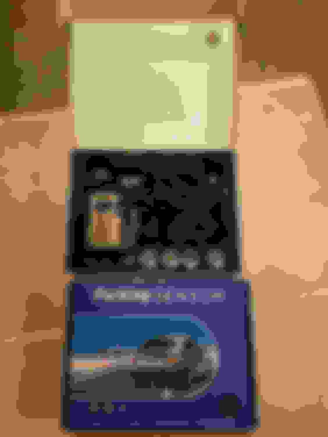
Here is what the rear parking sensor kit looks like (the gray color is actually very close to the color of the CBP at a distance):
I modified the control box so that I could get a light output instead of a beeping sound. That would get annoying quick. Of course, if you REALLY wanted to get fancy you could hook the beeper sound to each blinker. The picture below shows the control box and where I added the white connection to the control box. In other words, it was blank before. I took off the top of the control box, and soldered a new white electrical connection to the blank spot so that I could add a resistor and LED to that electrical connection. I did this for each of the two control boxes as each control box will control each of the left and right LED indicators by the side mirrors.
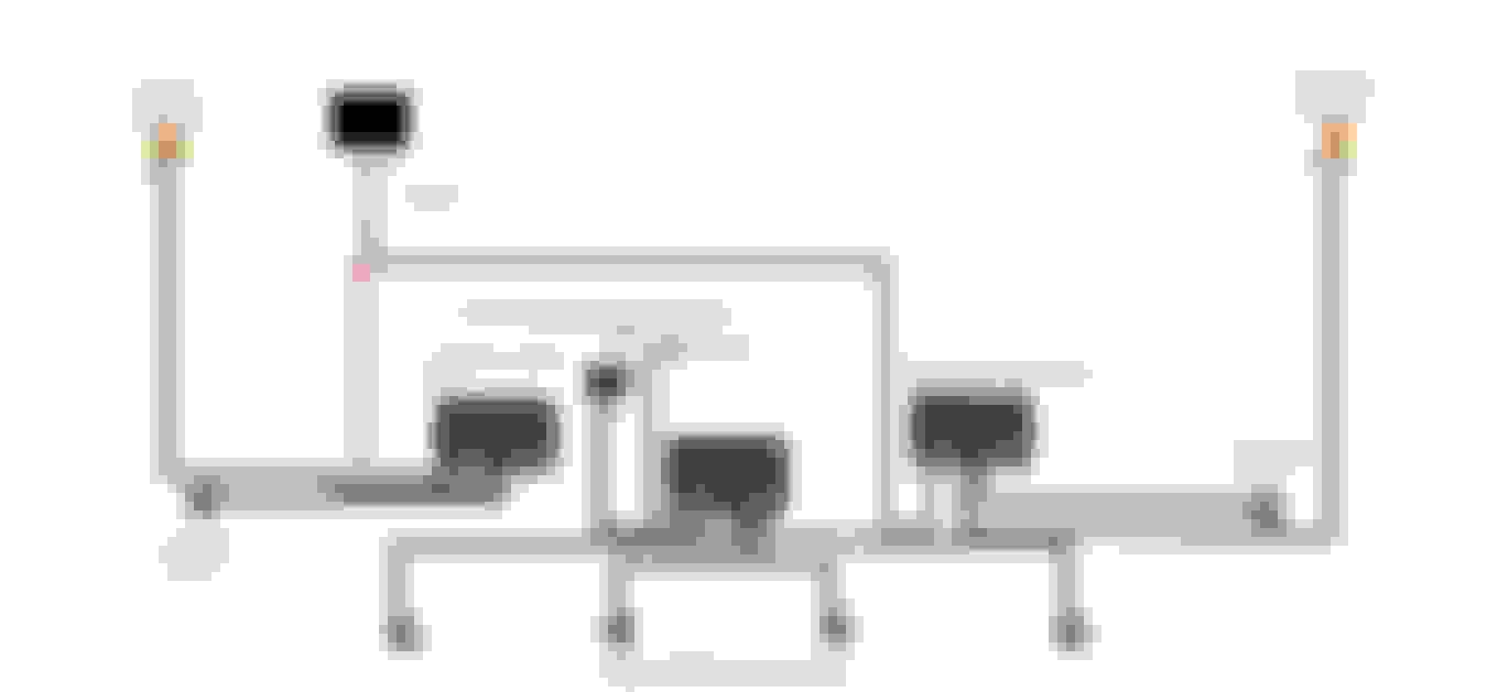
I then tested and measured the optimum placement of the sensor. The sensors detect objects up to 2.6 ft away, which is where by fingers are in the below pictures. It's quite close. The actual BLIS system detects objects using 24GHz microwave radar from a farther distance, but the cheapest system I could find was five times the cost of the components I paid for.
I did not want the sensors to pick up curbs or bushes, so I installed it higher on the rear bumper. Below are the location measurements of the little tiny mark I made.
Left sensor installed (but not hooked up yet).
I used a piece of paper to copy and transfer exactly where the sensor is to use that as a template for the opposite side.
Left sensor installed. The lower sensors are for the rear parking system sensors in the stock OEM locations.
The removal of the sides of the rear bumper was a pain in the ass. I ultimately had to do it for each side because I could not find a way to run wires into the trunk without doing this.
Next up: Phase two, where I hook up the control boxes and run the power and LED indicator light wires to the front.
So I took off the driver's side door panel. You first have to take off the plastic cover piece behind the interior pull handle. Then remove the two screws there, remove the screw under the black pull handle, and then remove the bumper screw on the rear of the door. Then the interior insert will pull up and off.
I drilled a .8" diameter hole in the side view mirror plastic trim and then used black goop to glue the left BLIS LED indicator to the hole. I then routed the wires inside the door and through the rubber grommets. Tomorrow I will wire up the LEDs.
If you buy those LEDs please be careful because the max voltage these LEDs is 2V. Because the BLIS control box puts out about 3.4V, you will need a voltage-dropping resistor of about 28 ohms, assuming the LED is 50mA of current.
So I discovered something interesting. The two different BLIS control boxes are hooked up to the same circuit. However, apparently so are the BLIS LED indicators, somehow, even though they're coming from different control boxes. It does work however, and I just need to figure out why both indicators are lighting up even though only one sensor is detecting an object.
So I discovered something interesting. The two different BLIS control boxes are hooked up to the same circuit. However, apparently so are the BLIS LED indicators, somehow, even though they're coming from different control boxes. It does work however, and I just need to figure out why both indicators are lighting up even though only one sensor is detecting an object.
seperate the grounds and power sources, I'd use a relay+ switch rather than switch only, use a diode to help identify the issue! Also where did you buy paint from? Looked online at a few places and it's STUPID expensive! Are you using 3 boxes for rear parking sensors also or just 2 provides that or no parking sensor usage?
From a logical standpoint, I should not have to separate the sources because the boxes each control one output each. How they are crossed, I have no idea. However, I will do that to see if it works.
I used two separate control boxes to get two independent outputs, one from each control box. Had the control boxes allowed multiple outputs, I would only need one box.
Great job so far, looking forward to remaining details!
Originally Posted by gatrhumpy
From a logical standpoint, I should not have to separate the sources because the boxes each control one output each. How they are crossed, I have no idea. However, I will do that to see if it works.
I used two separate control boxes to get two independent outputs, one from each control box. Had the control boxes allowed multiple outputs, I would only need one box.
Maybe voltage test each of control boxes would give some clue, voltage or direction?
 06-09-2019, 08:01 PM