When you click on links to various merchants on this site and make a purchase, this can result in this site earning a commission. Affiliate programs and affiliations include, but are not limited to, the eBay Partner Network.
*The 2007-08 base model steering wheel wiring harness is different than the 2007-08 Type-S steering wheel wiring harness*
The original picture in section D shows the pin location of the wires that come FROM the Type-S steering wheel wiring harness and where they exit into the vehicle at the back of the clock spring. The pins flip/flop a bit (within the clock spring) and it took some time with a multimeter to figure this out. You'll notice that the white clip attaches upside down inside the steering wheel to the front of the clock spring, while the dash white clip attaches right-side-up at the rear of the clock spring. Here is another picture that hopefully helps clarify:
Last edited by wusty23jd; Apr 28, 2022 at 12:14 AM.
Here is the pin-out layout for those seeking to do this swap.
I searched but didn't find this info anywhere therefore I went ahead and research it so others can benefit as well.
LEGEND:
ORANGE==>CUSTOM WIRING NEEDED
GREEN==> CORRECT PINOUT CONFIRMED TO DO COVERSION
RED==> FOR THE TYPE-S PADDLE SWITCHES--DON'T NEED IT SINCE I DON'T HAVE A/T TRANSMISSION
GRAY==>PINS NOT IN USE
When not using the 07/08 clocks spring, for the select/reset/information buttons are you just running a cable from the steering wheel harness directly to the cluster? Wouldn�t that cause a problem with steering?or are you opening the clock spring and going through there? Please help
If anyone wants to add a 2007-08 Type-S steering wheel with working paddle shifters to a 2004-06 automatic base model, my retro fit is finally complete. I wanted to simplify the confusion, so please refer to THIS post for final information Please note that you WILL need a 2007-08 clock spring for this to work.
I. Custom Wiring Harness
Instead of re-pinning the wires inside my car, I made a custom wiring harness adapter, which is plug and play and will allow me to resort back to stock if I chose to in the future. Making the custom wiring harness consisted of the following:
A. I found a male end pigtail from a 2007-08 Type-S dash harness (This is the white plug that connects to the back of the clock spring)
B. I found a female end from a 2004-06 Base clock spring. I opened up a clock spring at my local junk yard and dremeled it down in size later so it would fit inside the steering column. The picture below shows the part I'm referring to. The four wires showing are from the airbag wiring harness.
C. Once I had both pieces, I disassembled the clock spring female connector and soldered red wires to the pins.
D. After a lot of research, I developed two conversion charts, which show how the pins need to be relocated.
E. After figuring out the wiring, I created this bulky wiring harness.
F. After finding out that the bulky wiring harness would not fit inside my steering column with enough room for the covers to close, I dremeled off the airbag wire pins and also the boxy corners to make a slimmer harness.
II. Wire Tapping
A. I used T-taps and spade connectors to tap into the wires for the paddle shifters. Please note I had a lot of trouble at first after thinking I was supposed to tap into the ORN wire (You'll see an empty/unused T-tap in my picture below.). I later found out that I needed to tap into the BLU/YEL wire and the BLU/WHT wire.
B. I also used T-taps and spade connectors to tap into the three wires for the Information Up, Information Down, and Select/Reset buttons. I don't have a good quality picture of this, but you'll see the necessary wire taps within my wiring harness to the right just below the gauge cluster.
III. Adding LEDs
A. While I had my steering wheel torn apart, I decided to finish my LAST LED interior conversion. When soldering the LEDs, I completed several test runs, making sure to aim the LEDs just right, so that there weren't any hot or cold spots on the button face.
B. I also found that the lights were not shining nearly as bright as my other LEDs. I believe Acura used stronger resistors within the steering wheel to help eliminate bright lights shining directly into the driver's face. However, they were still a bit too dull for my liking, so I used an X-Acto knife and cut out the thin rubber film covering the holes for where the LEDs shine through.
ive tried to understand how this harness type thing you have going on works, but i just cant manage to figure it out, is there a way you could help me out on this? ive made an account just to ask lol. I have all the parts ready just need to figure out how to the wiring works
You're right about there being a lot of info on how to figure this out but maybe im not comprehending too well. I followed your steps up to 1 A-C. I'm currently at D trying to figure out what colored wires get attached to what red wires that was soldered onto the Female end off the 04-06 base clock spring. that part is confusing me. i have exactly all the parts needed for this conversion.
So i guess the questions i have are:
1.) the harness you've created is a direct plug n play once its created correct? what colors go from the 22g red wires that i soldered onto the female plug and in which order?
2.) is there any relocating wires on any of the plugs that i need to do first? if so which ones are they? and what diagram should i be following?
i took the time to come up with a diagram on the male pigtail i have from the type s but i cant post it since im still new to the community. it looks exactly like the one in your picture. Mind you i do have an 04 and im missing only one wire on the main harness inside the car and its for a navi. Im sure i can bypass it, but I appreciate your time and any input you can put into helping me figure this out.
Okay, I will self-proclaim that it has been a while since I worked through this, so I had to revisit my work. I'm hoping that the below is correct.
Firstly, yes this is a plug-and-play feature. That was the sole purpose for creating this wiring harness (so that I didn't have to re-pin anything or solder inside my TL).
However, keep in mind that the goal of this conversion is to take a 2007-08 steering wheel and 2007-08 clock spring, (which each have 20 pins) and retro fit this to fit a 2004-06 TL, which has a white plug with only 16 pins coming from the dashboard.
Please note that the Type-S plugs do have a few blank pins, so you don't actually have 20 wires to work with. I'm just trying to clarify the differences.
Furthermore, there are 5 wires that need to be connected inside your TL to maintain gauge cluster buttons and to incorporate the paddle shifters. That's why you see 5 wires dangling within the below wiring harness. These are also highlighted separately in my conversion chart in DIAGRAM 1.
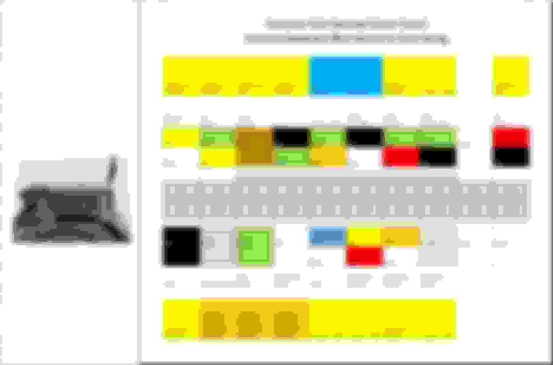
My recommendation would be to focus the DIAGRAM 1 first. Once you are able to understand the correct pin location, you'll see directions in the cells directly above or below. Below are a few examples:
"Resume Switch": Pin 1 (from DIAGRAM 1) needs to connect to the the GRN/BLK wire (from DIAGRAM 2). In this case, it ends up being pin location 9.
"HFL System": Pin 10 (from DIAGRAM 1) needs to connect to the ORN wire (from DIAGRAM 2). In this case, it ends up being pin location 16.
"Paddle Upshift": Pin 5 (from Diagram 1) needs to connect to the BLU/YEL wire (inside your shifter column).
Yellow: These pins need to be soldered to the corresponding wires referenced.
Blue: These two pins need to be wired to the two upshift/downshift wires in the gear shifter
Orange: These three pins need to be tapped into the wires within your gague cluster buttons
DIAGRAM 1
DIAGRAM 2
Last edited by wusty23jd; Sep 3, 2023 at 02:21 PM.
*Also, please keep in mind that the white plug that you see in my picture above is from a junk yard 2007-08 Type-S. I cut this out from a 2007-08 dashboard wiring harness (the plug that comes from behind the dash and plugs into the back of the clock spring). So what I'm saying is don't focus on the color of wires you see in thatpicture. Just focus on the color coding from the diagrams that I shared above and the directions I outlined for each pin.
your diagram 1 is actually my control harness that sits inside (behind the air bag) how does that correlate?
dude if im making this hard feel free to call me names, i just want to complete this project and your the only god given person whos actually completed this and gave direction.
BELOW ARE MY DIAGRAMS I MADE LASTNIGHT
the 6 grey tabs below the numbers is the push tab and thats the direction its facing in the steering wheel that will connect to the the front of the clock spring. this is similar to your diagram 1 but yours is maybe backwards? this is the main harness connector that plugs into the female end of the custom harness this is the diagram i had made lastnight of the type s pigtail which i cant find in this thread. on which ones connect.
i guess an easier question to ask is, do both front and back of the clock spring correspond? because that's what im understanding from what you're telling me from the diagrams?
Example.
First Picture
Okay, so this part was a bit confusing, but it requires some clarification. My DIAGRAM 1 and your picture are NOT the same. What I can tell you is do NOT focus on the pinout that you created/posted above (i.e. the male plug that sits inside the steering wheel). The reason I say this is because the pinout locations actually flip from the front of the clock spring to the rear of the clock spring. For example, the top row and bottom row flip-flop and also they flip left/right inside the clock spring. It makes it a bit confusing, but you can use a multimeter if you want to double check the front pins and back pins of the clock spring yourself. Trust me, focus on my DIAGRAM 1. This is the rear of the clock spring that you will plug your custom wiring harness into.
Second Picture
This looks correct and matches my diagram as well (besides the navigation wire).
Third Picture
So, I just needed a 20-pin white plug and this is exactly the plug that I used for my conversion as well. Do not focus on the colors of the wires from your pigtail. Just focus on what pin location the wire comes from.
For example, take Pin 16 (which I guess is a RED/BLU wire in this case) and match it up with Pin 16 from my Diagram 1. What does the conversion chart say? It says Pin 16 represents the "Illumination Negative' wire and you should connect it to Pin 3 from the 04-06 o
Another example, take Pin 5 (which I guess is a LT BLU wire in this case) and match it up with PIN 5 from my Diagram 1. What does the conversion chart say? It says Pin 5 represents the "Paddle Upshift" wire and you should connect it to the BLU/YEL wire in shifter column.
Thank you for making this more clear, and especially for the mark up on the chart. I just connected all but one wire which is 11 (blk) because i dont have a blue/wht on 04-base harness. Is this a concern? it says its a g501 and from short research, its a ground right?
Okay, so here's my progress. IM SO CLOSE. I went for it and tackled the soldering of the female connector to the male pigtail. Everything went well and its somewhat of a success, except a few things. most of the controls work on the steering wheel its self with an exemption of a few. The 5 wires that aren't soldered to anything. below are pictures and explanations of the issues im having. any input is appreciated. PS I can see why you made your harness as small as possible because its going to be a pain to fit it into the small space provided.
PIC 1 starting with the bottom, Pins 12, 13, and 14. (PIC 2) These are for the MID controls and i tapped them just as the diagram shows and there's no response at all. Pins 5, and 6 im having some trouble as well because pin 5 to blue/yelw (upshift) works no problem but downshift is where im having trouble (PIC 3) PIC 2
MID controls: Before hand i had those quick splices (blue) on the right for all connections and thought maybe that was the problem, so i switched those out with the T connects and still no response. Am I doing something wrong here? If i use orig button connections then it works no problem just not on the steering wheel controls. It is wired just like the diagram and i even went over some of the older comments above to see if i missed something but couldn't find anything.
PIC 3
PIN 5 connects to blue/yelw WORKS!
PIN 6 connects to white/blue but the problem is i don't have a white/blue wire. I read this thread and it showed that there needs to be three wires that are tapped but confused on it because its only for 07-08 base models. any advice? I tried only tapping into the black negative like the picture provided but nothing worked for downshift.
PIC 4 this shows the connection/ taps for the paddle shifters. not really important i just posted it just incase it needed to looked at
Let's start with your paddle shifters. Fortunately, my TL is still torn apart (for other reasons), so I took some pictures.
I can confirm that I only needed to tap into two wires to get the paddle shifters to work (One for upshift and one for downshift). The harness itself should already be grounded. In my 2005 base, I have a BLU/WHT and BLU/YEL wires.
IGNORE THE ORANGE WIRE TAP. THIS WAS LATER DETERMINED TO BE N/A FOR MY APPLICATION.
If you don't have the BLU/WHT wire present, my recommendation would be to tap into the wire that comes from the same pin location. For me, if you're sitting in the driver's seat looking down, it's the bottom right pin. As you'll see below, this is where my BLU/WHT wire is present. Try this and see if it works.
If you can locate a wiring diagram for this connector, I think that would be best. Otherwise, proceed like I recommended above.
NICE IT WORKED! Were getting closer to a finished steering wheel and i hope this helps out someone like myself who's trying to do this.
but im still stuck on a few more things like the MID controls, any suggestions? Ive already looked over the wires again but no connection. looking for a wiring diagram at the moment. i also plugged in the MID switch/ controller to see if the power needed to go through, still no luck.
MID ( MALE TYPE S PIGTAILS)
I have t taps from the pigtail to the harness and the black wires are 18g the smallest i could find around town. Could this be part of the issue? I wouldn't assume so because its still transferring current and I used the same 18g for tapping the paddle shifters.
MID HARNESS TAPS
MID CONNECTIONS BOTH ENDS
LT PURP - WHT/GRN
LT BROWN - WHT/BLUE
GREY - WHT RED
ALMOST FINISHED STEERING WHEEL
This is part of the end of the journey and were so much closer. Im super excited to complete this project.
Did you do this? Did you merge both of the G501 wires together and ground them both to Pin 12 from the clock spring adapter?
Secondly, the gauge of the wire is sufficient. I think I used 22 gauge, so 18 gauge (which is thicker) is fine most definitely. I'd focus your attention on if there is a solid connection between the wires. Using T-taps is always a bit risky. Sometimes, you might not have as good of a connection as you think. If you have a multimeter, test for continuity from pin to pin. This will help clarify any doubts.
Thirdly, are you 100% positive that you tapped into the correct wires on the MID control plug?
Last edited by wusty23jd; Sep 6, 2023 at 12:23 PM.
Hey wusty23jd sorry for the late update, Haven't had the time to really try your solution until this weekend. I actually finish this and just like you said, the ground needed to be T'd into each other in order for the MID controls to work. This was my issue and it fixed itself immediately once it was soldered and connected. Awesome information that you've been giving, I really appreciate it. This project has turned out so nice and has given the car more modern look. (04 TL probs). I do have some concerns though. And below are some pictures and descriptions of those concerns. Maybe there's solutions that were unmentioned. this is the finished result. horn works and everything sat very well within the steering column cover, I left the bottom half off though to make it easier to see any errors if something stops working the only concerns i have were these lights still on when everything is set and done. the TPMS system because I don't have it. I wonder if there's a way to possibly remove or bypass the light. Also the air bag light, it seems to register that there isn't an airbag somewhere, maybe the steering wheel? I know for a fact i plugged it in.
For the TPMS light, what you can do is open the gauge cluster and de-solder the LED that sits behing that indicator. Problem solved...
For the air bag light, I don't know what could have a caused that. The connector from the 04 air bag and the 07-08 air bags is exactly the same, so that shouldn't cause any issues. I do know that there is a factory recall on the seat belt buckle sensor. I have had this light on for a few years, but just haven't replaced it.
And this is an excellent video if you want to try and diagnose the issue without a SRS code reader. It's for a TSX, but you can use the same concepts. I may have to do this now lol.
Here is the wiring diagram I drafted. I can't figure out what I did wrong.
The buttons are all illuminated and the audio controls all work. However, the cruise button only works sometimes, the paddle upshift sometimes engages the cruise control, the paddle downshift does not work, the info buttons do not work, and select/reset button does not work.
I choppped this adapter off of a TL type s from behind the clock spring that is a part of the wiring harness. These are the wiring coming from out the back of clock spring to connect to harness.
my problem is the colors of wires described I have don�t have on my 04 TL. Colors don�t line up to match with what I have.
[img alt="These colors described to cables don�t match? I don�t have pink or multiple Greens
I�m confused of what wires to connect together."]https://cimg6.ibsrv.net/gimg/acurazine.com-vbulletin/2000x922/img_4545_33c3c710c25245714407b3af78dd077743bd8b30. png[/img] These colors described to cables don�t match? I don�t have pink or multiple Greens I�m confused of what wires to connect together.
ik it describes a 05 but I wouldn�t think they woulda changed wires much in 1 year.