
Switchback Side Markers
 01-11-2009, 12:12 PM
#41
Chapter Leader (NY/NJ)
Thread Starter
iTrader: (10)
 props tho
what you had in mind? maybe we can use a bit of each others ideas. whatever is easier cuz i know there are alot of people who wouldn't be able to do it my way. just way too much time consuming and soldering.
 01-11-2009, 12:17 PM
#42
Pro

i just need to get all blinkers including the side markers to blink at the same time.
01-11-2009, 02:21 PM
#43
Did you base your resistor calculations based on 12v or 14.3?
Also did you use Minimum or Typical voltage for the LED in the calc?
Something else doesn't make sense based off you parts list. The www.ledcalc.com specifies a 1/8th watt resistor. As you got the resistors from oznium, the 150 ohm one is right for the white LEDs (assuming 12,3,20,6 input to calculation). However the 150 resistor Oznium sells is 2 watts instead of 1/8th. How is the 2 watt one working for you then?
Also the orange LEDs require less voltage and that changes the ohm rating for the resistor, where you able to get the correct resistor from Oznium or did you have to get it elsewhere?
01-11-2009, 02:47 PM
#44
Pro
Did you base your resistor calculations based on 12v or 14.3?
Also did you use Minimum or Typical voltage for the LED in the calc?
Something else doesn't make sense based off you parts list. The www.ledcalc.com specifies a 1/8th watt resistor. As you got the resistors from oznium, the 150 ohm one is right for the white LEDs (assuming 12,3,20,6 input to calculation). However the 150 resistor Oznium sells is 2 watts instead of 1/8th. How is the 2 watt one working for you then?
Also the orange LEDs require less voltage and that changes the ohm rating for the resistor, where you able to get the correct resistor from Oznium or did you have to get it elsewhere?
Also did you use Minimum or Typical voltage for the LED in the calc?
Something else doesn't make sense based off you parts list. The www.ledcalc.com specifies a 1/8th watt resistor. As you got the resistors from oznium, the 150 ohm one is right for the white LEDs (assuming 12,3,20,6 input to calculation). However the 150 resistor Oznium sells is 2 watts instead of 1/8th. How is the 2 watt one working for you then?
Also the orange LEDs require less voltage and that changes the ohm rating for the resistor, where you able to get the correct resistor from Oznium or did you have to get it elsewhere?
01-11-2009, 02:55 PM
#45
01-11-2009, 02:57 PM
#46
Chapter Leader (NY/NJ)
Thread Starter
iTrader: (10)
Did you base your resistor calculations based on 12v or 14.3?
Also did you use Minimum or Typical voltage for the LED in the calc?
Something else doesn't make sense based off you parts list. The www.ledcalc.com specifies a 1/8th watt resistor. As you got the resistors from oznium, the 150 ohm one is right for the white LEDs (assuming 12,3,20,6 input to calculation). However the 150 resistor Oznium sells is 2 watts instead of 1/8th. How is the 2 watt one working for you then?
Also the orange LEDs require less voltage and that changes the ohm rating for the resistor, where you able to get the correct resistor from Oznium or did you have to get it elsewhere?
Also did you use Minimum or Typical voltage for the LED in the calc?
Something else doesn't make sense based off you parts list. The www.ledcalc.com specifies a 1/8th watt resistor. As you got the resistors from oznium, the 150 ohm one is right for the white LEDs (assuming 12,3,20,6 input to calculation). However the 150 resistor Oznium sells is 2 watts instead of 1/8th. How is the 2 watt one working for you then?
Also the orange LEDs require less voltage and that changes the ohm rating for the resistor, where you able to get the correct resistor from Oznium or did you have to get it elsewhere?
1/8 W resistors for the WHITE leds and for orange i used (2) 390 1/4 watt. input 14.3,3.2,20,6 you you see actual resistance should be 235 but i also took reading on the Leds while installing in my house and voltage drop across 2 white leds at 12.4 was around 3.27 if i remember right so at 14.3 Vdrop at 14.3 would surely increase as resistance is constant and your still trying to get 20 mA but voltage has increased. 220 Ohms at 5% resistors even if voltage drop remains at 3.2 with 14.3VDC will still only have 21.3 mA. for orange i also used 2 sets of three instead of all 6 in one circuit because you shouldn't put more than 80% of the load on the circuit just for the lights and if the car was off your voltage drop would be 12 with a 12.4 VDC, with a 120 OHM resistor, your leds would be running at 3mA which would not light up anything.
Sorry for the confusion its was kinda crazy doing all this and still maintaining my wife from not killing me cuz i wasn't paying attention to her LMAO!!
im awaiting another order from Oznium with LEDS so when i get that i'll post up more pics and get more data on the leds at 12.4 Vdc and at 14.3 Vdc. on Oznium, the Leds don't have a max Vdc and usually on LED's with Current should be 20mA, max is usually going to be 30mA correct me if im wrong on that.
either way any input that can make this easier and last the longest will be greatly needed by everyone so that we can ALL have this and expect great results.
01-11-2009, 04:53 PM
#48
Pro
01-11-2009, 04:58 PM
#49
Hey infamouslink, did you get the 40 amp relay from oznium or just pick up one at radio shack. Realistically a much small amperage relay will still do just fine.
01-11-2009, 05:20 PM
#50
Pro
Will do! I'm going to be ordering the LEDs tonight. I'll probably go ahead and order enough to do 2 sets (6 white/orange per side). It's easy enough to change resistors if needed.
Hey infamouslink, did you get the 40 amp relay from oznium or just pick up one at radio shack. Realistically a much small amperage relay will still do just fine.
Hey infamouslink, did you get the 40 amp relay from oznium or just pick up one at radio shack. Realistically a much small amperage relay will still do just fine.
want to do the foglight mod also? LOL
01-11-2009, 06:17 PM
#54
Chapter Leader (NY/NJ)
Thread Starter
iTrader: (10)
Will do! I'm going to be ordering the LEDs tonight. I'll probably go ahead and order enough to do 2 sets (6 white/orange per side). It's easy enough to change resistors if needed.
Hey infamouslink, did you get the 40 amp relay from oznium or just pick up one at radio shack. Realistically a much small amperage relay will still do just fine.
Hey infamouslink, did you get the 40 amp relay from oznium or just pick up one at radio shack. Realistically a much small amperage relay will still do just fine.
any relay will do.
01-11-2009, 11:17 PM
#55
Three Wheelin'
iTrader: (3)
my approach is a bit different. doesnt require quite so much soldering cuz it used pre manufactured boards and no relays. I'll post the details in about a week when im done. i feel ya with the wife, this shits too time consuming to do every day!
01-11-2009, 11:21 PM
#56
Chapter Leader (NY/NJ)
Thread Starter
iTrader: (10)
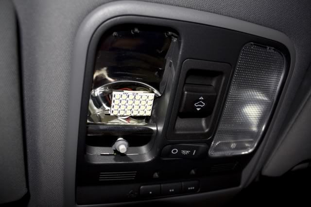
just saw this on another thread. Ima make PLCC-2 Boards for ALL my lights. got the images from SIXSIXFOUR.
Im not going to use 24 leds tho. it looks awesome. Oznium is going to get alot of business from AZ
01-12-2009, 12:18 AM
#57
01-12-2009, 12:57 AM
#58
wow.. Oznium is actually in san jose, which is where i am from.. it's too bad i dont have a clue about electrical wiring or what you guys are even talking about, lol... =(
this is a VERY VERY impressive mod infamous.. I've been always wanting my sidemarkers to blink at the same time as my head light blinkers.. even tho it's possible now, i wouldn't know how to do it. .. nice job tho!!!
this is a VERY VERY impressive mod infamous.. I've been always wanting my sidemarkers to blink at the same time as my head light blinkers.. even tho it's possible now, i wouldn't know how to do it. .. nice job tho!!!


 01-12-2009, 06:02 PM
#62
I ordered the LEDs last night and they shipped today. I got enough for 2 sets. Gerzand is really got me interested in his approach. Wish he would spill the beans. Where's the icon of the dog from the bushes baked beans commercial when you need it?!
Oh well, I don't mind soldering.
Oh well, I don't mind soldering.
01-12-2009, 07:05 PM
#63
Three Wheelin'
iTrader: (3)
I ordered the LEDs last night and they shipped today. I got enough for 2 sets. Gerzand is really got me interested in his approach. Wish he would spill the beans. Where's the icon of the dog from the bushes baked beans commercial when you need it?!
Oh well, I don't mind soldering.
Oh well, I don't mind soldering.
The idea is mine, all mine I tell you! muahahaha
\mad scientist

I just dont feel like having someone beat me to my own idea. im kinda greedy


 01-16-2009, 08:38 PM
#68
Hey Infamouslink, is it just me or are the white LEDs like 3 times brighter than the orange?
I've found a way to do the install without having the soldering be such a pain. When I get the test run done I'll post up a pic and explanation. Don't worry Evolicarus, I won't be doing the full sets till we can meet up. I'm just doing a trial run to make sure everything goes right. I don't want a wasted trip for which ever of us does the traveling.
I've found a way to do the install without having the soldering be such a pain. When I get the test run done I'll post up a pic and explanation. Don't worry Evolicarus, I won't be doing the full sets till we can meet up. I'm just doing a trial run to make sure everything goes right. I don't want a wasted trip for which ever of us does the traveling.
01-16-2009, 09:01 PM
#69
KBPftmfw
01-16-2009, 11:38 PM
#71
Chapter Leader (NY/NJ)
Thread Starter
iTrader: (10)
Hey Infamouslink, is it just me or are the white LEDs like 3 times brighter than the orange?
I've found a way to do the install without having the soldering be such a pain. When I get the test run done I'll post up a pic and explanation. Don't worry Evolicarus, I won't be doing the full sets till we can meet up. I'm just doing a trial run to make sure everything goes right. I don't want a wasted trip for which ever of us does the traveling.
I've found a way to do the install without having the soldering be such a pain. When I get the test run done I'll post up a pic and explanation. Don't worry Evolicarus, I won't be doing the full sets till we can meet up. I'm just doing a trial run to make sure everything goes right. I don't want a wasted trip for which ever of us does the traveling.
Yes white is brighter than the orange. i just got my second order from oznium the other day. my test set are still holding up good. just a reminder for you depending on how you like yours if you put the leds too close to the lens you'll be able to see the exact leds, try to keep them as far back as you can in order to get a even look accross the side marker. i also did both orange on top and white on top and so far i like the white on top depending on how you do your board. mine was all accross to get the even spread so on my second set that will hopefully be my last set, ima do 8 leds with white on top.
if you could tell me how you doing it either on here or via PM on how its easier without all the soldering, that would be great. that was i can see if your way would be easier for me before i start on my final set.
what i didn't mention earlier is that i bought plexiglass and made a new rear cover with 3 holes for the new connections becuz you cant use the stock harness. you need the extra wire for the incoming orange circuit.
thanks for sharing what you got so far too.Dont want to be like gerzand and keep everything private LOL.
i hope your idea works great gerzand and you let us all know how you doing it.
01-16-2009, 11:44 PM
#73
Chapter Leader (NY/NJ)
Thread Starter
iTrader: (10)
^^^
EDIT
ColorMCD (Min.)MCD (Typ.)Voltage (Min.)Voltage (Typ.)Wavelength
White 650 850 3.0 3.2 x=0.30 y=0.32
Orange 130 190 1.8 2.0 603
Yes white is brighter by 4X
EDIT
ColorMCD (Min.)MCD (Typ.)Voltage (Min.)Voltage (Typ.)Wavelength
White 650 850 3.0 3.2 x=0.30 y=0.32
Orange 130 190 1.8 2.0 603
Yes white is brighter by 4X
01-17-2009, 12:40 AM
#74
A little black book to store numbers in? Brilliant! Plexiglass back for the sidemarkers? Brilliant! Now where did I put my Guinness?
I have some left over Lexan that should work just fine for that. That means I wouldn't have to drill the holes that I did which means with my design going to 8 LEDs would not be a problem. I really wish I has a spare side marker to work with so I could perfect fitment and get a template made up.
I actually have several more ideas on how to do the soldering and even a way to do this without soldering. My dad used to be a wire man so I have to give him the credit for the method without soldering. Ok, I said I was going to wait till tomorrow to post up details, but darn it I already started so hear goes.
The test board is setup with a PC board with not copper contacts. I left 1 row of holes in between each LED. I took a small length of solid wire in a U shape and ran it up the two holes in between the LEDs. I bent 1 end of the wire to one LED and the other end to the other LED and soldered the wire to the LED. You'll see in the pic. I tested 2 different types of wire. Type 1 is the pre-cut and bent wire that you can get at radio shack for using with bread board. It was close to the right size but I had a concern that it may cause to much resistance so I only did 1 circuit of white and 1 of orange with this wire. The 2nd type of wire was solid copper 23 gage. I did the remaining white and orange circuits with this wire. Before anyone asks where I got the copper wire from.... I just wire my whole house with Cat6 solid network cable and I have some left so I cut a small length off and it worked nicely. I'm glad I tried the copper wire as well as my suspicions were well founded. The breadboard wire did increase the resistance and the lights were brighter. Infamouslink, I did do it your way on my first board and got the 2 white circuits done fine but messed up the 1st orange circuit. That's when I changed methods. This way is a little more time consuming to build but much easier to solder and is a lot cleaner. I'll do some comparison of the full solder method to the wire method to see if there is a noticeable change in brightness, at least for white. Below the pics I'll explain more into something my dad suggested that would allow use to easily put on 8 LEDs per color.
First pic is of top of board. The two bare wires you see coming out the ends are from two of the resistors mounted underneath.

This is the bottom. The tiny leads with the red sleeving were the bread board wires and the orange/brown/green/blue are the copper wire from the Cat6 cable. The bare contacts in the center with the green wire attached is the single ground point for all the circuits. The long orange wire will be used to bridge the two resistors for the orange LEDs and then I'll just solder the power lead to the orange wire (again from the Cat6 cable). The White/Orange wire is for the same purpose for the white LEDs.

As I was working on this I had talked to my dad some and explained what I was doing as he helped me do a set of the side markers for another forum member on here using the oznium module so he was familiar with what was needed. The biggest obstacle for people will be soldering the LEDs on. He said that there is a conductive glue that we could try. This glue is in liquid form until heat is applied to it and then it becomes solid and is conductive. This could be used to set and link the LEDs. The only thing he was not sure about was how much heat was required to set the glue. If this would work for us then we could basically put the LED right up against each other providing plenty of space.
Another option which I'm also considering it to get a PC board from radio shack that has a full plated copper side so you can build your own circuit paths. This would get us close to the glue method as you can build the contacts for the LEDs closer and then to solder it you would braze a copper wire, then set it down on the board with LEDs touching it on either side. Put the solder to it for a second to connect the LEDs to the wire and then snip the wire. That would allow for a very tight formation as well.
Wow, for not putting down details until tomorrow I sure did a poor job at waiting.
Hope this helps and makes sense.
I have some left over Lexan that should work just fine for that. That means I wouldn't have to drill the holes that I did which means with my design going to 8 LEDs would not be a problem. I really wish I has a spare side marker to work with so I could perfect fitment and get a template made up.
I actually have several more ideas on how to do the soldering and even a way to do this without soldering. My dad used to be a wire man so I have to give him the credit for the method without soldering. Ok, I said I was going to wait till tomorrow to post up details, but darn it I already started so hear goes.
The test board is setup with a PC board with not copper contacts. I left 1 row of holes in between each LED. I took a small length of solid wire in a U shape and ran it up the two holes in between the LEDs. I bent 1 end of the wire to one LED and the other end to the other LED and soldered the wire to the LED. You'll see in the pic. I tested 2 different types of wire. Type 1 is the pre-cut and bent wire that you can get at radio shack for using with bread board. It was close to the right size but I had a concern that it may cause to much resistance so I only did 1 circuit of white and 1 of orange with this wire. The 2nd type of wire was solid copper 23 gage. I did the remaining white and orange circuits with this wire. Before anyone asks where I got the copper wire from.... I just wire my whole house with Cat6 solid network cable and I have some left so I cut a small length off and it worked nicely. I'm glad I tried the copper wire as well as my suspicions were well founded. The breadboard wire did increase the resistance and the lights were brighter. Infamouslink, I did do it your way on my first board and got the 2 white circuits done fine but messed up the 1st orange circuit. That's when I changed methods. This way is a little more time consuming to build but much easier to solder and is a lot cleaner. I'll do some comparison of the full solder method to the wire method to see if there is a noticeable change in brightness, at least for white. Below the pics I'll explain more into something my dad suggested that would allow use to easily put on 8 LEDs per color.
First pic is of top of board. The two bare wires you see coming out the ends are from two of the resistors mounted underneath.
This is the bottom. The tiny leads with the red sleeving were the bread board wires and the orange/brown/green/blue are the copper wire from the Cat6 cable. The bare contacts in the center with the green wire attached is the single ground point for all the circuits. The long orange wire will be used to bridge the two resistors for the orange LEDs and then I'll just solder the power lead to the orange wire (again from the Cat6 cable). The White/Orange wire is for the same purpose for the white LEDs.
As I was working on this I had talked to my dad some and explained what I was doing as he helped me do a set of the side markers for another forum member on here using the oznium module so he was familiar with what was needed. The biggest obstacle for people will be soldering the LEDs on. He said that there is a conductive glue that we could try. This glue is in liquid form until heat is applied to it and then it becomes solid and is conductive. This could be used to set and link the LEDs. The only thing he was not sure about was how much heat was required to set the glue. If this would work for us then we could basically put the LED right up against each other providing plenty of space.
Another option which I'm also considering it to get a PC board from radio shack that has a full plated copper side so you can build your own circuit paths. This would get us close to the glue method as you can build the contacts for the LEDs closer and then to solder it you would braze a copper wire, then set it down on the board with LEDs touching it on either side. Put the solder to it for a second to connect the LEDs to the wire and then snip the wire. That would allow for a very tight formation as well.
Wow, for not putting down details until tomorrow I sure did a poor job at waiting.
Hope this helps and makes sense.
01-17-2009, 12:46 AM
#75
Oops forgot the mention that the reason I haven't finished up bridging the resistors across the back is that I'm going to pick up some silicon spray from Radioshack and spray it on the back to protect and to help protect against a possible short. I'm not really worried about a short as my solder skills are decent but why not add that little bit of protection in.
01-17-2009, 12:59 AM
#77
Chapter Leader (NY/NJ)
Thread Starter
iTrader: (10)
looks alot cleaner than mine, mine had solder everywhere lol but i bet it aint moving anywhere lol. about the glue your going to have to be very precise on where its applied, any smudge and you'll short out a led. good work tho. how do they look so far while on? remember to also cut a small groove when inserting in the side marker unless you plan on shaving the grooves off. cant read the resistors from the pics, just wanted to know what you ended up using? gerzand was also talking about instead of using a relay, he knew a way to make them blink like the switchbacks. i couldn't figure it maybe you know. all you have to do now is install in side marker run a wire from the corner light and watch your side markers match your switchbacks!!! cant wait to see the pics and hopefully a video.