
G-043: Blinking sidemarker DIY guide! Suitable for 3G garage?
 01-11-2010, 09:30 PM
#121
Instructor
Join Date: Nov 2008
Location: Doylestown, PA
Age: 45
Posts: 173
Likes: 0
Received 2 Likes
on
2 Posts
I think I screwed up the wiring....
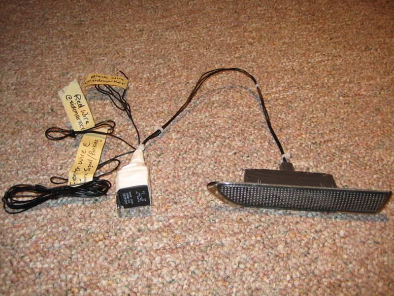
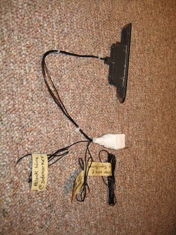
Something isn't right with my wiring. I'm confident I have the relay soldered correctly, I think I'm missing something on the connections. (SEE IMAGE)
Symptom: Turn signal works perfectly, side marker does not come on with lights nor does it blink with turn signal (no power)
If I touch the red wire that I cut (and joined with the respective wires from the relay) the side marker comes on with the lights, but it still does not blink with the turn signal.
Any thoughts????
 01-12-2010, 11:02 AM
#122
Three Wheelin'
Thread Starter
iTrader: (3)
^ I saw your PM's. From looking at the extension of my diagram that you created, I see 1 definite issue, and another thing that can be answered for sure using a voltmeter.
1) you need to reverse where the green and purple colored wires connect, respectively. "Harness side" refers to the wire that enters the firewall, NOT at the sidemarker itsself.
2) check your type-s turn signal wires using a volt meter to figure out which wire is supplying 12v ONLY on turn signal flash. Id check both issue areas before you use your car. Fixing one and not the other will probably blow your turn signal controller.
01-12-2010, 08:10 PM
#123
Instructor
Join Date: Nov 2008
Location: Doylestown, PA
Age: 45
Posts: 173
Likes: 0
Received 2 Likes
on
2 Posts
^ I saw your PM's. From looking at the extension of my diagram that you created, I see 1 definite issue, and another thing that can be answered for sure using a voltmeter.
1) you need to reverse where the green and purple colored wires connect, respectively. "Harness side" refers to the wire that enters the firewall, NOT at the sidemarker itsself.
2) check your type-s turn signal wires using a volt meter to figure out which wire is supplying 12v ONLY on turn signal flash. Id check both issue areas before you use your car. Fixing one and not the other will probably blow your turn signal controller.
1) you need to reverse where the green and purple colored wires connect, respectively. "Harness side" refers to the wire that enters the firewall, NOT at the sidemarker itsself.
2) check your type-s turn signal wires using a volt meter to figure out which wire is supplying 12v ONLY on turn signal flash. Id check both issue areas before you use your car. Fixing one and not the other will probably blow your turn signal controller.
GOT IT!!! Thanks so much for your help. The wire that needs tapped to at the turn signal bulb is indeed different on my 07 TL-S....the middle wire is the ground. It's working fine; now i just have to build the relay for the other side :-)
01-12-2010, 08:41 PM
#124
Three Wheelin'
Thread Starter
iTrader: (3)
Thats great... but as far as my point number "1" above..... did you just draw the diagram wrong or have you fixed this as well? Because how you have in the picture is very wrong and will supply no power to the sidemarker.
01-13-2010, 11:04 AM
#129
Three Wheelin'
Thread Starter
iTrader: (3)
There is nothing wrong with the current diagram....for 04-08 BASE model owners.
As stated, the only difference for Type-s owners is that turn signal sockets have a center wirewhich is grounded instead of 12v(on/off) when (blinking/not blinking).
Either use a voltmeter and figure out which one of the two remaining wires you need to tap into, or ask "spinxt" what color the wire was.
Maybe he will post that info here....
01-13-2010, 10:43 PM
#131
Relay Diagram
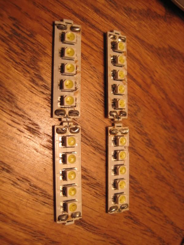
I finally got around to creating a set of 10 dual diode LED switchback sidemarkers. (Each LED blinks 2 colors).
I made this first set for another forum member so I'll have to make another set for myself yet still . Unfortunately, I don't have a complete guide yet for everyone to follow so bear with my until I make a second set.
There is however another discussion topic on the form about making these from your own LED's purchased in bulk:
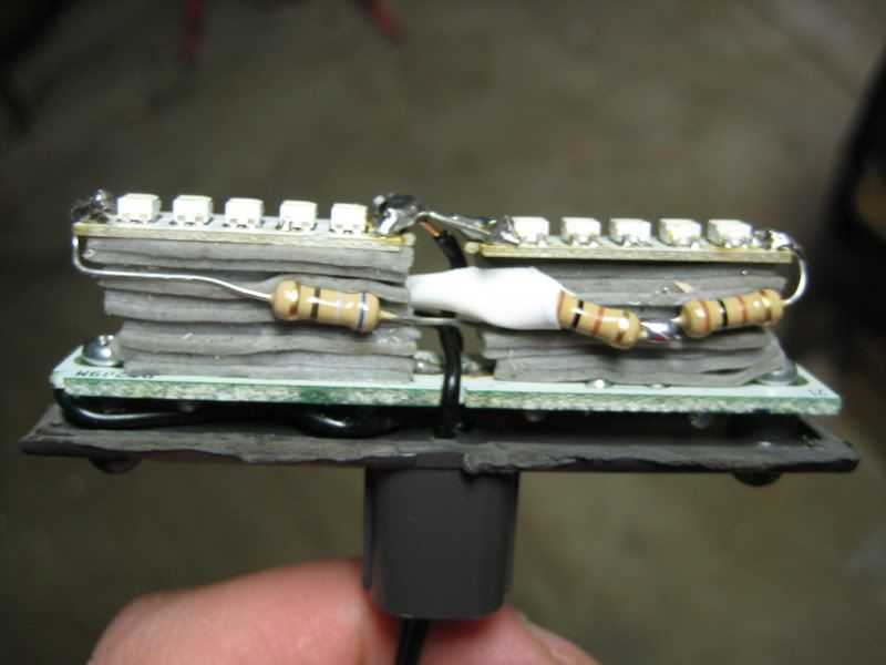
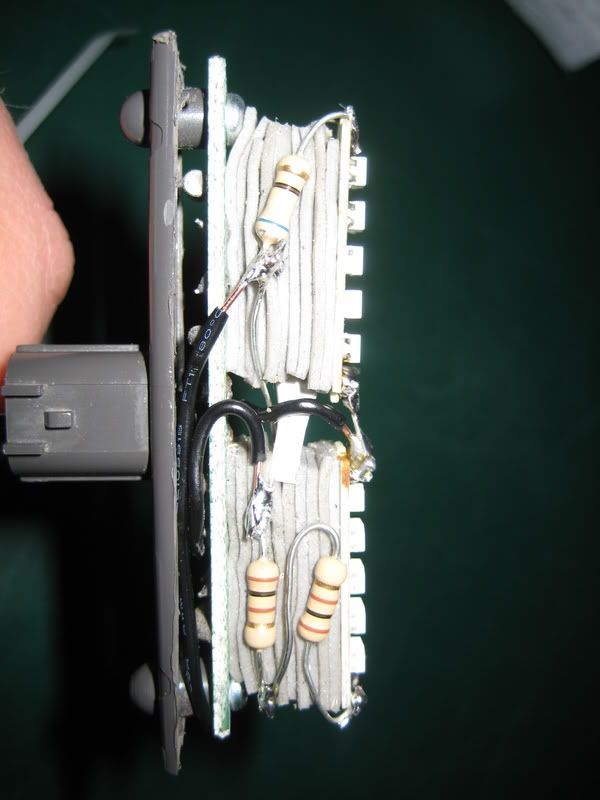
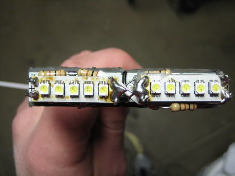
I created a pair of these by taking apart ONE 30 led switchback 7443 bulb from autolumination.com (approximate cost: $30 shipped), and wired it up inside a sidemarker using my own resistor values of (2) 100 ohm connected in series for each 5 amber Amber diodes, and 68ohm per each 5 LED White LED's. Also wired up is a relay to make it all work like a normal switchback bulb...
Enjoy the pics and videos
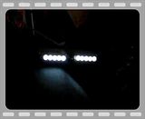
Video of completed switchback sidemarker:
In-progress video showing difference in White LED brightness with the car off @ 12.4v and on with the car on @14.3v:
I made this first set for another forum member so I'll have to make another set for myself yet still
. Unfortunately, I don't have a complete guide yet for everyone to follow so bear with my until I make a second set.There is however another discussion topic on the form about making these from your own LED's purchased in bulk:
I created a pair of these by taking apart ONE 30 led switchback 7443 bulb from autolumination.com (approximate cost: $30 shipped), and wired it up inside a sidemarker using my own resistor values of (2) 100 ohm connected in series for each 5 amber Amber diodes, and 68ohm per each 5 LED White LED's. Also wired up is a relay to make it all work like a normal switchback bulb...
Enjoy the pics and videos
Video of completed switchback sidemarker:
In-progress video showing difference in White LED brightness with the car off @ 12.4v and on with the car on @14.3v:
For those wondering how gerzand wired the relay here is the diagram:
You need a 5 pin relay (known as bosch relay) something like this , check ebay. The sidemarker has 3 wires: Negative, positive for Amber and positive for White.
Pin schematic:

1. Connect the negative wire from sidemarker to 85, and then another wire from 85 to black wire at the sidemarker connector (this is the negative imput).
2. Connect 86 to headlight turn signal bulb (center wire base TL, this is positive when blinker is on).
3. Connect 30 to red wire at the sidemarker connector ( this is positive when the parking lights are on)
4. Connect 87a to positive Amber
5. Connect 87 to positive White
2. Connect 86 to headlight turn signal bulb (center wire base TL, this is positive when blinker is on).
3. Connect 30 to red wire at the sidemarker connector ( this is positive when the parking lights are on)
4. Connect 87a to positive Amber
5. Connect 87 to positive White
However this only works with the parking lights on, if you turn off the parking lights the blinker will not work and nobody mentioned it yet.
If anyone figured out a way to work without parking lights please share. Please comment if you have any suggestions or comments
-ntuner
01-14-2010, 08:11 AM
#132
Instructor
Join Date: Nov 2008
Location: Doylestown, PA
Age: 45
Posts: 173
Likes: 0
Received 2 Likes
on
2 Posts
There is nothing wrong with the current diagram....for 04-08 BASE model owners.
As stated, the only difference for Type-s owners is that turn signal sockets have a center wirewhich is grounded instead of 12v(on/off) when (blinking/not blinking).
Either use a voltmeter and figure out which one of the two remaining wires you need to tap into, or ask "spinxt" what color the wire was.
Maybe he will post that info here....
As stated, the only difference for Type-s owners is that turn signal sockets have a center wirewhich is grounded instead of 12v(on/off) when (blinking/not blinking).
Either use a voltmeter and figure out which one of the two remaining wires you need to tap into, or ask "spinxt" what color the wire was.
Maybe he will post that info here....
01-14-2010, 09:21 PM
#133
Instructor
Join Date: Nov 2008
Location: Doylestown, PA
Age: 45
Posts: 173
Likes: 0
Received 2 Likes
on
2 Posts
-------------
Driver's Side--> Tap into the red wire with the blue stripe at turn signal bulb (not the center wire, which is a black ground).
I haven't done the passenger side yet, but I'm guessing the wire will be a different color. Easiest way to find it, is to take pull the harness out of the bulb housing, put the black probe of a volt meter in the center hole and put the red probe in either of the outside holes. When you find the one that shows 12volts ONLY when the turn signal is on, that's the wire you need to tap into.
02-06-2010, 07:03 PM
#134
Quick question... maybe I missed it in the past posts. My sidemarkers will only blink correct? They won't be on with the parking/short lights at all. if so is there a way to make them blink with the signals and when not being used as a blinker it'll stay on?
02-06-2010, 10:18 PM
#135
Instructor
Join Date: Nov 2008
Location: Doylestown, PA
Age: 45
Posts: 173
Likes: 0
Received 2 Likes
on
2 Posts
That's what this mod does....blinks with the turn signal, stays on with the parking/ headlights....if you only wanted it to blink, it would be easy....they blink/running light combo is the reason you need the relay...
02-07-2010, 02:06 PM
#137
well I didnt really have anything to do today so I made the relays for the sidemarkers. Of course when I get a good weekend with warm weather which will most likely be the spring time. Anyway I snapped a few pics of how my relays came out.
02-18-2010, 11:30 AM
#140
Instructor
Join Date: Aug 2007
Location: mo. city, texas
Age: 39
Posts: 144
Likes: 0
Received 0 Likes
on
0 Posts
i might of missed it but doesn't hurt to ask, Has anyone figured out a way to make the switchback side markers work without parking lights having to be on
02-18-2010, 12:24 PM
#141
02-18-2010, 03:18 PM
#142
Three Wheelin'
Thread Starter
iTrader: (3)
Here is a diagram I just drew up for you since it hasnt be clearly and concisely stated in the thread on how to go about this:
 03-10-2010, 11:07 PM
#145
Three Wheelin'
Thread Starter
iTrader: (3)
It all depends on the resistance values you use for the LEDs. Amber needs less power than the white to operate. Best thing to do it to use a resistance calculator online taking into consideration the stepdown voltage (whether in series or parallel). I forget my values, but my ambers are equally as bright, if not brighter than the white.
03-10-2010, 11:16 PM
#146
2005 AM at/navi
this mod is cool i didnt know it was possible i wish i had the time is anybody willing to make some for me ill buy what is needed and we can work out a price if possibke then ill assemble it myself....???
03-11-2010, 01:54 AM
#147
Drifting

Why do you need Diodes on the power source and the switching circuit of the relay? And why did you connect both together? You don't need those diodes. The main feature of diodes is to allow current to flow one direction. Nodes 85 and 86 are completely separate from 30. You may not understand how the relay works.You dont need to connect 85 to 30. When node 85 is energized, the internal coil causes a magnetic field to cause the the source (30) voltage to move from 87a to 87.
what you guys really need to do is put the parking lights (12v) on the 30 node so that 87a stays on normally while 85 is NOT energized. Then connect the 85 to the actual blinker circuit so that when the switching circuit of the relay (85 to 86) is energized, then the relay switches the source to node 87. That way the side markers will flash amber in sequence with the front blinkers.

what you guys really need to do is put the parking lights (12v) on the 30 node so that 87a stays on normally while 85 is NOT energized. Then connect the 85 to the actual blinker circuit so that when the switching circuit of the relay (85 to 86) is energized, then the relay switches the source to node 87. That way the side markers will flash amber in sequence with the front blinkers.
The key to accomplish this is the use of one-way voltage regulating diodes. The radioshack part # is listed on the first post of this thread, as it is used in the blinking sidemarker diagram I posted.
Here is a diagram I just drew up for you since it hasnt be clearly and concisely stated in the thread on how to go about this:
Here is a diagram I just drew up for you since it hasnt be clearly and concisely stated in the thread on how to go about this:
Last edited by Chad05TL; 03-11-2010 at 01:57 AM.
 03-11-2010, 06:40 AM
#148
Three Wheelin'
Thread Starter
iTrader: (3)
Hey bud, thanks for the lesson in the science of a relay...but you need to ask youself something. In your diagram, would the sidemarker would blink if the parking lights weren't on? That's not full functionality my man.
03-11-2010, 07:04 AM
#149
Three Wheelin'
Thread Starter
iTrader: (3)
Just noticed I misworded 85 in my hand drawn diagram. It needs to say blinker 12v. Still doesn't change the fact that u still need rectifier diodes to control direction of voltage flow for this application, though.
03-11-2010, 08:47 AM
#151

I think the OP stated earlier that he might make these for $$. PM him.
03-11-2010, 10:49 AM
#152
Drifting
no you dont need diodes. So, take off the parking lights comment but leave it as Constant 12v like I mentioned. my diagram fixes your amber illumination time to be illuminated when your front blinker is on. You guys have it backwards in the VIDEO. Also I can tell you how to use the side marker as a running light at night AND also a blinker for day use and night use. But I'll let you smart guys figure it out. haha is that handled well enough for ya?
03-11-2010, 10:51 AM
#153
Drifting
the relay is designed to handle 12v of a car. Again I say, you dont need diodes. If so, then all your stupid electronics on your car would need diodes. haha
03-11-2010, 02:16 PM
#154
Drifting
well after looking at a 1 or 2 relay solution to have the Parking lights operational *AND* having the blinkers work when the parking lights are on or off is not going to be possible with 1 or even 2 spdt relays in series. I think digital logic or a microprocessor would be required to have the parking lights work on the side markers while having the amber light illuminate at the same time the front blinkers do.
The only thing close to having parking lights and a blinker all in one, would be to have 2 separate colors like your white and amber connected to one SPDT switch but have the white on 87A and amber on 87, just like Gerzand already indicated in his drawing. So the white would be like a "daytime running light". That may be ok for a 07 or 08, but my 05 doesnt have DRL. So, it wouldnt look right to have the white on all the time. And there wont not be a way to leave the white on as parking lights unless you have a completely separate circuit. But if you have a completely separate circuit, then you would need to figure out a way to shut off the white when the amber comes on. My 1997 camaro used to do that very thing, but it had a brain or a "microprocessor" that was programmed to output a certain thing when the input was a certain condition. Anyways, theres a lot of different senarios, but nothing really did what I wanted it to do. Its easy to get it to work as parking lights or a blinker, but to do both with just 1 or 2 relays may not be possible. At least I have not been able to find the right solution in 2 hours.
As far as Gerzand schematic, I think it's right except for the diodes. The amber should be coming on the same time the amber comes on , on the front blinkers.. but in the video its reversed. So, I think something funky is going on with tieing the 85 & 30 together. OR MAYBE his lights are not soldered properly to 87 and 87a. at least that way all the amber lights would come on at the same time. But I dont think anyone can have parking lights funtional to be on and off, and also having the blinkers work when the parking lights are on or off, unless you use a microprocessor, which only works on 5v rather than 12. They do make relays that switch 12 volts by a 5v reference, so all this can be done, but you would have to geta little black box and basically create a brain for it. Either way, to me this is a waste of time. And i've already spent too much time even thinking about it. I gotta go work out. haha
Last edited by Chad05TL; 03-11-2010 at 02:19 PM.
03-11-2010, 04:02 PM
#155
Three Wheelin'
Thread Starter
iTrader: (3)
ya your damn right it should say blinker and not parking lights. I was trying to figure oout why you were connecting the parking lights to 12v harness with diodes! wtf is that? you dont connect 85 to 30. you must not know how the relay works inside!!
the relay is designed to handle 12v of a car. Again I say, you dont need diodes. If so, then all your stupid electronics on your car would need diodes. haha
the relay is designed to handle 12v of a car. Again I say, you dont need diodes. If so, then all your stupid electronics on your car would need diodes. haha
well after looking at a 1 or 2 relay solution to have the Parking lights operational *AND* having the blinkers work when the parking lights are on or off is not going to be possible with 1 or even 2 spdt relays in series. I think digital logic or a microprocessor would be required to have the parking lights work on the side markers while having the amber light illuminate at the same time the front blinkers do.
The only thing close to having parking lights and a blinker all in one, would be to have 2 separate colors like your white and amber connected to one SPDT switch but have the white on 87A and amber on 87, just like Gerzand already indicated in his drawing. So the white would be like a "daytime running light". That may be ok for a 07 or 08, but my 05 doesnt have DRL. So, it wouldnt look right to have the white on all the time. And there wont not be a way to leave the white on as parking lights unless you have a completely separate circuit. But if you have a completely separate circuit, then you would need to figure out a way to shut off the white when the amber comes on. My 1997 camaro used to do that very thing, but it had a brain or a "microprocessor" that was programmed to output a certain thing when the input was a certain condition. Anyways, theres a lot of different senarios, but nothing really did what I wanted it to do. Its easy to get it to work as parking lights or a blinker, but to do both with just 1 or 2 relays may not be possible. At least I have not been able to find the right solution in 2 hours.
As far as Gerzand schematic, I think it's right except for the diodes. The amber should be coming on the same time the amber comes on , on the front blinkers.. but in the video its reversed. So, I think something funky is going on with tieing the 85 & 30 together. OR MAYBE his lights are not soldered properly to 87 and 87a. at least that way all the amber lights would come on at the same time. But I dont think anyone can have parking lights funtional to be on and off, and also having the blinkers work when the parking lights are on or off, unless you use a microprocessor, which only works on 5v rather than 12. They do make relays that switch 12 volts by a 5v reference, so all this can be done, but you would have to geta little black box and basically create a brain for it. Either way, to me this is a waste of time. And i've already spent too much time even thinking about it. I gotta go work out. haha
The only thing close to having parking lights and a blinker all in one, would be to have 2 separate colors like your white and amber connected to one SPDT switch but have the white on 87A and amber on 87, just like Gerzand already indicated in his drawing. So the white would be like a "daytime running light". That may be ok for a 07 or 08, but my 05 doesnt have DRL. So, it wouldnt look right to have the white on all the time. And there wont not be a way to leave the white on as parking lights unless you have a completely separate circuit. But if you have a completely separate circuit, then you would need to figure out a way to shut off the white when the amber comes on. My 1997 camaro used to do that very thing, but it had a brain or a "microprocessor" that was programmed to output a certain thing when the input was a certain condition. Anyways, theres a lot of different senarios, but nothing really did what I wanted it to do. Its easy to get it to work as parking lights or a blinker, but to do both with just 1 or 2 relays may not be possible. At least I have not been able to find the right solution in 2 hours.
As far as Gerzand schematic, I think it's right except for the diodes. The amber should be coming on the same time the amber comes on , on the front blinkers.. but in the video its reversed. So, I think something funky is going on with tieing the 85 & 30 together. OR MAYBE his lights are not soldered properly to 87 and 87a. at least that way all the amber lights would come on at the same time. But I dont think anyone can have parking lights funtional to be on and off, and also having the blinkers work when the parking lights are on or off, unless you use a microprocessor, which only works on 5v rather than 12. They do make relays that switch 12 volts by a 5v reference, so all this can be done, but you would have to geta little black box and basically create a brain for it. Either way, to me this is a waste of time. And i've already spent too much time even thinking about it. I gotta go work out. haha
Where the hell did this guy come from?
 Its as if he doesnt believe the wheel turns, and is trying to re-invent it.
03-11-2010, 04:56 PM
Its as if he doesnt believe the wheel turns, and is trying to re-invent it.
03-11-2010, 04:56 PM
#156
Drifting
ya it works backwards. at least it doesn't in my opinion. amber lights up on the front, and your side marker turns white. Good job genius. thats what you call jerry rigging.
03-11-2010, 05:04 PM
#157
Drifting
so does the white light stay on all the time like daytime running lights?
03-11-2010, 06:32 PM
#158
Instructor
Join Date: Aug 2007
Location: mo. city, texas
Age: 39
Posts: 144
Likes: 0
Received 0 Likes
on
0 Posts
i can vouch for gerzand instructions that they work. i also used the diodes and my switchback sidemarkers work like they are suppose too. during the day without any parking lights or headlights on the side marker isn't on but when the parking lights are on so are the sidemarkers and when you hit your turn signal the switchback sidemarker flash just like the front turn signal switchbacks at the same time.
03-11-2010, 07:13 PM
#160
Chapter Leader (NY/NJ)
iTrader: (10)
obviously you dont even know how the switchback bulbs work in themselves so heres a quick lesson.
When off they are OFF
when parking lights are on they are white
when signaling no matter if the parking lights are on or off- they blink amber
By doing my wiring configuration WITH the diodes, you are able to EXACTLY mimic the switchbacks that are in your headlights.
If you have any doubts and since you seem to be full of yourself and your knowledge on how $hit works, look at the schematic.
Just in case you need an explanation of the schematic:
87a - White output of side markers
87 - Amber output of side markers
86 - Ground
85 - Turn Signal +
30 - Parking lights +
Then 2 diodes Cathodes facing same direction connecting the Turn Signal + and the Parking lights +
The reason for the diodes is to block the + to the Parking lights when you signal when the parking lights are NOT on and also to block the + signal from the parking lights when you are NOT signaling. Without diodes, when you signal, your parking lights will also turn on if they were off to begin with, and vice versa, when you turn on the parking lights, this will cause the relay to close and turn your sidemarker amber while your fronts are white ( SAME AS STOCK)
If you have any doubts, then you dont know what you doing and should pay someone to do this for you before you short out your car.
http://www.youtube.com/watch?v=yMmoXOSSkkM
Last edited by InFaMouSLink; 03-11-2010 at 07:16 PM.