DIY: Install Resistors
 09-18-2011, 04:45 PM
#1
ROTAREDOM
Thread Starter
DIY: Install Resistors
So if you have installed LED lights for your turn signals you may or may not be hyper-flashing.If you are, this DIY will fix that problem. DISCLAIMER: This is only intended as a guide, I will not be held responsible for any damage that may happen to your car. Now that we have that out of the way lets begin...
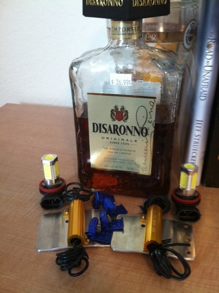
We will need 6 OHM 50 W 2 Blubl LED Load Equalizer Resistors. I bought mine from V-LEDS for about $13.( It also comes with 4 scotchloks) Disaronno is optional lol.
Other tools:
10mm socket wrench
screw driver
pliers
scissors
electrical tape
3M double sided tape
Cups( to separate the clips from your bumper, headlight etc...)
Remove your bumper (not gunna explain that one)
Now remove your headlight (thanks Kowloon)
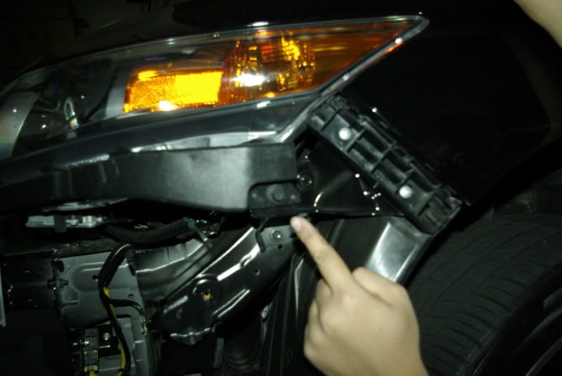
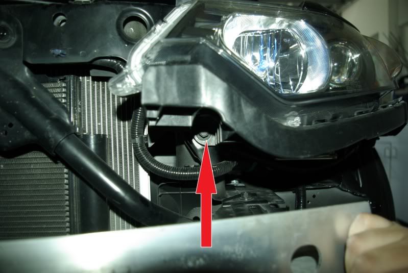
Now locate the wires going to your turn signal, it will look like this
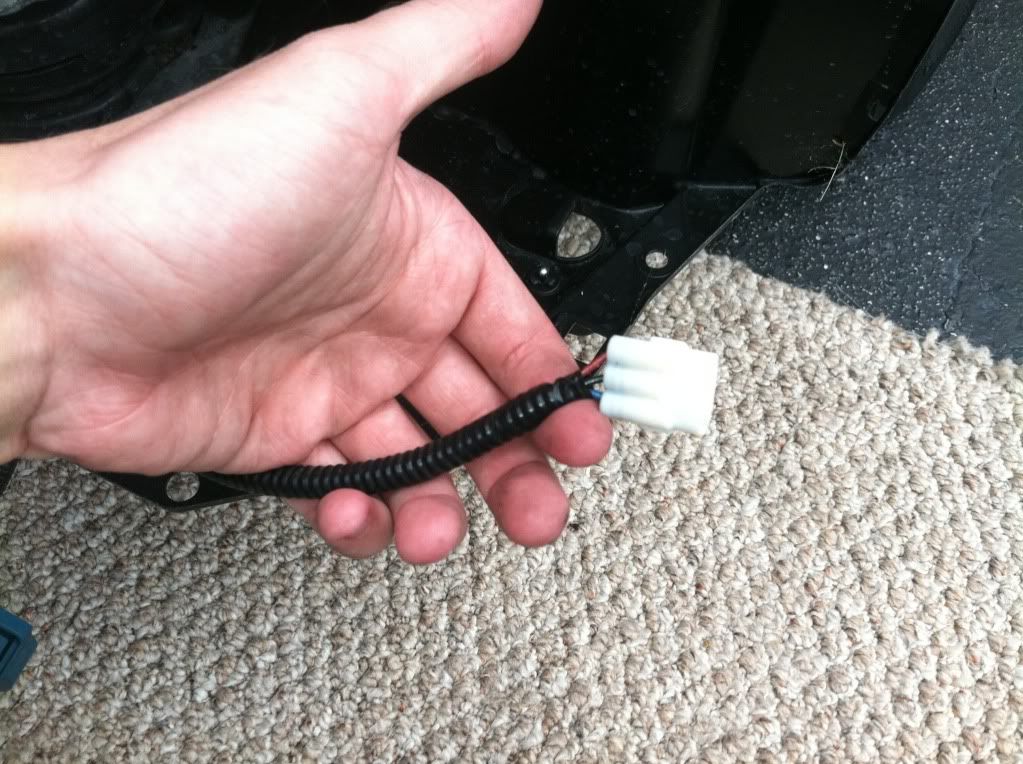
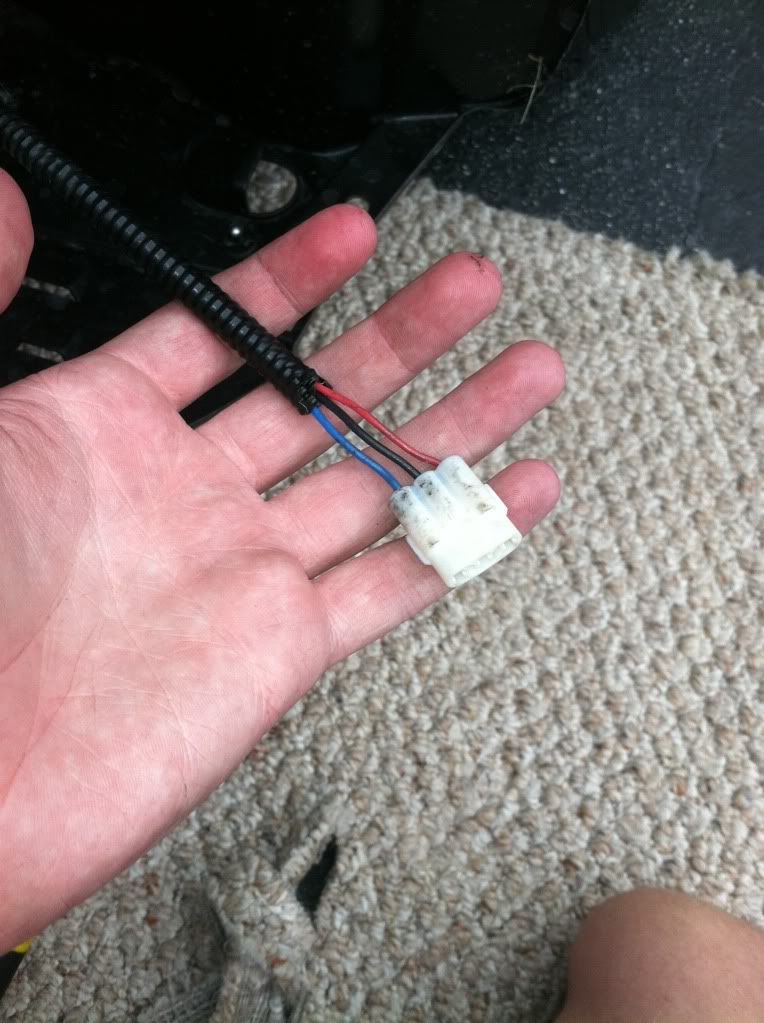
Now carefully expose about 2 inches of wire using scissors.
Now if you have never used scotchlok here is a diagram and video.
http://www.v-leds.com/BlinkerWarning...p8726800.html#
I started with the left light (driver side) so we are going to tap into blue wire first then black (our ground)
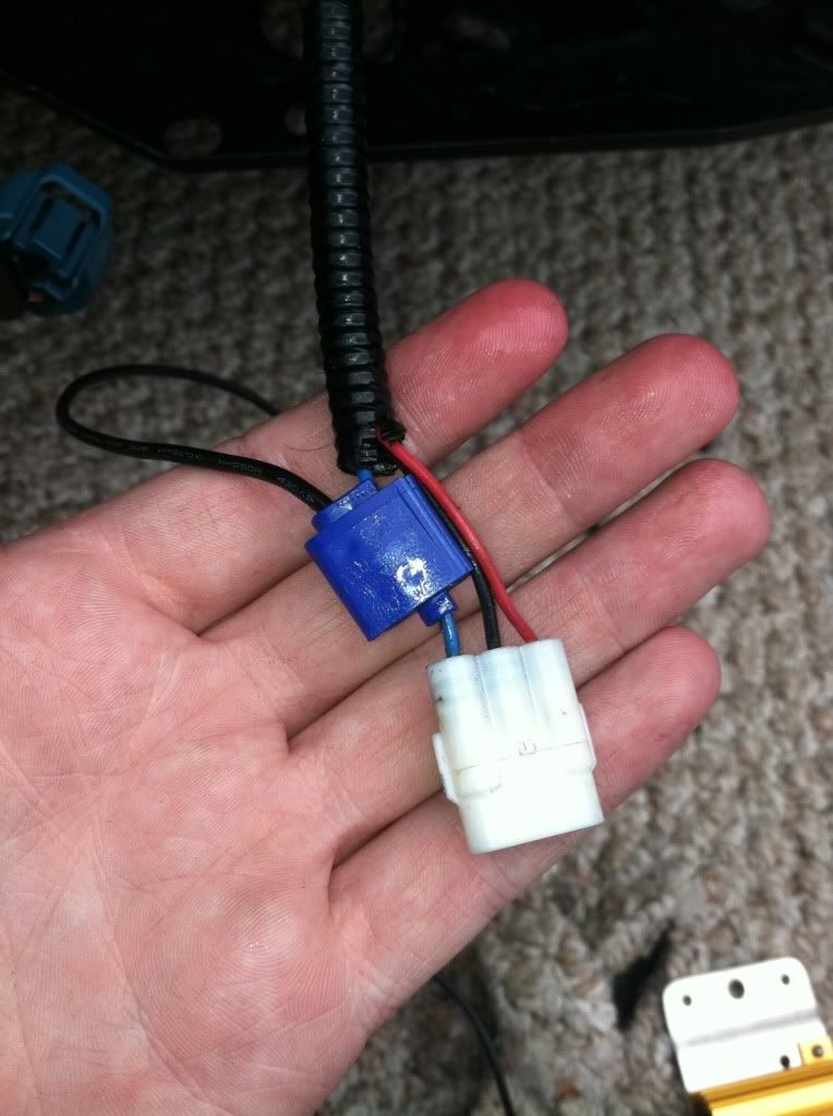
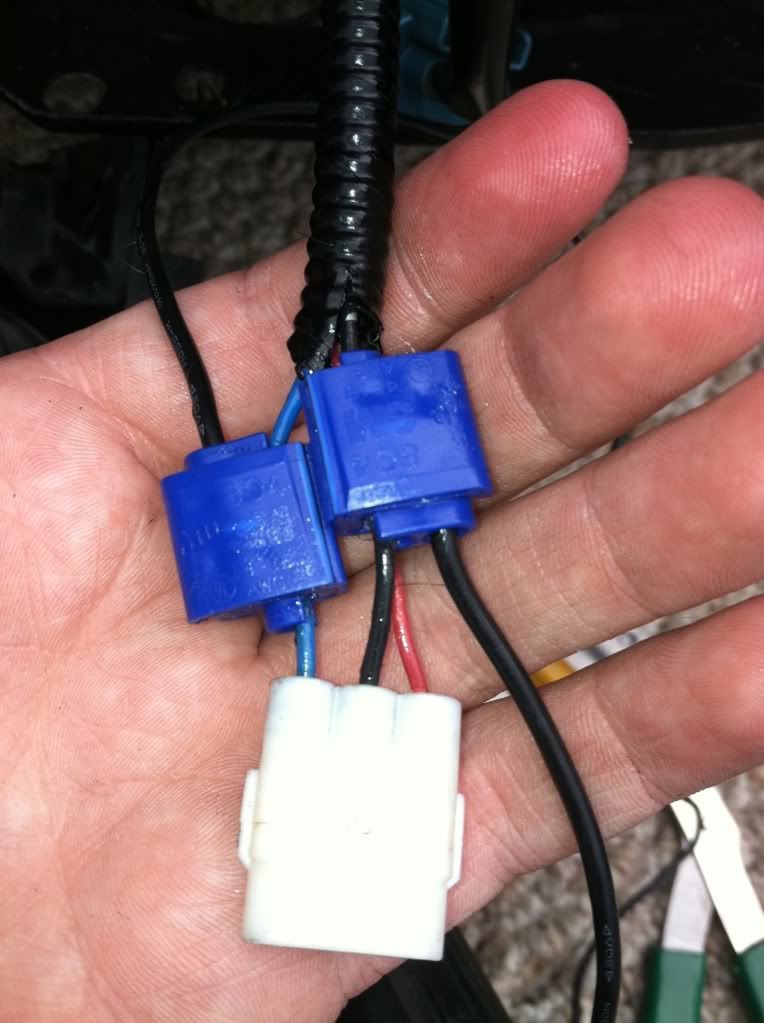
Now test your turn signal to see if it is still hyper-flashing. NOTE: Don't be generous with the amount of pressure you apply the with the pliers, remember the small metal piece has to make a connection with the copper to work) If all goes well your turn signal should be blinking at the normal rate. Now do the same thing for the right side turn signal ( wires will be green and black)
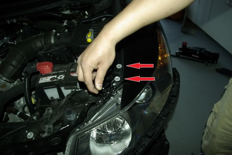
Now when putting your headlight back fee your resistor up through the gap of the metal between the body. Hard to explain but you will understand when you do it. Now cut two pieces of double sided tape and mount your resistor.
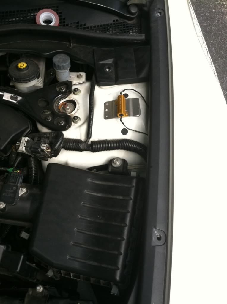
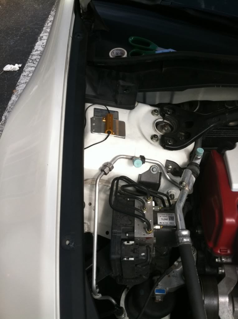
Because I used 3M tape I mounted mine on a flat surface. You don't have to do this but it is very easy and out of the way from any moving parts. Also I used electrical tape to clump the two wires together so they weren't just dangling freely. And here is the final result.
We will need 6 OHM 50 W 2 Blubl LED Load Equalizer Resistors. I bought mine from V-LEDS for about $13.( It also comes with 4 scotchloks) Disaronno is optional lol.
Other tools:
10mm socket wrench
screw driver
pliers
scissors
electrical tape
3M double sided tape
Cups( to separate the clips from your bumper, headlight etc...)
Remove your bumper (not gunna explain that one)
Now remove your headlight (thanks Kowloon)
Now locate the wires going to your turn signal, it will look like this
Now carefully expose about 2 inches of wire using scissors.
Now if you have never used scotchlok here is a diagram and video.
http://www.v-leds.com/BlinkerWarning...p8726800.html#
I started with the left light (driver side) so we are going to tap into blue wire first then black (our ground)
Now test your turn signal to see if it is still hyper-flashing. NOTE: Don't be generous with the amount of pressure you apply the with the pliers, remember the small metal piece has to make a connection with the copper to work) If all goes well your turn signal should be blinking at the normal rate. Now do the same thing for the right side turn signal ( wires will be green and black)
Now when putting your headlight back fee your resistor up through the gap of the metal between the body. Hard to explain but you will understand when you do it. Now cut two pieces of double sided tape and mount your resistor.
Because I used 3M tape I mounted mine on a flat surface. You don't have to do this but it is very easy and out of the way from any moving parts. Also I used electrical tape to clump the two wires together so they weren't just dangling freely. And here is the final result.

The following 6 users liked this post by ssjoeboe9:
Drull (09-19-2011),
ed_423 (09-19-2011),
KillerG (09-18-2011),
MrOtocinclus (09-18-2011),
saucy (09-19-2011),
and 1 others liked this post.
09-18-2011, 07:26 PM
#4
ROTAREDOM
Thread Starter
damn, I made some spelling errors haha... yall get the idea though.
09-18-2011, 08:48 PM
#5
this wont get alot of attention but its a valuable piece of knowledge for the TSX community and will help alotta people
my thanks to you!
my thanks to you!
09-18-2011, 09:58 PM
#6
ROTAREDOM
Thread Starter
No problem guys! It's always good to have the most information you can on a subject, especially when it involves wires and electricity!
Trending Topics
 09-18-2011, 11:12 PM
#10
ROTAREDOM
Thread Starter
BTW... I left both blinkers on for over 2 minutes each and although the resistors themselves get super hot it dissipates pretty quickly. There is about a 1cm gap (I'm guessing) between the heat resistant shield on the hood and the resistor when the hood is closed.After my inspection there was no heat damage to the shield or anything around it(as expected).
 red at the base, whte across. haha
09-19-2011, 10:50 AM
red at the base, whte across. haha
09-19-2011, 10:50 AM
#12
ROTAREDOM
Thread Starter
^ You wanna photoshop that for me?

 09-19-2011, 05:40 PM
#15
ROTAREDOM
Thread Starter
 09-19-2011, 06:48 PM
#17
ROTAREDOM
Thread Starter
May consider down the road... I like cheap mods! and I'm pretty good with paint lol.
06-10-2012, 05:01 PM
#18
Good DIY. Im gonna use this soon to install my resistors. TY JOE
06-10-2012, 05:20 PM
#19
ROTAREDOM
Thread Starter
No problem ttk. Hope all goes well with the install! 
 06-12-2012, 02:13 PM
#21
I got everything working. For the passenger side, the green wire is equivalent to the blue wire for anyone who attempts this. Also, if your resistors have red AND black wires, I dont think it matters which end you put where. I think. correct me if im wrong. And like you said joe, remember to clamp the blue things down hard so the metal penetrates fully.
06-12-2012, 02:57 PM
#22
Everyday I'm rofling
I got everything working. For the passenger side, the green wire is equivalent to the blue wire for anyone who attempts this. Also, if your resistors have red AND black wires, I dont think it matters which end you put where. I think. correct me if im wrong. And like you said joe, remember to clamp the blue things down hard so the metal penetrates fully.
Full penetration is always a good idea!
The following users liked this post:
ed_423 (06-12-2012)
06-12-2012, 03:21 PM
#23
Indeed! Full penetration!
The following 2 users liked this post by ttk5:
ed_423 (06-12-2012),
opboarding (06-12-2012)
06-12-2012, 05:25 PM
#24
ROTAREDOM
Thread Starter
lol yessss deeep penetration through the rubber is required.

Thread
Thread Starter
Forum
Replies
Last Post
cycdaniel
1G TSX Performance Parts & Modifications
8
12-17-2019 10:58 AM
Greengecko
3G TL Audio, Bluetooth, Electronics & Navigation
4
09-16-2015 08:19 PM