When you click on links to various merchants on this site and make a purchase, this can result in this site earning a commission. Affiliate programs and affiliations include, but are not limited to, the eBay Partner Network.
I am in over my head. I've successfully removed + cleaned my throttle body, plenum, intake manifold, removed/replaced the EGR and idle air control valves, and started to reassemble, but am now stumped. The electrical and the accelerator + cruise control throttle cables (and a third cable I assume goes to a throttle position sensor), were not too bad, however I am hopelessly confused on vacuum hose/fuel line routing! I haven't disturbed "the other end" of any vacuum lines, but there are five or six small diameter lines terminating at or near the throttle body that I foolishly assumed I could reconnect based on their proximity and orientation to vacuum ports; clearly, I was WRONG. I've now spent two days reading countless threads in "Gen 2 TL problems and fixes" and the DIY section, but the various bits I found are not enough. Finishing a thread with "just reverse this procedure" hasn't been helpful. I do not have a service manual. Can a complete vacuum line diagram be found anywhere on this site? If not, where may I buy/steal one?
At this point, without a detailed vacuum line diagram, I am torn between towing this rolling dumpster fire somewhere for reassembly by a qualified service technician, or just donating it...
Take a picture and I can tell you where each line goes. You can also find the service manual for free if you search for it. Honestly, I'm surprised you're having any difficulty as the lines have a "memory" of where they should go, and usually they can only reach to one spot.
Thank you both, KARANX7 and Zeta! The diagrams helped greatly! Unfortunately, I still found away to eff it up badly. I invite you both to read the related threads dated Feb 26. ANY further suggestions or guidance is welcome. Thank you!
I am in over my head. I've successfully removed + cleaned my throttle body, plenum, intake manifold, removed/replaced the EGR and idle air control valves, and started to reassemble, but am now stumped. The electrical and the accelerator + cruise control throttle cables (and a third cable I assume goes to a throttle position sensor), were not too bad, however I am hopelessly confused on vacuum hose/fuel line routing! I haven't disturbed "the other end" of any vacuum lines, but there are five or six small diameter lines terminating at or near the throttle body that I foolishly assumed I could reconnect based on their proximity and orientation to vacuum ports; clearly, I was WRONG. I've now spent two days reading countless threads in "Gen 2 TL problems and fixes" and the DIY section, but the various bits I found are not enough. Finishing a thread with "just reverse this procedure" hasn't been helpful. I do not have a service manual. Can a complete vacuum line diagram be found anywhere on this site? If not, where may I buy/steal one?
At this point, without a detailed vacuum line diagram, I am torn between towing this rolling dumpster fire somewhere for reassembly by a qualified service technician, or just donating it...
this vacuum line is disconnected on my car, don�t know where it goes, please help me
Take a picture and I can tell you where each line goes. You can also find the service manual for free if you search for it. Honestly, I'm surprised you're having any difficulty as the lines have a "memory" of where they should go, and usually they can only reach to one spot.
Hi can you please help me with vacuum switch value line. It is disconnected don�t know where it fits. One side is connected to this part.
^
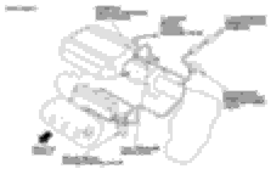
#17 connects to the bottom of the #5 front engine mount via #16 & 13 respectively. (refer to the part diagram below)
#28 connects to the bottom of the #6 rear engine mount via #15 & 14 respectively.
Keep in mind, if the front and rear engine mounts have been replaced, in the past, with 'aftermarket' mounts, they
may not have the vacuum ports like the OEM ones that came with the car; thus, explaining why these tubes may be disconnected?
^
#17 connects to the bottom of the #5 front engine mount via #16 & 13 respectively. (refer to the part diagram below)
#28 connects to the bottom of the #6 rear engine mount via #15 & 14 respectively.
Keep in mind, if the front and rear engine mounts have been replaced, in the past, with 'aftermarket' mounts, they
may not have the vacuum ports like the OEM ones that came with the car; thus, explaining why these tubes may be disconnected?
yes, engine mount got replaced last year, mechanic put a used one. What should I do now, just leave these lines like this?
yes, engine mount got replaced last year, mechanic put a used one. What should I do now, just leave these lines like this?
1) If you have the skillset to trace the vacuum line route(s), based on the part diagram provided, empower yourself & determine if the front and rear mounts have the ports, hook them up, save yourself some $$.
2) Pay your mechanic $$ to revisit his work and connect the vacuum line(s) correctly.
3) Plug all open ends of the tubes to stop vacuum leaks from occurring & tuck the tubing out of the way?
Good Luck
 02-20-2022, 03:59 PM

 . I've now spent two days reading countless threads in "Gen 2 TL problems and fixes" and the DIY section, but the various bits I found are not enough. Finishing a thread with "just reverse this procedure" hasn't been helpful. I do not have a service manual. Can a complete vacuum line diagram be found anywhere on this site? If not, where may I buy/steal one?