When you click on links to various merchants on this site and make a purchase, this can result in this site earning a commission. Affiliate programs and affiliations include, but are not limited to, the eBay Partner Network.
Yo Acurazine. As a penance for my ridiculous post this morning, I decided to try and fix my display and post the pictures. I was very hesitant for fear that I would break something, but it went smoothly. Thanks to all who posted previous pics and tips; you gave me the courage to attempt this.
1. Gently pull up at the left and front corners of display. Take your time and be gentle, the front will come up.
2. While the front is coming up, work your hands to the rear and pull up there as well.
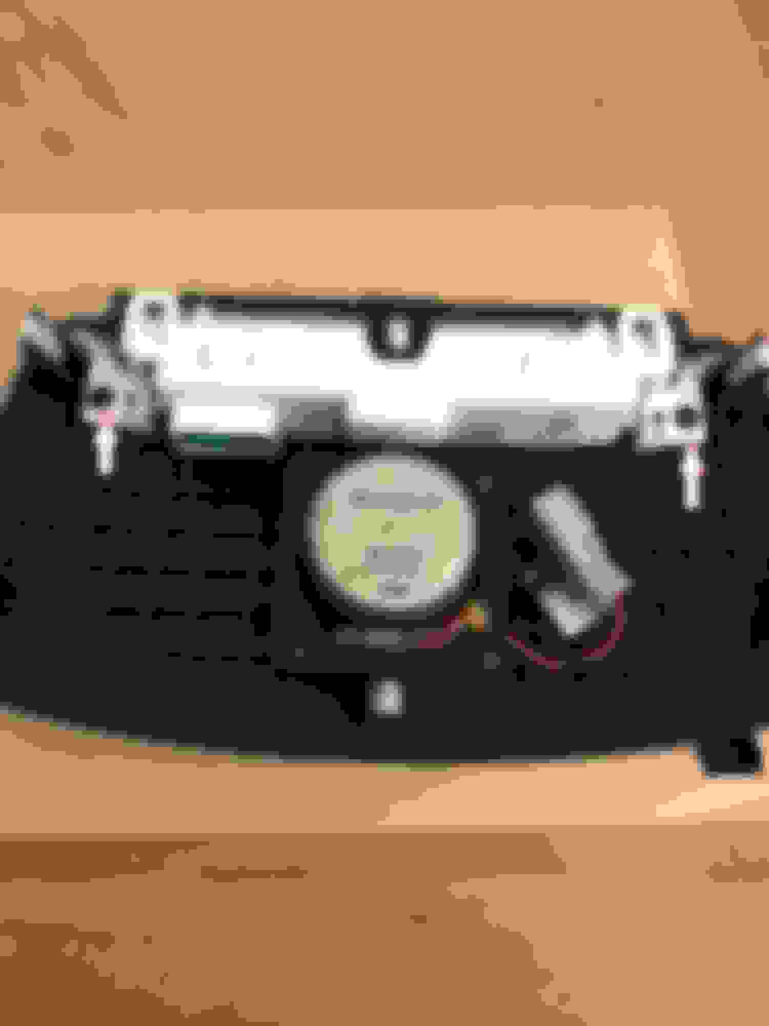
This is the unit. Note the clips at the 4 corners.
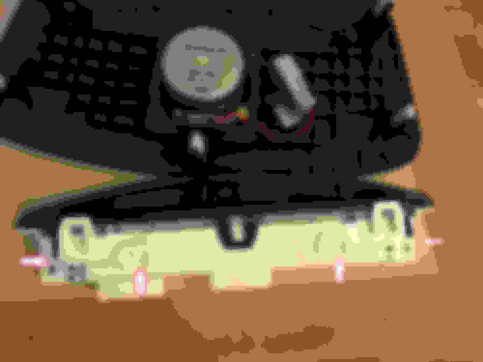
3. Unclip the jack to the speaker and the block connector to the display unit.
Better view of display connection. On both, you have to squeeze down on a release tab, Pull out easy and take your time. (That's what she said.)
4.Unscrew the display from the housing. There is a screw on each side of the white case but they are not shown in pic below.
5. Then, I took a thin knife and unclipped the 4 tabs. I just slid the knife under the tab and GENTLY lifted up to release all 4 tabs.
6. Then gently remove the black material from the other side to expose the tabs under it and pry those up as well.
7. Now gently pull up on the connector a little bit to release the thin ribbon connection my finger is pointing to. You release it via the connector, then pull the white part up and out.
8. Now pull up on the 4 clips to release the circuit board.
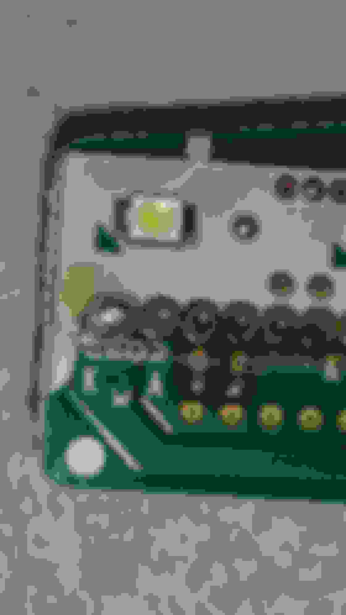
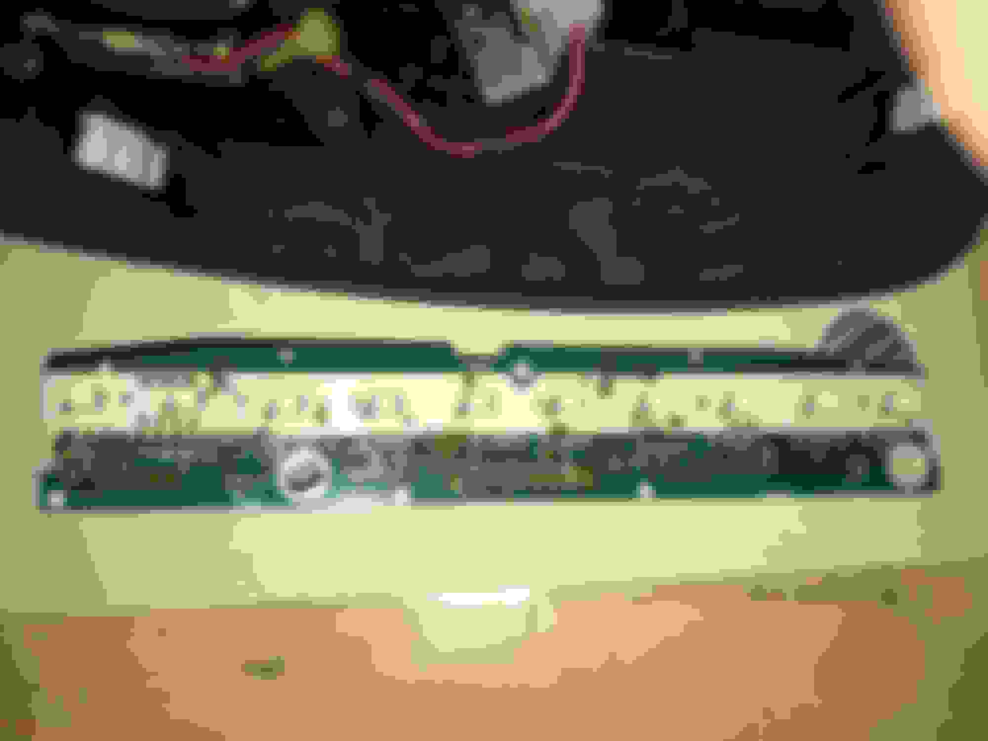
Above is FRONT of display board.
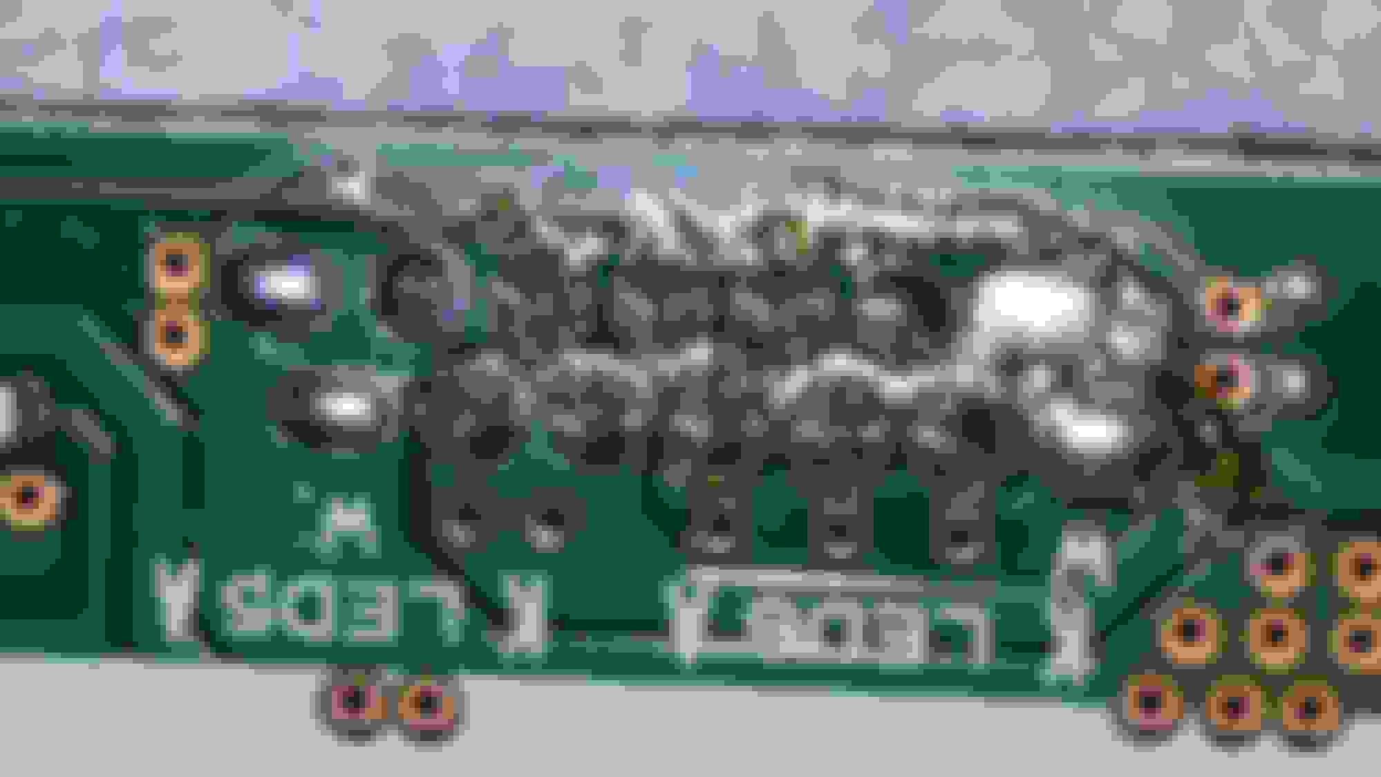
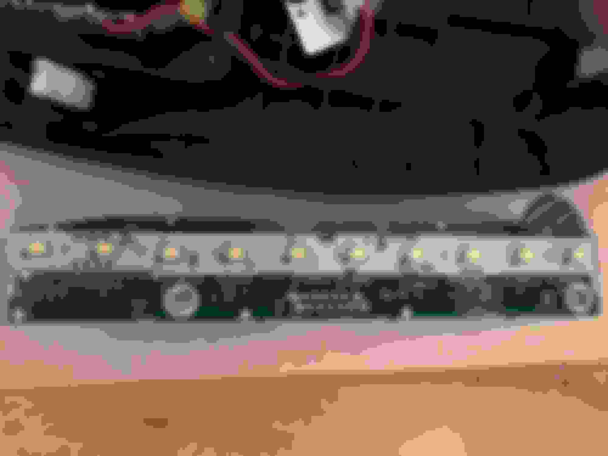
Note the terrible cold solder joint over the word "LED" on the REAR of display board. This is what is causing the issue. Terrible soldering all around.
Either do it yourself or have a computer shop reflow or dab the cold\bad points with some solder.
Wow.
I lucked out and only had to wedge a little rubber piece right under the green connector on the left side, then screwed the display down to housing. Hopefully your fix will be as simple.
Tested it and it came right on; no more tapping the top of unit to come on!!
9. Place unit over holes, gently press down until it snaps in, exhale and enjoy your display! No more guessing the time, inside temperature settings, etc.
I hope this will be helpful and remove me from idiot\noob\dumbass status. Please hit me with any questions, comments, whatever. I'm just trying to give back a little of the help I have received with both my TL-S and RL from Acurazine over the years.
These guys will do this repair for you for $30. I have no association with them other than I used their service this week and my display works great now. You just mail them the white module and they repair it and ship it back. I went thru Ebay but they also have a website: www.automotivecircuitsolutions.com .
These guys will do this repair for you for $30. I have no association with them other than I used their service this week and my display works great now. You just mail them the white module and they repair it and ship it back. I went thru Ebay but they also have a website: www.automotivecircuitsolutions.com .
Good find. Thanks. Now if only I could find a quick, inexpensive way to add a usb input to my 2006 RL......
I did this today, took ~10 mins. to do, most of the time was spent waiting for the soldering iron to heat up.
Use a soldering iron with a fine tip, 15W should be more then fine.
I have taken this unit apart, and I must first say, it's not easy to figure out which clips to undo, but i'll try to show that in the following pictures.
1. You hold the display with both thumps on each side, and press down with other fingers while pushing up with thumps. It will snap off front the front. You then wiggle the rear, and it comes one.
2. Remove the thin white plug first, and the green one is longer and you'll have more 'give' to remove it cause it's slightly tighter to pull. The whole thing is off now.
3. Once at a table, you unscrew the two black screws:
4. You then have SIX clips to work with, two are obvious, and two hidden behind a black sticker that can come off when you gently pull on it from each side (thin black sticker not shown in pics but previous poster shows it. no need to tear it in the middle, just pull from each corner gently it peels off - later it sticks on again):
The 2 main clips in the middle are like so, and there are symmetrical ones to them on the flip side, behind that thin black sticker. It is tricky to take them all out as once you get two, and try to clip off the opposite side, the previous 2 clip back on. And, you must first loosen up the side clips, which are not the same, they are little white sticks that you move away from the casing and pull up a bit on each side (side arrows), and then attempt the 4 larger clips. No one else mentioning those side clips, and how tricky it can be has cost me to break one of the clips. But it's still attached, it just flips back all the way now, but once all other 3 are on, it locks on.
So, in order to circumvent this tight situation where un-clipping four simultaneously is challenging, you just place two dimes beside each of the first two clips, then flip the casing and do the other two. Obviously the dimes go where there's no black sticker. Remember not to have skipped over the side smaller clips show in picture by the side arrows. Your total again is 6 clips.
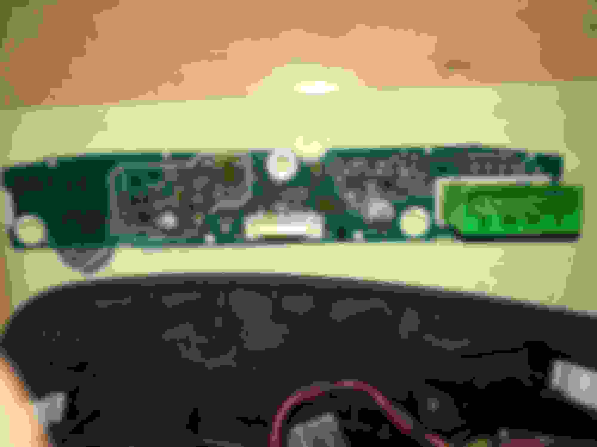
Once open, here's where I am uncertain what is wrong with it. Here's the electronic board:
For the life of me I am unable to see anything wrong with it, also, the previous poster said ending up to simply jamming a piece of rubber under the green connector. there's no image of that, nor any more details.
Can anyone see problems with this board? And what / where to wedge something and close it all backup otherwise?
after unclipping the white casing to open it, to remove the electronic board, you pull out the white square plastic slightly then the connector pulls out once it�s loose.
You then loosen the clips holding the electronic board to the casing and it comes off.
What I think is that there's nothing wrong with the solder job. At least not on mine. It's basically the green connector, the one going into the electronic board (the other connector - the white one - being for the speaker).
I think for whatever reason it becomes loose, and I have a theory. This theory was inspired by a few other owners who in 2005 had their display go blank even when the car was still in it's first year post production.
And while plugging the green connector back in, I have noticed that you could get it in quite the bit, and may easily assume it's a done deal, but the connector could still be pushed further inside. The windshield makes it uncomfortable, and one can easily assume it's plugged properly coz they are doing so at an awkward and tight angle. So, you just press on it more, and it will go in. Even if the unit is installed before the whole dash goes into the car, the connector becomes tight as you plug it in, and you could assume it's plugged, but pushing further there's a little xtra happy ending penetration in there left; pun intended.
This is another manufacturing shortcoming where the assembly process may leave many with slightly loose plugs. Hence why it flickers, dims, and tapping it temporarily helps, etc. Until its further enough through vibration over the years, and it goes blank.
But it's a theory. I'm gonna drive some more and see if it remains on properly. But I tapped on it, and tried a few buttons, went into some pigeon holes; it's steady fully lit. Hopefully that's all it was.
And a little something more: how many went into their stealerships and were told the display unit had to be changed? Price? 5466-766 USD for the unit. It's a 1000 USD dollar job surely, for something requiring 15 minutes to swap, and a piece costing no more than 20 bucks in today's world...
Some when some on here tell you stuff like: did you check with the dealer, did you buy OEM parts, you can safely show them the middle finger.
It may be hard to tell which solder points are bad. While my rubber piece jammed above the green connector did work for a while, I eventually got tired of tapping/hitting it to come back on, I had a tech friend of mine reflow the solder on most of the points and especially the ones under the green connector. Took about 15 mins and zero issues ever since.
Ok, i have noticed that if i just touch the plastic, the actual glass-looking display, that illuminates, and press it upwards, lights go on steady. So, i'm just gonna find something to shove underneath it.
Trust, that gets old fast. You will have to keep hitting\pressing eventually. Its simple to have the solder reflowed. Had mine done a while back and zero issues/taps/hits/presses.
Trust, that gets old fast. You will have to keep hitting\pressing eventually. Its simple to have the solder reflowed. Had mine done a while back and zero issues/taps/hits/presses.
It seems you already went thru all this? hehe
oh well, I'll have to do it soon then. That display started dropping down a bit. I wonder what just went loose.
That area on the dash gets hit with a lot of sun. I think the heating/cooling of that area, the vibration of a car in motion combined with poor soldering is what causes the solder joints to fail.
Great write up. I followed this post and a youtube video to fix the display. It has stayed lit for several hundred miles. Such an easy fix, just touch the ten existing solders on the green connector with a solder iron until it melts. Didn't need to add new solder.
I wish if people, and new users, can search and post in the same thread so as we have a continuity and one size fits all kinda thing.
Ok, so didn't do it at a store, I warmed up the solder for 15 mins, then really just placed the tip on the solders below the green plug. Each at a time, and try and make it melt without crushing it down and splattering it's parts around. Meaning, don't press hard or force it, just heat it up and let it cool, on each head separately.
I did that. and I felt stupid coz if it works..... i should've done it 2 yrs back
I installed it, and again felt like i wanna break the windshield, and almost tore my shoulder muscle, then took a ride. It's on and stable. I'll report back on this in a few weeks if all stays good.
Atta boy! Told you it was maad easy. You will glance at it all the time for a few drives expecting it to be blank or flickering and be so happy to see that its not....Congrats!
Atta boy! Told you it was maad easy. You will glance at it all the time for a few drives expecting it to be blank or flickering and be so happy to see that its not....Congrats!
There's something I entirely forgot to mention yesterday that may be relevant.
I looked accidentally inside the green plug. And it has yellow color metal pins that go inside the connector once you reconnect it.
On of those pins was tilted inside the connector to one side. It wasn't standing straight like the others.
I wedged a large philips screwdriver inside the connector, with the groove of the philips sliding around that pin, and as you push the philips down gently, it's straightening out that pin.
In case it contributed to the problem, take a look inside the green connector.
 04-29-2017, 11:22 PM