Yungone501's- Excessive infatuation with the J-series
 01-03-2013, 08:39 AM
#41
All motor
You repinned the 04 harness with the 07-08 TL-s ECU? 
 01-03-2013, 04:10 PM
#42
Yeah I did. All connectors are the same (ECM sub-harness) and on the engine harness side of the sub harness, all but two circuits are the exact same in regards to pin position as well as color. Now the ECM side of the sub harness is a completely different story and I was required to repin about almost half of the connectors...some circuits changed colors as well which only added to the dilemma! Lol
As far as I could tell, from 04-08 the sub harnesses are the same. Starting in 07, the switched the "A" and "E" connectors around at the ECM.
As far as I could tell, from 04-08 the sub harnesses are the same. Starting in 07, the switched the "A" and "E" connectors around at the ECM.
The following users liked this post:
Sonnick (01-15-2013)
01-04-2013, 06:25 AM
#43
Senior Moderator
Yeah I did. All connectors are the same (ECM sub-harness) and on the engine harness side of the sub harness, all but two circuits are the exact same in regards to pin position as well as color. Now the ECM side of the sub harness is a completely different story and I was required to repin about almost half of the connectors...some circuits changed colors as well which only added to the dilemma! Lol
As far as I could tell, from 04-08 the sub harnesses are the same. Starting in 07, the switched the "A" and "E" connectors around at the ECM.
As far as I could tell, from 04-08 the sub harnesses are the same. Starting in 07, the switched the "A" and "E" connectors around at the ECM.

The following users liked this post:
Sonnick (01-04-2013)
01-04-2013, 08:21 AM
#46
There's no doubt that the harness will work. Those who are interested would need to be advised that C171 on the sub harness will need to be cut out completely and the 17 circuits or so that originally housed will now need to be hard wired. This obviously would require some electrical work to be performed by the person regardless due to having to remove the female and male (male is on the dash harness) sides of C171. As mentioned earlier, most circuits can be matched color for color so the originality almost remains the same...which will def help if repairs or diagnostics are to be done. Anyone who has ever attempted to repair a wiring harness that has un/mis matched color coordination KNOWS what I'm saying here.
Bottom line: the ECM sub harness conversion is a definite thing.
As for more updates: still waiting on the machined portion of the motor mount to come through from my buddy. Should have it in my hand today while at work. Ordered the half shaft bearing and seal from Honda yesterday because NOBODY carries nor can get that bearing size by any means unless from Honda themselves (FACT). My cost was only $38 for both so no big deal.
Once motor is secured in its CORRECT position, I'll then proceed to assembling the exhaust, wiring, cooling system. That should be fairly easy stuff. I also have to convert a few things in the steering column to accept the 07 TL-S lock cylinder and ignition switch and maybe even wire in the 07 TL-S cluster so I can have operable gauges...very important for the first few hours of this engines life!
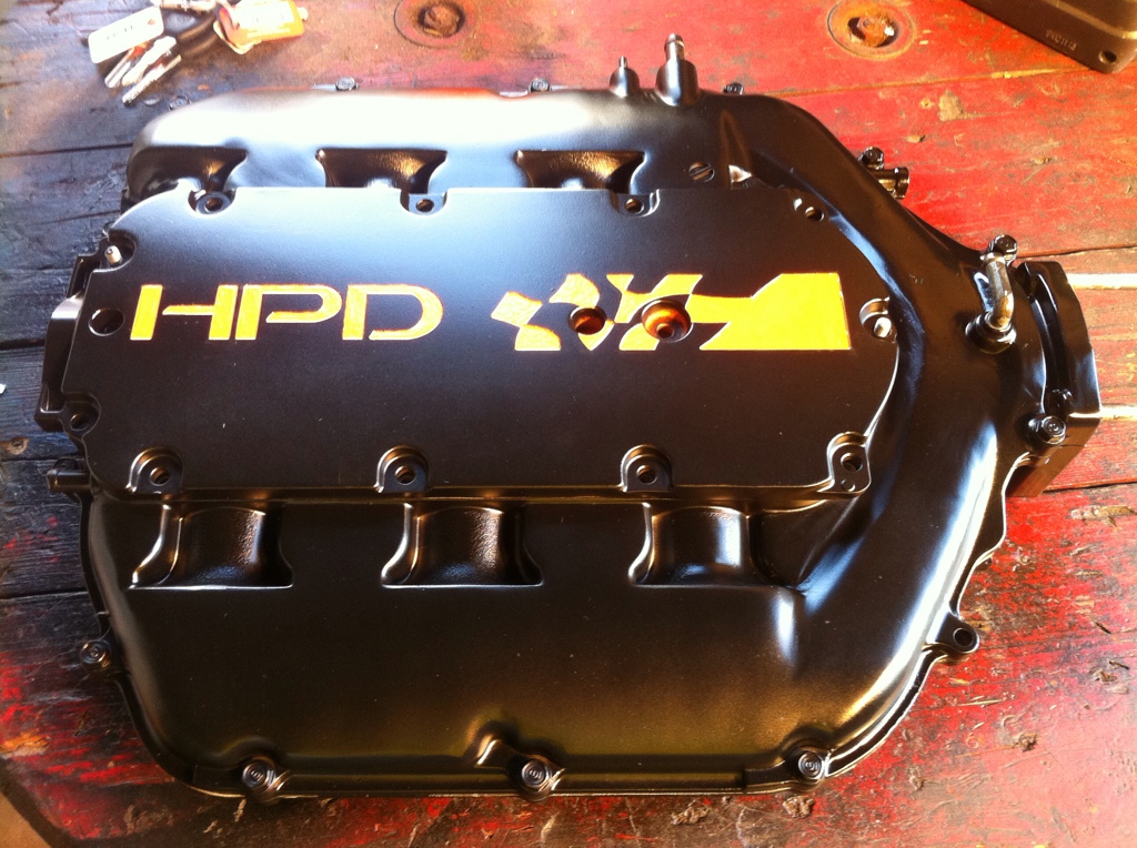
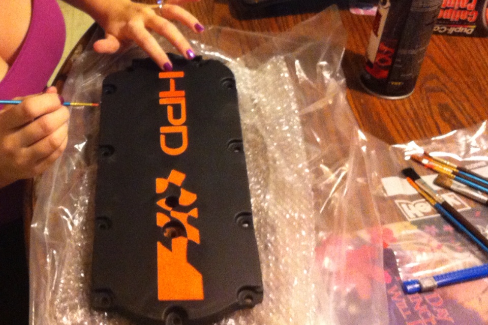
The manifold that I've been working on will finally be receiving its clear coat today and will be finished then installed. Really excited about this one, mmm....

Bottom line: the ECM sub harness conversion is a definite thing.
As for more updates: still waiting on the machined portion of the motor mount to come through from my buddy. Should have it in my hand today while at work. Ordered the half shaft bearing and seal from Honda yesterday because NOBODY carries nor can get that bearing size by any means unless from Honda themselves (FACT). My cost was only $38 for both so no big deal.
Once motor is secured in its CORRECT position, I'll then proceed to assembling the exhaust, wiring, cooling system. That should be fairly easy stuff. I also have to convert a few things in the steering column to accept the 07 TL-S lock cylinder and ignition switch and maybe even wire in the 07 TL-S cluster so I can have operable gauges...very important for the first few hours of this engines life!
The manifold that I've been working on will finally be receiving its clear coat today and will be finished then installed. Really excited about this one, mmm....
The following users liked this post:
Sonnick (01-04-2013)
 01-04-2013, 09:50 PM
#50
Boobs!! Would say a 34 or 36 C...
Looks like you got her a nice ring there. Also apologize forfirst line of this post
Looks like you got her a nice ring there. Also apologize forfirst line of this post
The following users liked this post:
they called me a madman (02-24-2022)

The following 3 users liked this post by yungone501:
01-05-2013, 01:00 AM
#52
The following 4 users liked this post by yungone501:
01-09-2013, 01:05 PM
#54
All motor
yungone501 = boss
01-09-2013, 02:17 PM
#55
takin care of Business in
iTrader: (5)
Join Date: Jan 2008
Location: Kansas City, MO
Age: 40
Posts: 30,994
Received 4,732 Likes
on
4,064 Posts

damn that is SICK SICK SICK !!!
and cant end the comment without mentioning to boobies....you are a lucky man

The following users liked this post:
richardparker (01-09-2013)
01-09-2013, 11:02 PM
#58
Thanks for all the compliments on the car...and my wifes boobs. 
Not really sure yet about this one. All I know is that actual dash fab/modding WILL be required and that's an area that's too well known to me. The cluster over extends the original pod by a 1/2" on both sides. It's doable but just going to have to get creative and crafty.
So, I suppose its about time for an update with words rather than pictures so that I can explain some procedure and detail.
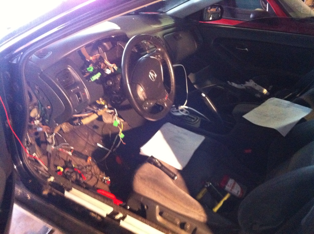
For the past week, I've been working on the harnesses involved until 1:00-2:00am every single night! It's been fun but I have to admit, you start getting to a point where you feel like the work you're doing is so damn repetitive but I kept reminding myself of how the final product would be and I'd be good for another...5 minutes. I basically created several sub-harnesses that included the connector(s) and the harness itself that was made to an estimated length from 'A to B' and I must admit it worked out quite well. I'd say about 80% of all the wiring was done outside of the car which helped considerably. Then, after they were installed (still in this step) they were cut to the required length starting from the component to the destination. All terminals/splices were crimped using uninsulated butt connectors, soldered, heat shrinked, loomed, and then wrapped in electrical tape in critical areas. No make shift or shoddy made connectors were made or used. I used ALL oem connectors and simply repinned to the appropriate terminal positioning and all harnesses even complied to the original diagram coloring. I did this solely for diagnostics in the future if anything ever happened. Those who have attempted to diagnose a harness that was mismatched from a diagram or simply couldn't use a diagram knows what I mean here....F THAT!
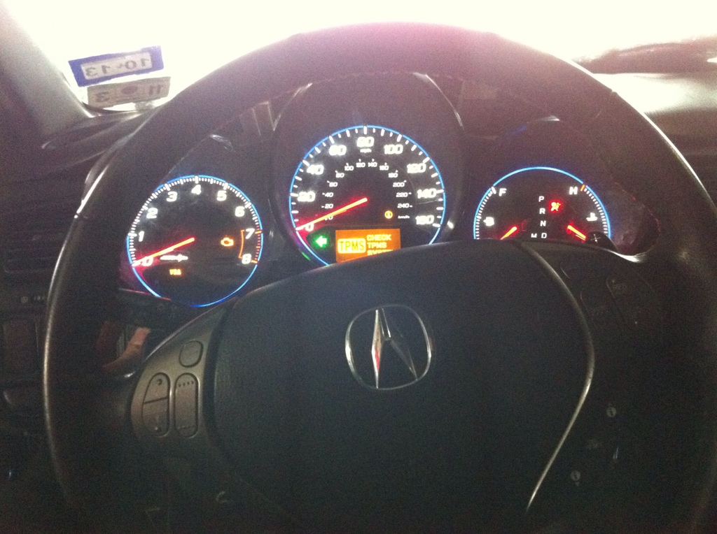
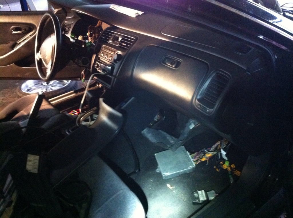
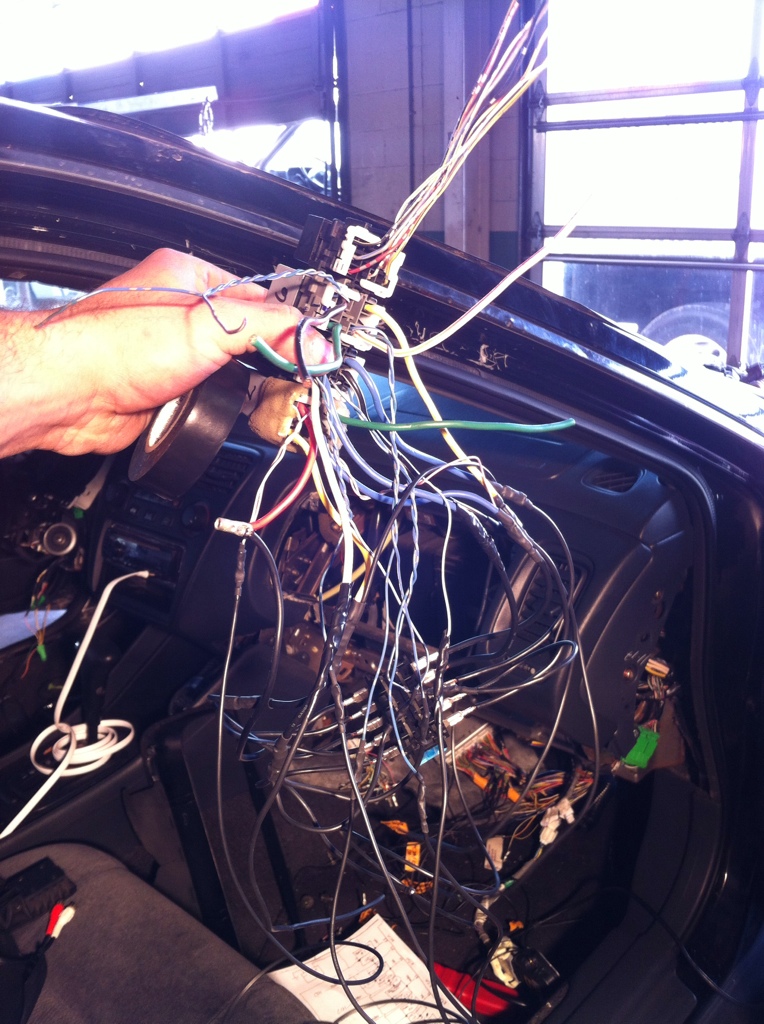
So far, the engine harness is completed. Almost finished with the engine/ECM sub harness...still have connector E on the ECM to go through. Connector E is a totally separate entity from the other four ECM connectors in a sense of actually not physically going to anything on the engine/trans at all. This connector is for CAN comm lines, programming/diagnostic comm lines, ALL powertrain relays, gauges and cluster, immobilizer, etc... I've also got the fuel pump/fuel pump control (FPC) module and harness installed. And yes, the cluster is registering the 2007 TL-S fuel level sensor CORRECTLY. The FPC module is controlled by two small data lines that use something called pulse width modulation (PWM) of which instead of constantly supplying a voltage to the fuel pump at times when high fuel pressure is not required, at idle it can actually decrease fuel pressure down to 15-20psi and essentially allows the vehicle to be more efficient. Cool stuff. In the pictures (that are below) I'm finishing up the immobilizer wiring in the lock cylinder as well as the data link connector (DLC) and was finally able to establish communication from both the instrument cluster and the ECM. It's alive!!!
Here in the next few days, I'm going to wrap up ECM connector E which will require me to build some sort of integrated relay module for all the necessary powertrain relays (PGM-FI 1/2, fuel pump, DBW module, etc...) because the Accord uses a main PGM-FI relay which acts as all of those relays in one. This would cause a MIL to come on due to the ECM not detecting resistance/voltage feedback from the coil of each one of those individual relays. An integrated relay module is a big fancy word for a box that houses relays but greatly simplifies the process of wiring multiple relays by integrating them onto a PCB (printed circuit board) so that all I have to do is add powers/grounds/inputs/outputs and that's cake!!
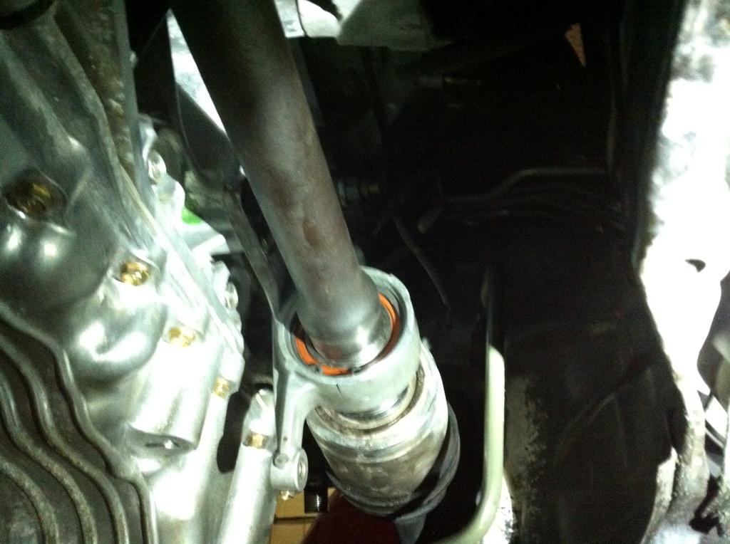
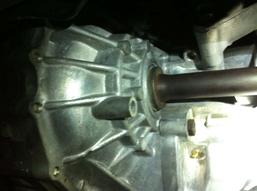
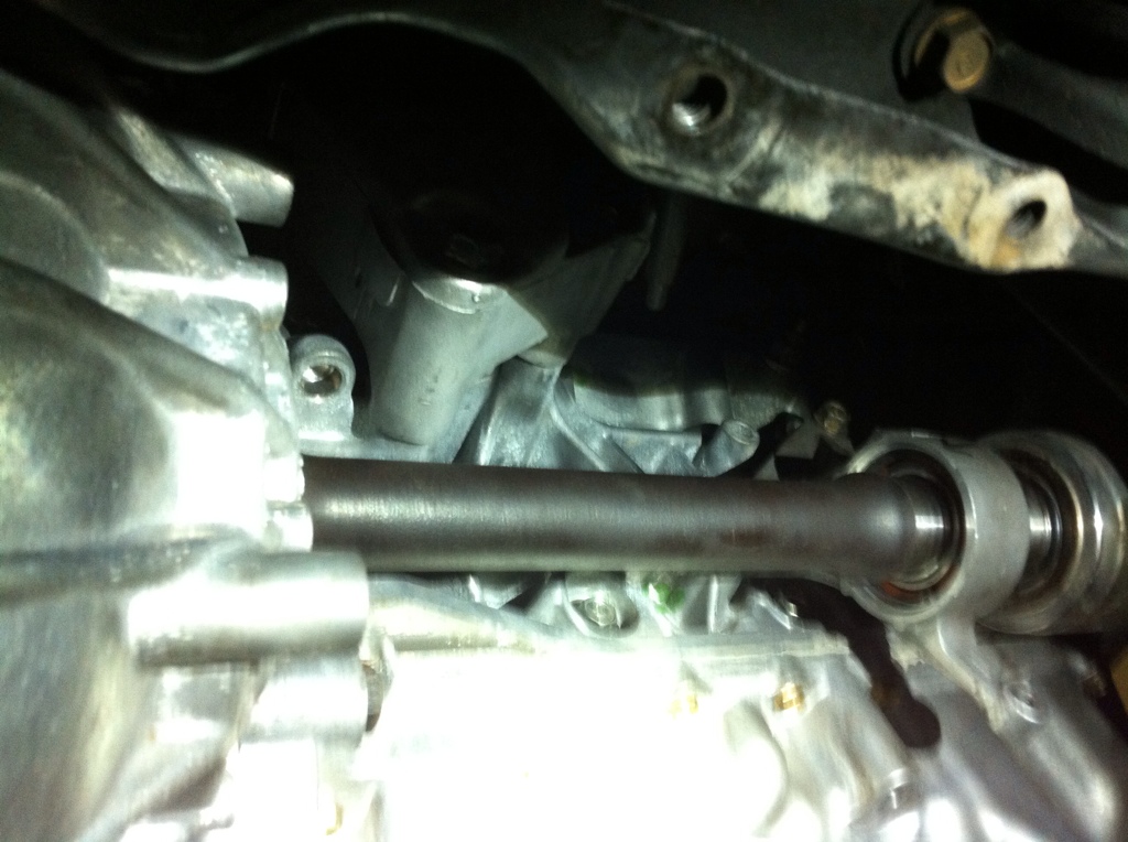
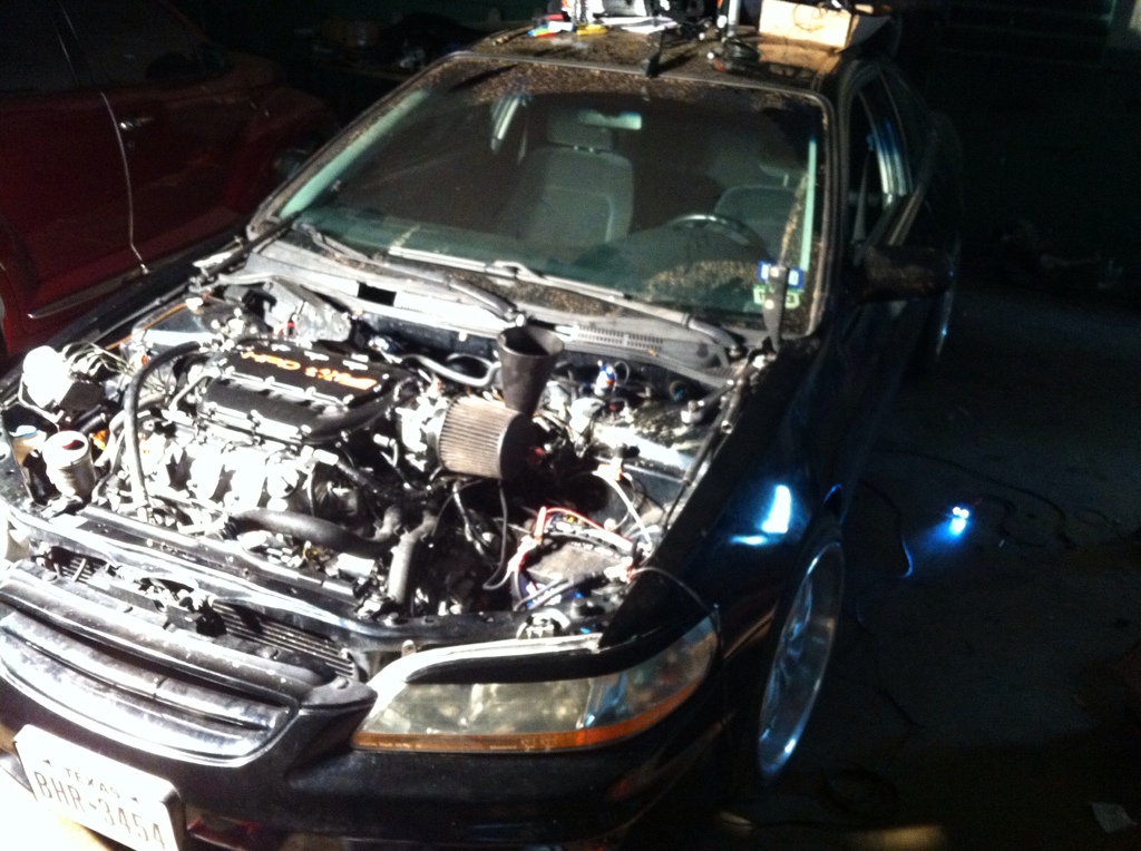
I also still have minor work to do in the engine compartment such as installing that damn troublesome half-shaft that was HEAVILY modified (exaggeration from the issues encountered) but now that's complete. After that its a 30 min job of reinstalling the CV axles and reassembling the steering/suspension and of course the wheels. Also, have to reinstall that beauty of an intake manifold, radiator, alternator, AC compressor, serpentine belt system, catalytic converters, j-pipe, add fluids and then hit the road for a test drive.
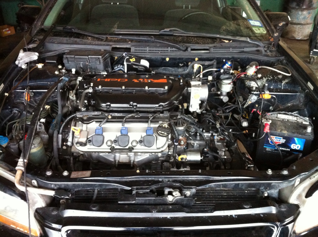
My ultimate overall goal here was to not only install a j35a8 into this 98 Accord, but to do it WITHOUT A MIL LIGHT! All I ever here is how it's expected or acceptable to have a check engine light on with a DBW j motor...I guess this will be the first one without because I know for a fact this one wont. And yes, I'm also including the notorious EVAP system fault into that claim as well. I want to be able to plug this into a state inspection OBD port when my inspection is due and pass without throwing a big tip to the inspector. :-)
I'll say one more thing before closing tonight: for those who are wanting to do a swap like this and make it look good, perform properly and most of all, be done right, expect to either spend a lot of time doing this or pay someone a lot of money for their time. For those who do it themselves, try not to overindulge in the fun you will have. But definitely enjoy yourself. Till next time!!!
Not really sure yet about this one. All I know is that actual dash fab/modding WILL be required and that's an area that's too well known to me. The cluster over extends the original pod by a 1/2" on both sides. It's doable but just going to have to get creative and crafty.
So, I suppose its about time for an update with words rather than pictures so that I can explain some procedure and detail.
For the past week, I've been working on the harnesses involved until 1:00-2:00am every single night! It's been fun but I have to admit, you start getting to a point where you feel like the work you're doing is so damn repetitive but I kept reminding myself of how the final product would be and I'd be good for another...5 minutes. I basically created several sub-harnesses that included the connector(s) and the harness itself that was made to an estimated length from 'A to B' and I must admit it worked out quite well. I'd say about 80% of all the wiring was done outside of the car which helped considerably. Then, after they were installed (still in this step) they were cut to the required length starting from the component to the destination. All terminals/splices were crimped using uninsulated butt connectors, soldered, heat shrinked, loomed, and then wrapped in electrical tape in critical areas. No make shift or shoddy made connectors were made or used. I used ALL oem connectors and simply repinned to the appropriate terminal positioning and all harnesses even complied to the original diagram coloring. I did this solely for diagnostics in the future if anything ever happened. Those who have attempted to diagnose a harness that was mismatched from a diagram or simply couldn't use a diagram knows what I mean here....F THAT!
So far, the engine harness is completed. Almost finished with the engine/ECM sub harness...still have connector E on the ECM to go through. Connector E is a totally separate entity from the other four ECM connectors in a sense of actually not physically going to anything on the engine/trans at all. This connector is for CAN comm lines, programming/diagnostic comm lines, ALL powertrain relays, gauges and cluster, immobilizer, etc... I've also got the fuel pump/fuel pump control (FPC) module and harness installed. And yes, the cluster is registering the 2007 TL-S fuel level sensor CORRECTLY. The FPC module is controlled by two small data lines that use something called pulse width modulation (PWM) of which instead of constantly supplying a voltage to the fuel pump at times when high fuel pressure is not required, at idle it can actually decrease fuel pressure down to 15-20psi and essentially allows the vehicle to be more efficient. Cool stuff. In the pictures (that are below) I'm finishing up the immobilizer wiring in the lock cylinder as well as the data link connector (DLC) and was finally able to establish communication from both the instrument cluster and the ECM. It's alive!!!
Here in the next few days, I'm going to wrap up ECM connector E which will require me to build some sort of integrated relay module for all the necessary powertrain relays (PGM-FI 1/2, fuel pump, DBW module, etc...) because the Accord uses a main PGM-FI relay which acts as all of those relays in one. This would cause a MIL to come on due to the ECM not detecting resistance/voltage feedback from the coil of each one of those individual relays. An integrated relay module is a big fancy word for a box that houses relays but greatly simplifies the process of wiring multiple relays by integrating them onto a PCB (printed circuit board) so that all I have to do is add powers/grounds/inputs/outputs and that's cake!!
I also still have minor work to do in the engine compartment such as installing that damn troublesome half-shaft that was HEAVILY modified (exaggeration from the issues encountered) but now that's complete. After that its a 30 min job of reinstalling the CV axles and reassembling the steering/suspension and of course the wheels. Also, have to reinstall that beauty of an intake manifold, radiator, alternator, AC compressor, serpentine belt system, catalytic converters, j-pipe, add fluids and then hit the road for a test drive.
My ultimate overall goal here was to not only install a j35a8 into this 98 Accord, but to do it WITHOUT A MIL LIGHT! All I ever here is how it's expected or acceptable to have a check engine light on with a DBW j motor...I guess this will be the first one without because I know for a fact this one wont. And yes, I'm also including the notorious EVAP system fault into that claim as well. I want to be able to plug this into a state inspection OBD port when my inspection is due and pass without throwing a big tip to the inspector. :-)
I'll say one more thing before closing tonight: for those who are wanting to do a swap like this and make it look good, perform properly and most of all, be done right, expect to either spend a lot of time doing this or pay someone a lot of money for their time. For those who do it themselves, try not to overindulge in the fun you will have. But definitely enjoy yourself. Till next time!!!
The following users liked this post:
richardparker (01-10-2013)
01-10-2013, 02:08 AM
#59
takin care of Business in
iTrader: (5)
Join Date: Jan 2008
Location: Kansas City, MO
Age: 40
Posts: 30,994
Received 4,732 Likes
on
4,064 Posts
fuq !!!
that is awesome !!!
that is awesome !!!
01-10-2013, 05:00 AM
#60
just crazy!!!! love it.
01-10-2013, 08:30 AM
#61
Senior Moderator
 getting ready to eat the competition and I am cool with that
01-10-2013, 11:46 AM
getting ready to eat the competition and I am cool with that
01-10-2013, 11:46 AM
#64
A few camshafts are useless in a gold plated motor. That is unless the camshafts have been plated as well...then your unquestionably the fastest NA motor ever!
^^^
Words of wisdom for all you gold haters out there...may gold dominate forevermore.
^^^
Words of wisdom for all you gold haters out there...may gold dominate forevermore.
01-10-2013, 01:01 PM
#65
Young might give comp but is car his what 2-300lbs less than mine stock.I don't want to funk up his thread with bs and want to see this project be all it can be.
I want mine the fastest cl,not the fastest car.
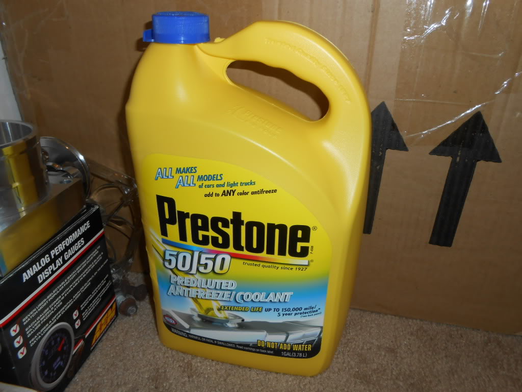
Just came back from the store.
My new mod after I get to the track. Yup the yellow bottle
Last edited by richardparker; 01-10-2013 at 01:04 PM.
 01-10-2013, 11:10 PM
#67
takin care of Business in
iTrader: (5)
Join Date: Jan 2008
Location: Kansas City, MO
Age: 40
Posts: 30,994
Received 4,732 Likes
on
4,064 Posts
you are a motherfawking genius !!!
01-11-2013, 06:56 AM
#68
Senior Moderator
Very nice.
01-11-2013, 08:31 AM
#69
Firstly, I wasn't aware there were 3 ways to spell the word f*ck. Nice!
Next, I've redecided on the integrated relay module for the powertrain electronics. Mainly because I realized I had all the OEM factory relays that I would need that were conveniently attached to the 07 TL-S dash harness I literally had to buy for one, yes ONE, ECM connector. I'm extremely picky with the relays I use for anything I do due to them really needing to be reliable and how there are so many CHEAP relays out there. So, I ended up with four 30A relays and four 20A relays. That's a relay for the following system:
1. PGM-FI 1
2. PGM-FI 2
3. A/F SENSOR
4. DBW MODULE
5. IGNITION
6. RADIATOR FAN
7. CONDENSER FAN
8. A/C COMPRESSOR CLUTCH
I suppose I could've used some of the existing relays/power distribution sources that were already in the car but I didn't feel very good about relying on 15 year old stuff and I wanted all the relays to be purposes for the powertrain electronics. If I had gone the integration relay way, that would've actually been the next easiest route as I would've just soldered in 30A relays all the way and installed the appropriate breaker into the circuit.
I created a diagram/layout sheet for the relays and hopefully will have them in by the end of today. We'll so how work goes at the shop today though.
 01-11-2013, 11:15 AM
#70
Senior Moderator
Regional Coordinator
(Mid-Atlantic)
Regional Coordinator
(Mid-Atlantic)
iTrader: (6)
Such a great build, I love seeing it come along. Nice work
01-12-2013, 08:28 PM
#71
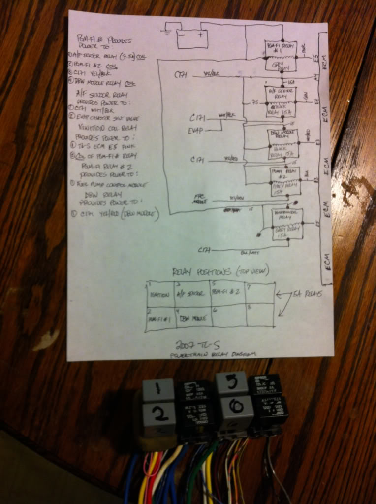
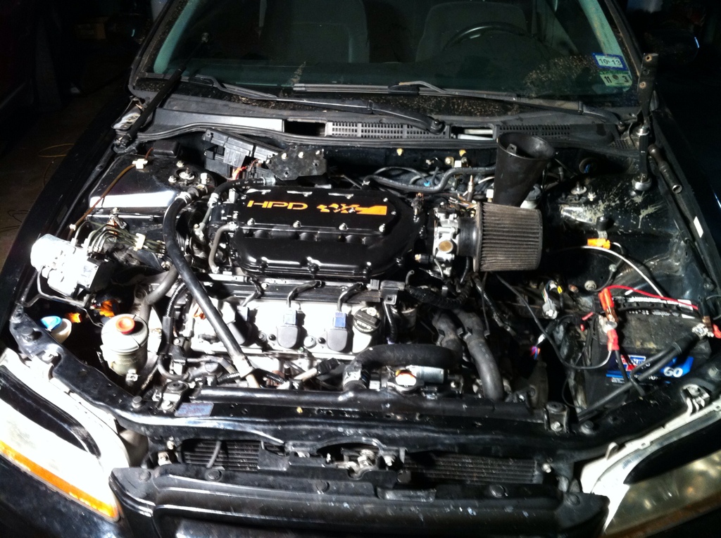
Almost have the wiring completed enough to have a first start. I've managed to gain access with the ECM but have been confronted with a CAN issue which was disrupting the programming process. It's all good though, this is what makes it fun and challenging...trial and error. Took a few shots of the wiring process and harness install. Here they are:
PGM-FI relay setup before its integration into the j35a8 wiring harness.
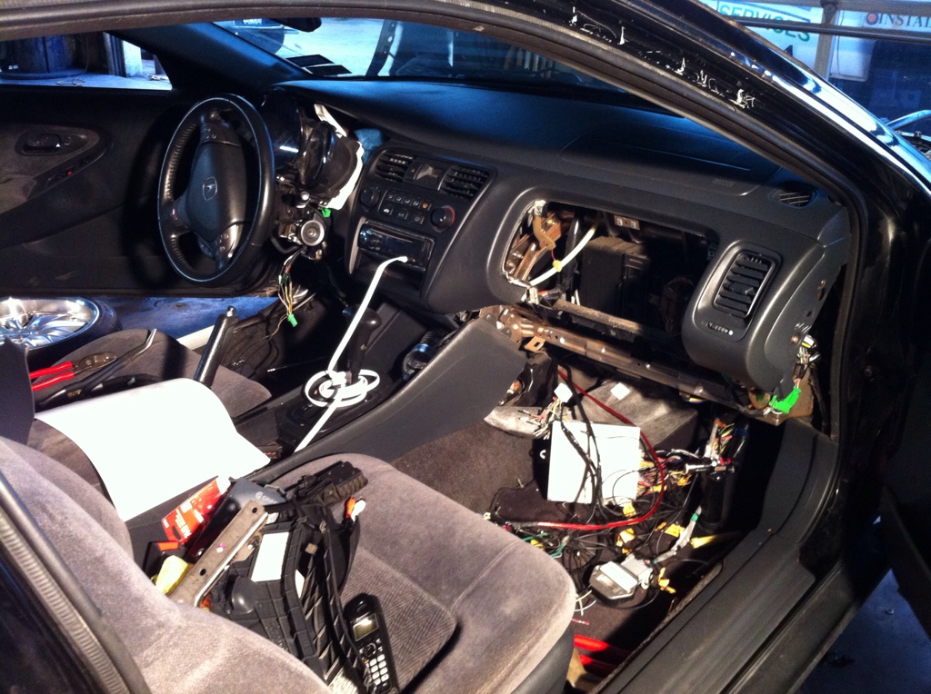
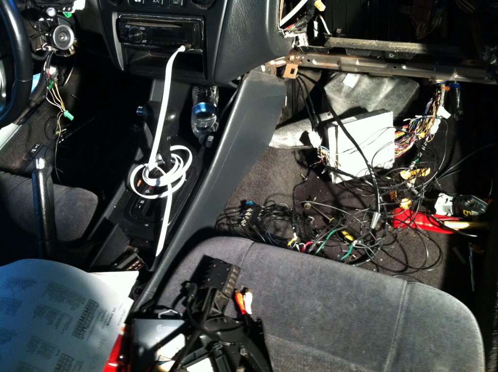
And then some from tonight after finally getting the car down on the ground...
PGM-FI relay setup before its integration into the j35a8 wiring harness.
And then some from tonight after finally getting the car down on the ground...
 01-13-2013, 07:56 PM
#73
 01-13-2013, 09:06 PM
#74
wow quite the project, talk about spaghetti! im from 6thgenaccord.com and i didnt expect to see a swap in an accord on here, you know the 2001-2003 cl or tl near that generations dash fits in the accord? http://www.6thgenaccord.com/forums/s...highlight=dash heres a thread on the cg2 swap. what're you doing about hood clearance?
01-14-2013, 12:27 AM
#75
wow quite the project, talk about spaghetti! im from 6thgenaccord.com and i didnt expect to see a swap in an accord on here, you know the 2001-2003 cl or tl near that generations dash fits in the accord? http://www.6thgenaccord.com/forums/s...highlight=dash heres a thread on the cg2 swap. what're you doing about hood clearance?
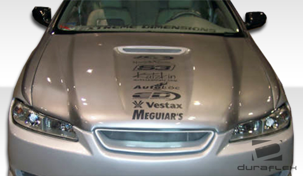
One step at a time here, gotta get this motor running first. Get too excited talking about this stuff! ;-)
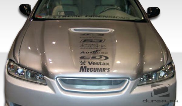
For hood clearance, thinking something like this:
 01-14-2013, 03:40 PM
#77
takin care of Business in
iTrader: (5)
Join Date: Jan 2008
Location: Kansas City, MO
Age: 40
Posts: 30,994
Received 4,732 Likes
on
4,064 Posts
ohh there are a lot many more ways to spell the good ol' "fuck" 
that is an amazing build !!!
that is an amazing build !!!
01-14-2013, 05:43 PM
#78