
Trans temp gauge ?


 07-19-2014, 10:52 PM
#3
07-19-2014, 11:29 PM
#4
I've been monitoring ATF temp a few ways.
From the OBD2 port via a Honda clone and Software. I've had a Car computer and 8" Touch screen, sunlight readable LCD installed for 4 or 5 years now.
I've been plotting ATF temps V Coolant temps over time with:
1. OEM Warmer/cooler only.
2. Warmer/cooler in series with big front mounted ATF cooler.
3. As above but with a temp bypass valve for the front cooler.
4. Just the front cooler and temp bypass. (OEM warmer removed)
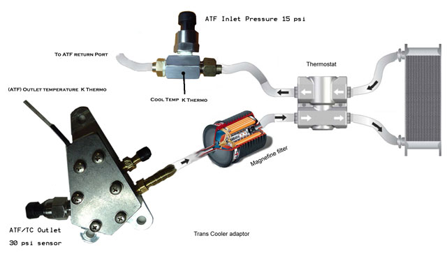
Recently tested using the Inlet line at the back of the trans with a K-thermocouple - around $15 to $20.
I'm in the process of fitting a low cost ($25) 0-30 PSI electronic fluid pressure sensor with a K-thermocouple attached to the aluminium inline adaptor.
I've just replaced the OEM Warmer/cooler (my 5AT has one on top) with an adaptor to plumb ATF fluid directly to the Huge front mounted ATF Plate cooler, had it on for years, via a temperature bypass valve.
As a result I will be mounting another K-thermocouple to the outlet hose as Torque convertor overheating is a problem, especially with the earlier 5AT transmissions as they age. I want to keep an eye on TC output temperatures along with (I hope) Cooler line pressure.
I can post pictures of the adaptor (available on eBay) modified for my small electronic pressure sensor, was originally used as an adaptor for a ATF fan temperature switch.
FYI the Pressure sensor has to be interfaced to a Microcontroller, the K-thermocouple can be purchased with a multimeter type gauge, however there is a small adaptor available that outputs a voltage proportional to the temperature, once again best interfaced to a small microprocessor (if you want a mountable gauge or display).
I've also programmed a $20 micro to drive a small $15 2 line LCD display that shows temperature and pressure. Only 4 or 5 components and easy to build.
I you're interested, I'll post pictures when it's fitted, some time this week.
There are of course a few other temperature sensors available that aren't focused on a Thermocouple. Apart from some crude large sensors more suited to coolant temperature fitting most small accurate units appear to need some kind of electronic interface.
From the OBD2 port via a Honda clone and Software. I've had a Car computer and 8" Touch screen, sunlight readable LCD installed for 4 or 5 years now.
I've been plotting ATF temps V Coolant temps over time with:
1. OEM Warmer/cooler only.
2. Warmer/cooler in series with big front mounted ATF cooler.
3. As above but with a temp bypass valve for the front cooler.
4. Just the front cooler and temp bypass. (OEM warmer removed)
Recently tested using the Inlet line at the back of the trans with a K-thermocouple - around $15 to $20.
I'm in the process of fitting a low cost ($25) 0-30 PSI electronic fluid pressure sensor with a K-thermocouple attached to the aluminium inline adaptor.
I've just replaced the OEM Warmer/cooler (my 5AT has one on top) with an adaptor to plumb ATF fluid directly to the Huge front mounted ATF Plate cooler, had it on for years, via a temperature bypass valve.
As a result I will be mounting another K-thermocouple to the outlet hose as Torque convertor overheating is a problem, especially with the earlier 5AT transmissions as they age. I want to keep an eye on TC output temperatures along with (I hope) Cooler line pressure.
I can post pictures of the adaptor (available on eBay) modified for my small electronic pressure sensor, was originally used as an adaptor for a ATF fan temperature switch.
FYI the Pressure sensor has to be interfaced to a Microcontroller, the K-thermocouple can be purchased with a multimeter type gauge, however there is a small adaptor available that outputs a voltage proportional to the temperature, once again best interfaced to a small microprocessor (if you want a mountable gauge or display).
I've also programmed a $20 micro to drive a small $15 2 line LCD display that shows temperature and pressure. Only 4 or 5 components and easy to build.
I you're interested, I'll post pictures when it's fitted, some time this week.
There are of course a few other temperature sensors available that aren't focused on a Thermocouple. Apart from some crude large sensors more suited to coolant temperature fitting most small accurate units appear to need some kind of electronic interface.
Last edited by Mkarl; 07-19-2014 at 11:32 PM.
07-20-2014, 11:35 AM
#5
I have I a trans cooler and a trans temp gauge on my 01 cls. Made a massive difference... Temps stay bellow 220 no matter what. Before it could get to 280!!! even higher if ur ripping it..
My bro just bought a tl type s and I saw a small trans cooler mounted in the front righ of the car.
On my car I put it directly behind the grill so it gets maximum amount of air passing through it
My bro just bought a tl type s and I saw a small trans cooler mounted in the front righ of the car.
On my car I put it directly behind the grill so it gets maximum amount of air passing through it
07-21-2014, 03:36 AM
#6
For anyone interested: Just fitted the ATF cooler Oil pressure sensor and found a VERY simple way adapt and monitor TC fluid output (trans ATF outlet) with a K- Thermocouple for almost instant indication of temp change.
Started the vehicle to check for leaks (none) and after a few minutes put the Selector into D, ATF temperature immediately started to rise, back to P and it immediately started to drop. Put in 2nd, vehicle braked and increased RPM for a second to 1200 RPM and TC output makes a straight vertical rise on the log graph. These K-thermos are so sensitive and fast that during testing just blowing in the direction of one from 6 feet away caused the temps to spike. I can definitely catch a sudden high TC spike temp now.
Oil Pressure ran at 26 PSI in Park when cold at idle. Down to 15 PSI hot. Lowest reading was 2.1 PSI in gear hot at idle. This is the area that has been identified as one of the causes of unexplained TC overheating failures in the 5AT. In other words flow rate drops below 0.7 GPM or zero in this situation. Don't know what the flow rate is at 2.1 PSI, but it's not 0. The recommendation I have seen is never let flow rate drop below 0.8 GPM @ Hot idle in gear. NOTE: I'm measuring Pressure at the fluid return INLET on the transmission: That's after the filter and cooler and bypass valve.
So far I've not driven the vehicle far as the monitoring setup was just hanging together for a quick test.
Another point of interest is this pressure sensor has electronics and a signal amplifier built into the stainless steel sensor housing, response time is quoted ≤1ms, Accuracy +/-1% FS. Its fast enough to show a momentary spike pressure drop to almost zero as the shift lever is moved between P-D-R etc.
The following 2 users liked this post by Mkarl:
Jboat (07-28-2014),
Timthetoolman (07-21-2014)
07-21-2014, 06:46 AM
#7
-------Tim-------
^Just to let to know, I appreciate all your effort and sharing of info on this subject. It would be great to have a thread regarding all of what you have done, just to have the info in one area. Thanks again, I will be researching a trans cooler to install in my '04. I don't know if I could add all the temp sensors and what not, but it could benefit the community here.
Thanks Again Mkari!
Thanks Again Mkari!
Trending Topics
 07-22-2014, 03:45 AM
#9
^Just to let to know, I appreciate all your effort and sharing of info on this subject. It would be great to have a thread regarding all of what you have done, just to have the info in one area. Thanks again, I will be researching a trans cooler to install in my '04. I don't know if I could add all the temp sensors and what not, but it could benefit the community here. Thanks Again Mkari!
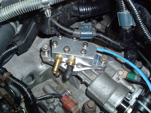
Just finished the under bonnet install: Mounted a sensor connection case and tidied up the 3 sensor cables that now run to it. I've left room for expansion as the cable running back through the firewall is a shielded 6 pair cable, also just finished running that and giving it a quick test to ensure everything works with no interference from the running engine - perfect.
Apart from the TC temp sensor and Pressure sensor, I also have a K-thermo on the outlet side of the cooler (mounted with the Pressure sensor case).
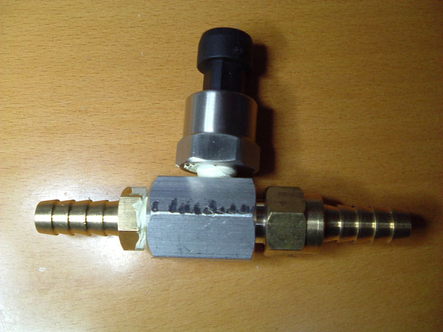
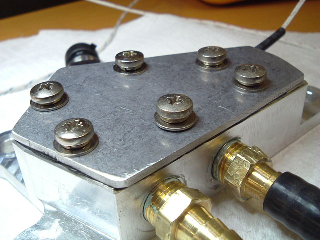
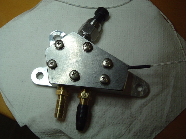
Here is picture of the Pressure sensor and adaptor. NOTE: I had a Hose and connection company Tap the fitting for the P-sensor, not the best job but I didn't have the correct tap to do it myself, anyway it's solid and no leaks, jaw marks are theirs as well. Not shown is a K-thermo mounted to the side of the aluminium housing and covered in aluminium insulating tape.
FYI here is picture of the K-Thermocouple.
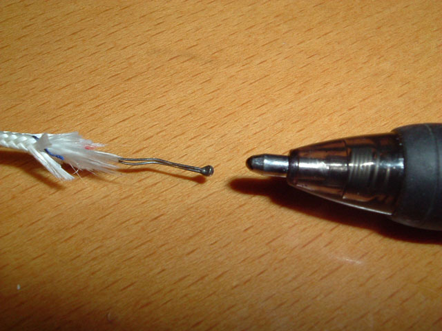
Now for something that will make some people collapse in shock and horror (whatever). Notice how small the sensor head is? I wanted to monitor instantaneous changes (spikes) in TC output so I needed a way to close-couple this sensor to the fluid. I tested my idea @ over 120 psi and it was perfect. I used a tiny Philips head jewellers screw driver to punch a tiny hole in the ATF Cooler hose, before the hose could collapse back I inserted the tip of the K-T into the hose with the head just proud of the inner side of the tube. The sensor and bare connection cable are covered with High temp non-acidic silicon sealer and taped over with a few layers aluminium insulating tape. This tape is "super strong" and very sticky, it has to be cut and hacked off if it ever needs to be removed. The sensor is mounted BEFORE the filter (in case it ever breaks - unlikely). Results are perfect with instant tracking of TC output temp changes, more that I had hoped for.
Last edited by Mkarl; 07-22-2014 at 03:47 AM.
07-23-2014, 10:14 PM
#11
LINK - > Under Transmission The ATF cooler page has not been updated with this ATF cooler line Pressure or TC output installation or measurements as yet.
Just got back from a first run of monitoring and some interesting results to follow - especially Pressure - could not get the temps above 80 C (176 F) even at the TC outlet, which is just below the trip point for the external cooler temperature bypass operation (180F).
Just got back from a first run of monitoring and some interesting results to follow - especially Pressure - could not get the temps above 80 C (176 F) even at the TC outlet, which is just below the trip point for the external cooler temperature bypass operation (180F).
07-23-2014, 10:42 PM
#12
Make sure u put the temp gauge on the beginning before the trans cooler. If u put it after the temp gauge will move around cause it's giving u the temp of the fluid coming out of the cooler.... Not the temp of the fluid in the actual trans
07-23-2014, 10:48 PM
#13
The TC (ATF outlet) is monitored 3" from the TRANS ATF EXIT port and directly IN the FLUID.
The Sensor after the cooler is monitored Via an isolated Pressure sensor housing in the last foot of the ATF return line before ATF return port.
07-25-2014, 01:15 AM
#14
At last I have some data.
Start temp was 20 deg but I had the vehicle idling for 10 minutes while I sorted my home built recording equipment in the vehicle for the first time after loading new software (had only just finished coding).
Anyway, trip was a slow drive of 4 minutes to local Jaycar store, then 5 min drive at 36 mph (in D3) and then around 15 minutes at 50 MPH, back to 10 minutes in traffic (D3) and a few sets of lights.
ATF temps had reached around 60C (140F) after 18 minutes on the graph but I had been stopped for around 5 minutes (no recording for 5 minutes) in reality it had reached 60C (140F) in around 10 minutes as I had some time at the start just idling in P.
Cooler line Pressure is of course almost totally dependent on engine RPM, with an overall pressure drop as the viscosity of ATF thins with heat.
It's interesting that when ATF is above 60c the PSI drops to almost zero in gear at 750 RPM, however as I am measuring this at the outlet of the cooler and almost at the end of the return ATF line it is a bit misleading, but nonetheless indicates that the quoted measured values of around 0.8 GPM warm at Idle in gear is correct.
The classic problem with too little coolant flow internally through the TC is a massive increase in TC temperature followed by a huge spike in TC ATF output temp as RPM's rise enough for ATF to be pushed through the cooler line. I have absolutely NO increase in TC-ATF outlet temperatures. A simple way to test this was to put the vehicle in P or N after idling for a few minutes in gear, the increased RPM causes a PSI increase and my ATF outlet fluid does not rise at all, in fact it starts to drop as the TC is no longer slipping (generating heat) in D when stationary. It means that even though the pressure gauge is showing zero there is in fact sufficient flow rate internally to keep the TC cool and there is still flow through the cooler line. More info on this to come.
Another note is whenever I drove through the gears hard there was an immediate increase in ATF outlet temps caused by the TC, but only a few deg increase, as soon as I backed off, temps dropped.
Pressure is low (at measuring location) when in 5th below 60mph, it only reads around 5 PSI at 50mph in 5th.
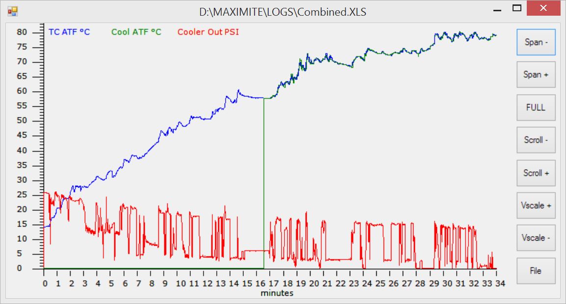
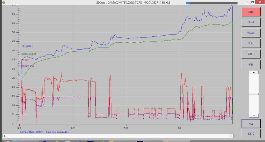
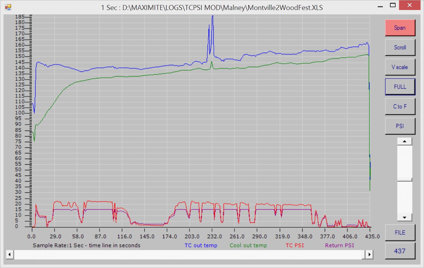
Finally the graph: This is not ideal as it's cramped but it gives an idea, when expanded it's amazing how outlet temps respond so quickly to TC and clutch pack load.
That low PSI towards the end is some testing of ATF outlet temp changes at idle in gear, slow reverse, neutral etc. Didn't have any luck in opening the cooler bypass, looking at he graph, perhaps I had but its hard to tell as the bypass valve keeps the cooler full even in bypass. But previous tests showed it opening/closing and holding the outlet temps at around 83c (around 182F).
I forgot to enable the ATF cooler outlet monitor (green) until about half way through the drive (what can I say). Notice it tracks hot ATF outlet as the cooler bypass is still closed, ATF outlet temps have not reached the bypass opening temperature of 82c.
This is a graph data generated by a tiny MaxiMite microcomputer (around $60), has 20 IO ports (10 ADC 10 Digital) and can drive an LCD directly, has an SD card slot (64GB card installed) to hold the running program and log data, compatible with Windows file system.
Longer test drives in slow traffic and the local mountain range
Start temp was 20 deg but I had the vehicle idling for 10 minutes while I sorted my home built recording equipment in the vehicle for the first time after loading new software (had only just finished coding).
Anyway, trip was a slow drive of 4 minutes to local Jaycar store, then 5 min drive at 36 mph (in D3) and then around 15 minutes at 50 MPH, back to 10 minutes in traffic (D3) and a few sets of lights.
ATF temps had reached around 60C (140F) after 18 minutes on the graph but I had been stopped for around 5 minutes (no recording for 5 minutes) in reality it had reached 60C (140F) in around 10 minutes as I had some time at the start just idling in P.
Cooler line Pressure is of course almost totally dependent on engine RPM, with an overall pressure drop as the viscosity of ATF thins with heat.
It's interesting that when ATF is above 60c the PSI drops to almost zero in gear at 750 RPM, however as I am measuring this at the outlet of the cooler and almost at the end of the return ATF line it is a bit misleading, but nonetheless indicates that the quoted measured values of around 0.8 GPM warm at Idle in gear is correct.
The classic problem with too little coolant flow internally through the TC is a massive increase in TC temperature followed by a huge spike in TC ATF output temp as RPM's rise enough for ATF to be pushed through the cooler line. I have absolutely NO increase in TC-ATF outlet temperatures. A simple way to test this was to put the vehicle in P or N after idling for a few minutes in gear, the increased RPM causes a PSI increase and my ATF outlet fluid does not rise at all, in fact it starts to drop as the TC is no longer slipping (generating heat) in D when stationary. It means that even though the pressure gauge is showing zero there is in fact sufficient flow rate internally to keep the TC cool and there is still flow through the cooler line. More info on this to come.
Another note is whenever I drove through the gears hard there was an immediate increase in ATF outlet temps caused by the TC, but only a few deg increase, as soon as I backed off, temps dropped.
Pressure is low (at measuring location) when in 5th below 60mph, it only reads around 5 PSI at 50mph in 5th.
Finally the graph: This is not ideal as it's cramped but it gives an idea, when expanded it's amazing how outlet temps respond so quickly to TC and clutch pack load.
That low PSI towards the end is some testing of ATF outlet temp changes at idle in gear, slow reverse, neutral etc. Didn't have any luck in opening the cooler bypass, looking at he graph, perhaps I had but its hard to tell as the bypass valve keeps the cooler full even in bypass. But previous tests showed it opening/closing and holding the outlet temps at around 83c (around 182F).
I forgot to enable the ATF cooler outlet monitor (green) until about half way through the drive (what can I say). Notice it tracks hot ATF outlet as the cooler bypass is still closed, ATF outlet temps have not reached the bypass opening temperature of 82c.
This is a graph data generated by a tiny MaxiMite microcomputer (around $60), has 20 IO ports (10 ADC 10 Digital) and can drive an LCD directly, has an SD card slot (64GB card installed) to hold the running program and log data, compatible with Windows file system.
Longer test drives in slow traffic and the local mountain range
Last edited by Mkarl; 07-25-2014 at 01:18 AM.
07-27-2014, 11:05 PM
#15
One thing that happens when you spend time looking and measuring just one area of a vehicle, it causes you to dig a little deeper into the operation and interpretation of measured results or data. Further reading into pressure drop over a fluid line would indicate that pressure will be different towards the end of the line compared to the start. Logic would indicate that measuring close to the outlet where flow is increasing will give the lowest reading - providing the outlet is not restricted - and this is where I'm measuring external cooler pressure.
It's also a logical assumption that as fluid viscosity lowers from heat (thins) there will be less pressure required to flow the same volume of fluid through the line. It follows that any restriction to flow "after the measuring point" will also flow more - hot thin - fluid with less back pressure/resistance to flow.
My feelings after thinking long and hard about the first round of readings (more to come today) is that the PSI readings I'm seeing are more an indication of max pressure (at that measuring location) and not the true outlet pressure generated by and through the TC. I feel from posted info that I'm likely reading around 5 PSI less that directly at the Trans outlet (input of the external cooler line). Yes I could shift the Sensor but there is no room for it at the outlet, and really there is an easier way to tell if I have insufficient flow rate.
Once I establish the normal PSI at this location I will have an indicator of any fault/loss in the future and by adding a low pressure alarm I will know instantly of any ATF hose failure of restriction - before any damage can be done.
Again, it's flow rate that's important in the cooler line, and as the flow rate "HOT in gear" in a newly rebuilt and modified transmission is quoted at only 0.8 GPM then pressure may indicate 0 in this one instance in the location I'm measuring, however flow rate certainly is not low. The proof? That fast response thermocouple I mounted directly in the fluid stream right at the outlet of the TC (ATF trans outlet).
Any loss of flow below 0.8 GPM will cause an immediate massive rise in TC temperature, and will show as fluid outlet temperatures spikes the instant flow restarts/increases with rising RPM (above 1300 RPM). Temperatures from 250F to 360F have been measures at the TC outlet with low or no flow after full flow resumption.
IE: If flow had reduced to the point of causing an already hot (from normal driving) TC to overheat from TC slip while stationary at idle in gear, the temp sensor will show it. Sufficient fluid flow at low pressure is the key, unfortunately quality flow sensors that can run at temps above 90C are dam expensive.
Testing data by transmission people at Sonnax confirmed readings posted by owners showing ATF running at around 205F around town once fully warm and 230F on hot days in traffic. Other tests on a transmission with a replacement TC and mods for Cooler circuit flow (flow at or above 0.8 GPM) still showed ATF temps reaching 235F in traffic on Hot days. Adding a larger external cooler in series with the Radiator tank exchanger held temps down to around 205F to 210F.
QUOTE TC rebuilder:
You may be wondering why 20-25 psi was the sweet spot for testing the Honda converters, rather than the 40 psi that worked on other units. Honda does not use the typical two-path apply and release circuit that is used in the 4R100, 4L60-E, 5R55E, and many other applications Instead, it uses a three path oil circuit that incorporates a converter bypass valve like the circuits found in some front wheel drive Fords; eg. CD4E, AX4N, and AX4S. For this reason the circuit is especially sensitive to outside variables such as restricted coolers and cross leaks. Honda converter charge oil comes from the charge oil circuit of the main regulator valve. With this design, charge pressure is often only half of what line pressure would be. This is why the lockup clutches of the Honda converters need to be tested at 20 to 25 psi instead of the 40 psi that is used on other units.
07-27-2014, 11:06 PM
#16
Just completed a 40 minute drive. A mix of 60kmh (37mph) hilly 80kmh (50mph) and 100kmh (62mph) with sudden drops to 60kmh and stop start traffic.
Outside temperature is not that high at around 25�C (77�F). Temperature of vehicle block at start up in the shed was around 16�C.
About the sensors and the first graph: On the first graph the cooler outlet temperature was not being read correctly, it was showing the TC outlet temperature - wondered why they tracked each other - see below.
These k-thermos need a special input device to allow for junction temperature variations and other parameters. There is a small CHIP available for around $12.00 that only has one or two components and converts the K-Thermo output to a 10mv per deg output. You could read this on a standard $10 multimeter. You can also purchase a small readymade board with screw connectors. Anyway I only had one of these CHIPS when I made the board so for now I just modified my software to remotely switch (almost seamlessly) between the two K-thermo devices.
I wrote the SW to monitor the Cooler outlet sensor once every 5 seconds (when it's enabled), the TC sensor is monitored every second except for that one second reading for the Cooler outlet sensor when it's enabled.
FYI During the one second reading time the Pressure and both ATF sensors are read around 800 times each, the average of the total number of readings is calculated and displayed. I can change the update reading to 80 reads every 100 milliseconds and update graph and meter display every 100ms when needed, however logged data files get large.
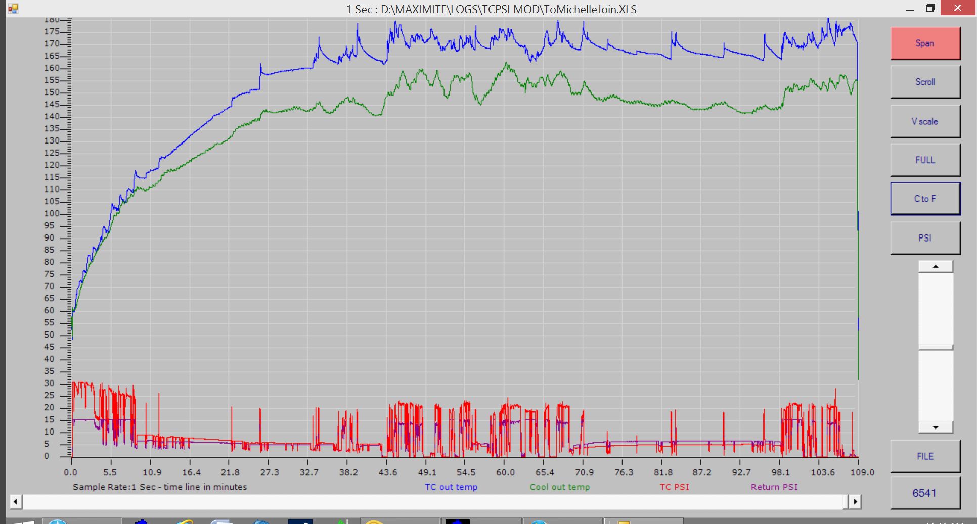
Onto the Graph: Once again compressed into one screen:
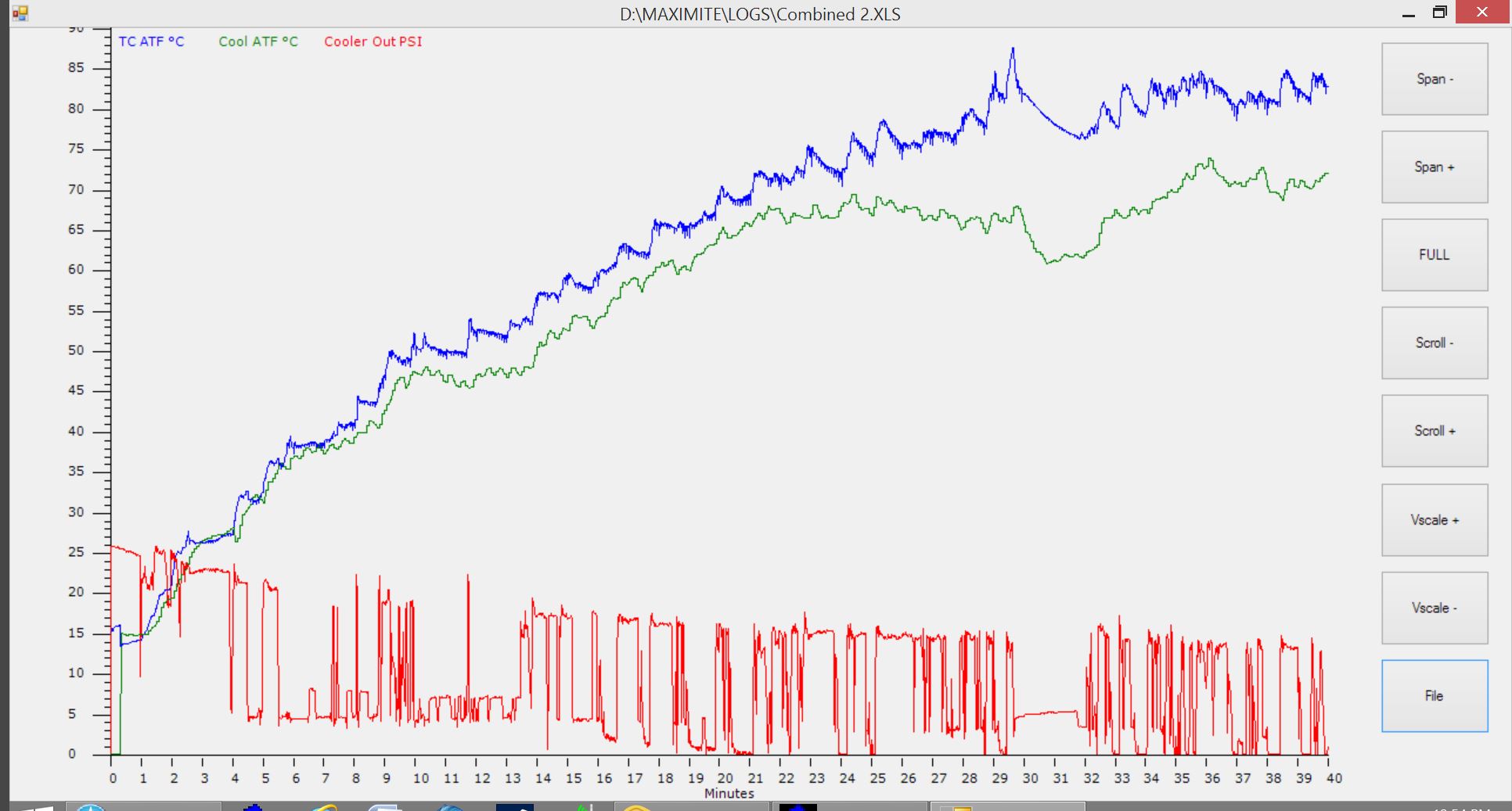
The interesting thing to note is the display from 29 minutes to 32 minutes. I stopped, waited for traffic to clear and accelerated quite quickly to 62mph: So at 29.3 minutes I was stopped and waiting, the sharp rise in PSI at 29.4 is 1st gear, there are 3 dips at the top of the spike for each gear and a sharp drop to 7PSI as it shifted into 5th. You can see an immediate spike in TC temperatures as the acceleration to 62 mph occurred, followed by a quick drop in temperatures between 29.7m and 32 minute marks as it cruised in 5th. Cooler output dropped to 60C quite quickly followed by ATF TC output temperatures (it's a big cooler) following that I dropped quickly to an off ramp and stopped at traffic lights. The remainder of the drive was start stop traffic, despite the fact that I was travelling slowly and stopping quite often, cooler output temps held at around 73�C. No cooler fan but the AC fans were running. Looking forward to Hot summer days to really start testing this out. I'm planning on some long taxing drives before then.
I measured the OEM transmission ATF sensor via OBD2 and it did what I expected:
1: Matched the TC outlet temperature whenever the TC is locked or not slipping much.
2: Always matches TC out when the trans in "N" or "P"
3: Most of the time you could add around 5�C to the "constant range output" of the cooler outlet temp sensor and be close.
Outside temperature is not that high at around 25�C (77�F). Temperature of vehicle block at start up in the shed was around 16�C.
About the sensors and the first graph: On the first graph the cooler outlet temperature was not being read correctly, it was showing the TC outlet temperature - wondered why they tracked each other - see below.
These k-thermos need a special input device to allow for junction temperature variations and other parameters. There is a small CHIP available for around $12.00 that only has one or two components and converts the K-Thermo output to a 10mv per deg output. You could read this on a standard $10 multimeter. You can also purchase a small readymade board with screw connectors. Anyway I only had one of these CHIPS when I made the board so for now I just modified my software to remotely switch (almost seamlessly) between the two K-thermo devices.
I wrote the SW to monitor the Cooler outlet sensor once every 5 seconds (when it's enabled), the TC sensor is monitored every second except for that one second reading for the Cooler outlet sensor when it's enabled.
FYI During the one second reading time the Pressure and both ATF sensors are read around 800 times each, the average of the total number of readings is calculated and displayed. I can change the update reading to 80 reads every 100 milliseconds and update graph and meter display every 100ms when needed, however logged data files get large.
Onto the Graph: Once again compressed into one screen:
The interesting thing to note is the display from 29 minutes to 32 minutes. I stopped, waited for traffic to clear and accelerated quite quickly to 62mph: So at 29.3 minutes I was stopped and waiting, the sharp rise in PSI at 29.4 is 1st gear, there are 3 dips at the top of the spike for each gear and a sharp drop to 7PSI as it shifted into 5th. You can see an immediate spike in TC temperatures as the acceleration to 62 mph occurred, followed by a quick drop in temperatures between 29.7m and 32 minute marks as it cruised in 5th. Cooler output dropped to 60C quite quickly followed by ATF TC output temperatures (it's a big cooler) following that I dropped quickly to an off ramp and stopped at traffic lights. The remainder of the drive was start stop traffic, despite the fact that I was travelling slowly and stopping quite often, cooler output temps held at around 73�C. No cooler fan but the AC fans were running. Looking forward to Hot summer days to really start testing this out. I'm planning on some long taxing drives before then.
I measured the OEM transmission ATF sensor via OBD2 and it did what I expected:
1: Matched the TC outlet temperature whenever the TC is locked or not slipping much.
2: Always matches TC out when the trans in "N" or "P"
3: Most of the time you could add around 5�C to the "constant range output" of the cooler outlet temp sensor and be close.
08-27-2014, 01:31 AM
#17
FYI New layout, dual pressure sensor and modified OEM cooler bypass adaptor.
I tapped the back of the Adaptor housing for a 30psi sensor.
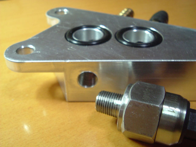
Drilled through the top into this recess in the ATF outlet port and fitted
a K-Thermo temperature sensor directly in the TC/ATF outlet stream.
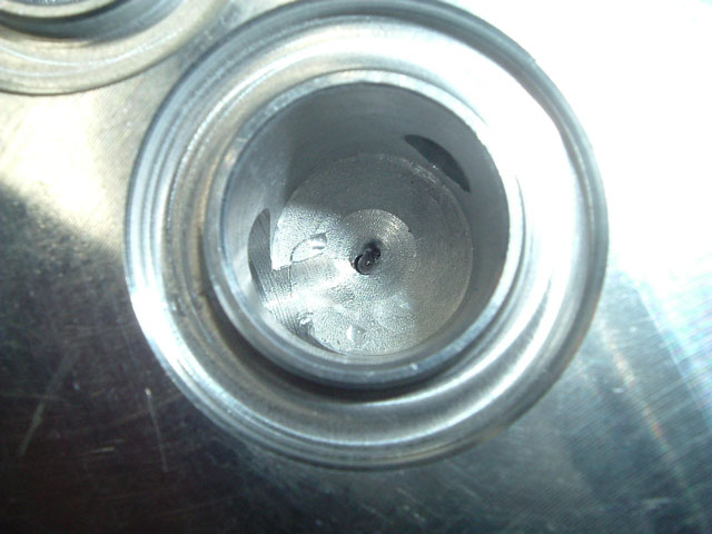
Made a cover plate for the top to seal the temperature sensor.
Went over kill so the SOB should not leak.
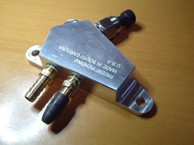
Partly installed in the vehicle - neat, no extra connections, pipes or clips,
no fluid fittings to get knocked and the pressure sensor cable unplugs from the back,
The pressure sensor is completely clear of everything behind the adaptor.
I tapped the back of the Adaptor housing for a 30psi sensor.
Drilled through the top into this recess in the ATF outlet port and fitted
a K-Thermo temperature sensor directly in the TC/ATF outlet stream.
Made a cover plate for the top to seal the temperature sensor.
Went over kill so the SOB should not leak.
Partly installed in the vehicle - neat, no extra connections, pipes or clips,
no fluid fittings to get knocked and the pressure sensor cable unplugs from the back,
The pressure sensor is completely clear of everything behind the adaptor.
08-27-2014, 01:31 AM
#18
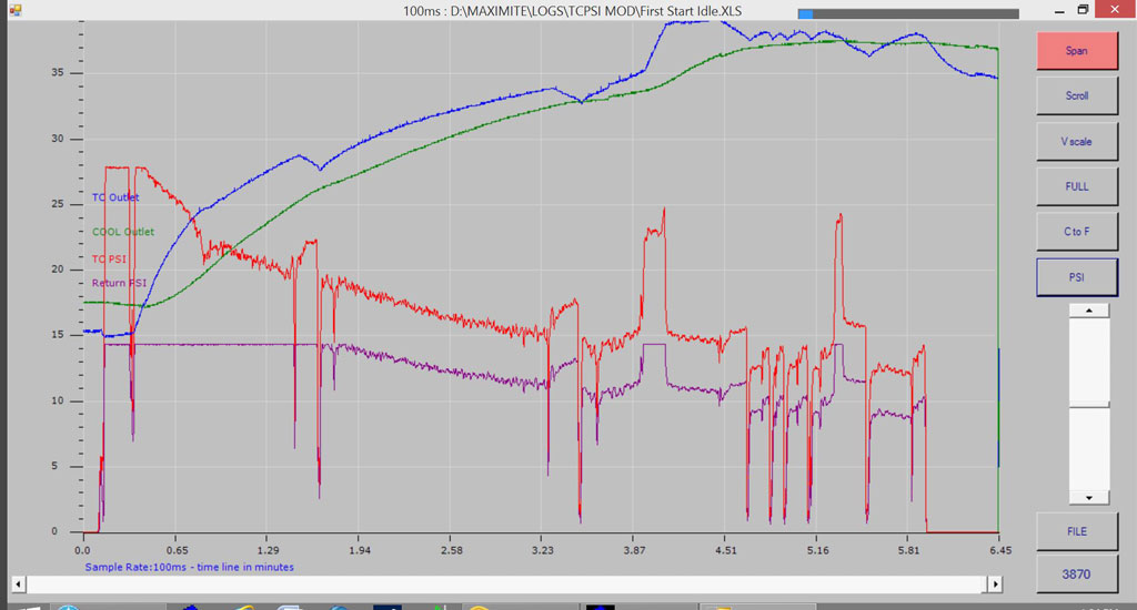
Cold start: Note that Return Pressure is a 15psi sensor and is flat-lined at 14.6 psi for the first 1.67 seconds. TC outlet pressure is a 30psi sensor and is also flat-lined at 28psi also due to a low 5 volt supply rail which will soon to be fixed
Note again how quickly pressure drops due to ATF viscosity change with heat, even at 35�C (95�F). Pressure difference is simply due to the 15psi sensors location close to the end of the ATF return input. In another graph it will be seen that when pressure readings are below 3psi - low flow rate - there is virtually no difference in psi between the sensors.
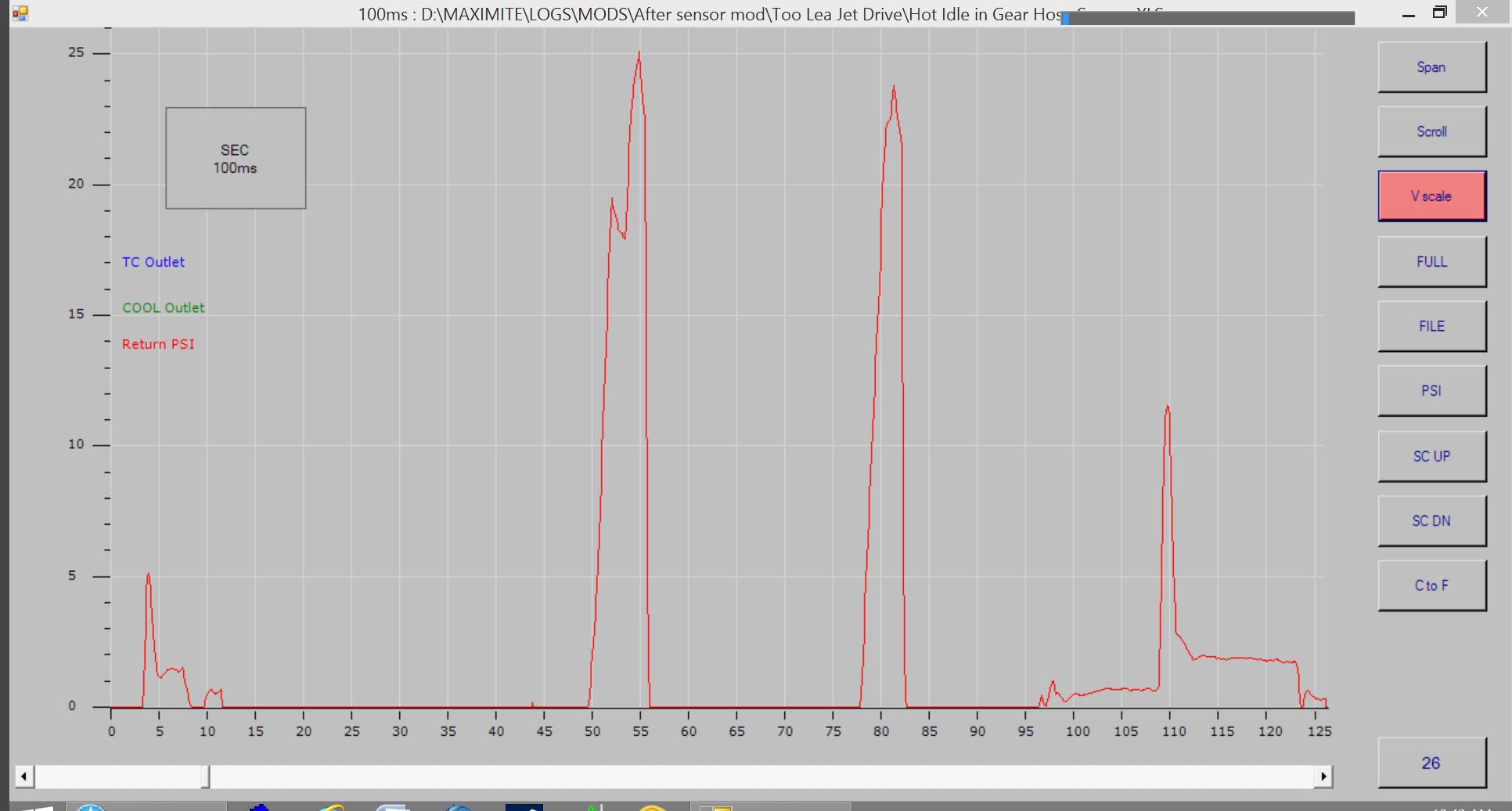
Peaks and troughs in the pressure readings: Very sharp short spikes are a result of gear selection N-1-2-D3-D vehicle is stationary the whole time in this graph. Longer rise and dips are RPM changes - in this case holding the vehicle braked in gear and bringing RPM up to 1200 RPM to see if the temperature sensor directly in the TC exit ATF flow can catch the sudden rise in TC temperature (it can).
This and other graphs highlight the fact that a temperature sensor mounted on a metal pipe CANNOT catch short temperature spikes in TC output temperature, notice how the cooler output sensor is completely smoothed out and delayed in any change AND this is not being influenced by the cooler as it is completely bypassed, there is 2 feet of hose separating the two sensors at this temperature. The cooler out sensor is bonded to a small aluminium pipe that is completely insulated from everything except the AT fluid, it is mounted in the rubber ATF return line and the complete assembly is encased in foil insulation, mounting a sensor to normal steel ATF lines that are attached to the transmission case would be even worse.
Just after 3.9 minutes (above) I bring the engine up to 1200 RPM in 2nd stationary, you can see TC output immediately rise.
__________________________
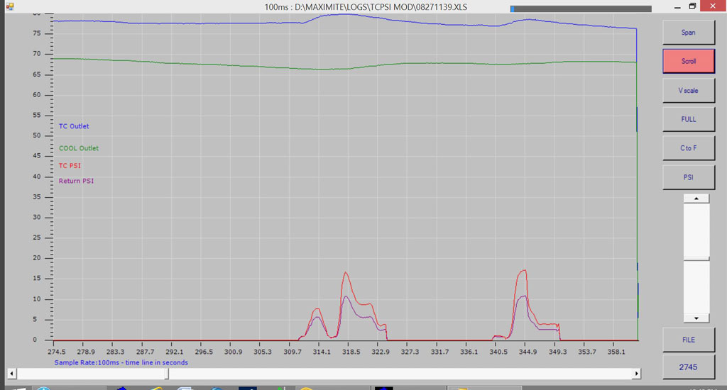
This is the first drive with the new setup, started shortly after the previous cold start graph. Once again 15psi sensor is flat-lined.
Notice TC output temps rise with moderate acceleration while pipe mounted cooler temperature probe delays and flattens any change, however in fairness the cooler bypass valve is now starting to crack open and dampen the temperature rise.
The graph below is hot idle 760 RPM - no air flow except for the AC fan. From 274 to 310 seconds the transmission is in D and although pressure shows zero there is still ATF flow through the TC and external cooler, at 310 seconds I bring engine up to 1200rpm to create more heat and then place the transmission in N and again bring up RPM to force a high ATF flow rate - TC output temperature increases by only 2�C and then drops, this is repeated again with the same result - there is sufficient flow rate at idle to keep the TC happy and cool whilst stopped in traffic in gear.
For more information see this link.
08-27-2014, 03:41 AM
#19
The low pressure at hot idle is consistent with published data on flow rates of 0.8 GPM under this condition in a good (and modified) transmission.
However I realised I had not posted the following here: This was a test on hot idle cooler circuit pressure I carried out.
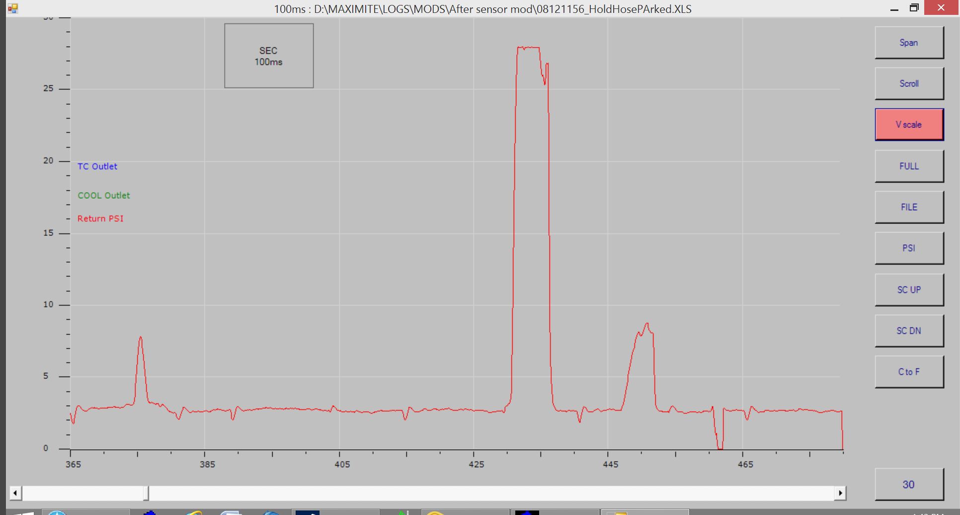
IN GEAR - HOT IDLE ATF 85�C. Squeezing the ATF return hose - after the inline pressure gauge - resulted in a jump from 0 psi to 25 psi on the gauge - flat-lined due to low 5volt. This indicates that although pressure measured at this point is reading zero under these conditions, the TC is still pushing fluid and will generate above 25 psi if needed to push fluid through the cooler line. Again, there was no sign of the internal cooler bypass valve fault attempting to bypass the TC or external cooler circuit even under this condition.
You have to ask yourself - What would it be like with ATF @ 120�C - 248�F ?
Graph: Cool ATF return hose squeezed tight (by hand) IN GEAR IDLE HOT (85�C) went from 0 to 25 PSI in order to maintain fluid flow.
However I realised I had not posted the following here: This was a test on hot idle cooler circuit pressure I carried out.
IN GEAR - HOT IDLE ATF 85�C. Squeezing the ATF return hose - after the inline pressure gauge - resulted in a jump from 0 psi to 25 psi on the gauge - flat-lined due to low 5volt. This indicates that although pressure measured at this point is reading zero under these conditions, the TC is still pushing fluid and will generate above 25 psi if needed to push fluid through the cooler line. Again, there was no sign of the internal cooler bypass valve fault attempting to bypass the TC or external cooler circuit even under this condition.
You have to ask yourself - What would it be like with ATF @ 120�C - 248�F ?
Graph: Cool ATF return hose squeezed tight (by hand) IN GEAR IDLE HOT (85�C) went from 0 to 25 PSI in order to maintain fluid flow.
08-27-2014, 05:52 PM
#22
Excessive Torque convertor heat is a function of many things. One is the design of the 5AT and is compounded by a flaw in the internal cooler circuit that becomes apparent as the transmission ages and under certain driving conditions, it has less to do with the transmission cooler but can still be controlled to some degree with appropriate changes. Another is due to other design flaws that can cause higher ATF temperatures than the OEM cooler was initially designed for - or did Honda know they had a problem before designing this circuit and releasing the 5AT?. The purpose of testing was to find a low cost logical means to effectively monitor the TC over the life of the vehicle and to check if a transmission was effected by the internal cooler flaw. Not getting caught in the middle of a 2 week cross country trip with low pressure or an (unknown) ATF overheat condition was also a factor. Cooler testing with only the OEM cooler, then with a big external cooler in series and finally with only a big external cooler and temperature bypass and taking detailed measurements along the way was an attempt to get to the bottom of just how effective "some" OEM setups are (I only have one 5AT to test) and if in fact the OEM cooler really is needed to stabilise or control the ATF cooler system as has been suggested.
The following users liked this post:
Timthetoolman (08-27-2014)
08-30-2014, 06:18 PM
#24
Link to more information - Currently a work in progress Thoughts and humble opinions could change as more testing and interpretation of data is carried out. I'll be sure to post an update here for those of us still interested in this sort of thing.
08-30-2014, 09:26 PM
#25
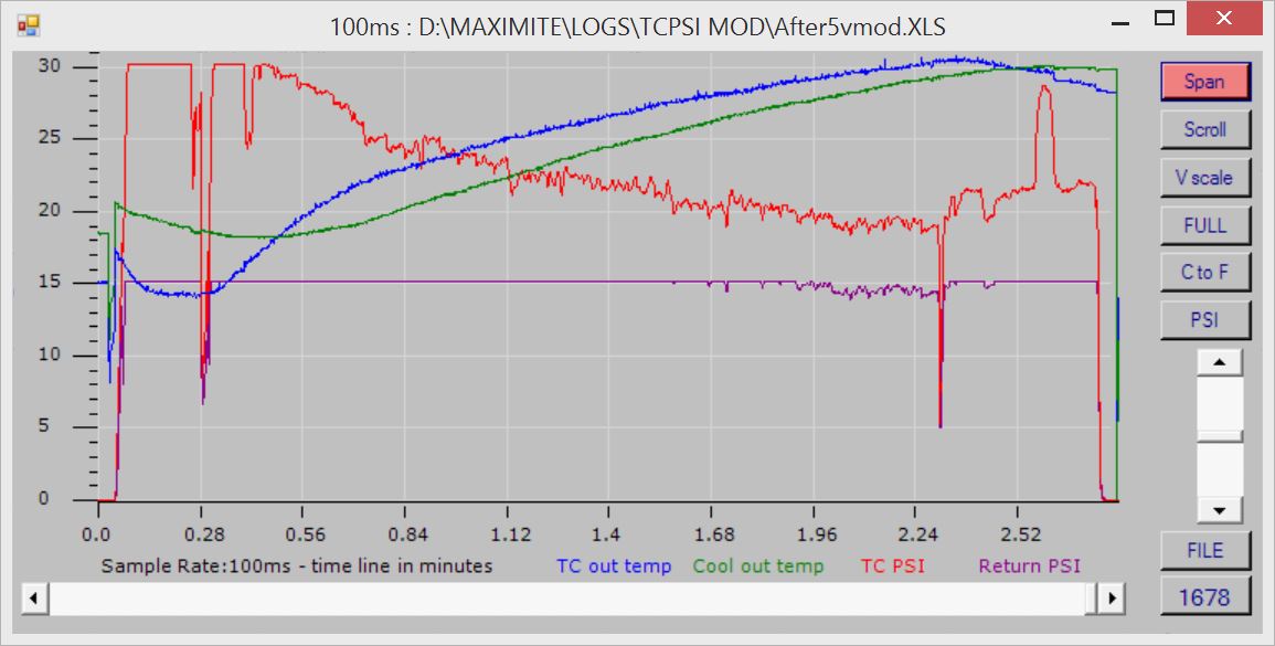
Just for interest: This is the graph I mentioned above. Notice at start up 0.0 to 0.56 how the Sensor in the cool outlet cannot track fast duration ATF temperature changes due to hysteresis created by the indirect mounting of the probe to the fluid. Both sensors are identical and both locations see the same ATF temperature until around 40�C when the temperature bypass valve starts to slightly crack open.
At 0.28 minutes the vehicle is placed into Drive. Vehicle is idling @ 720 rpm and stationary until 2.24 where it's placed into Park, RPM was raised for a second in Park at 2.34.
Note again the Return PSI reading is via a 15psi sensor so it's flat-lined most of the time in this graph.
The drop in pressure as fluid thins with heat is clearly seen here and we only get to 30�C.
09-02-2014, 11:07 PM
#26
Two hour drive - mixture of slow traffic and 70MPH cruise with TC locked. Overall fairly even temps once the cooler bypass opens.
As said many times before, there will be a large temperature divergence across the cooler as flow rate slows with pressure drop. With higher flow rates the outlet temperature is also higher (less temp diff across the cooler) but transmission bulk temperature stays the same - as it should. FYI OEM transmission sensor was hovering around 170 �F. Outside temperature reached 82 �F.
I've shown the graph in �F this time.
High red PSI is traffic and lots of low gear acceleration. Flat periods at around 5psi are 70mph cruise with the occasional psi spike being a gear change/acceleration for various reasons.
Last edited by Mkarl; 09-02-2014 at 11:10 PM.
09-06-2014, 11:06 PM
#27
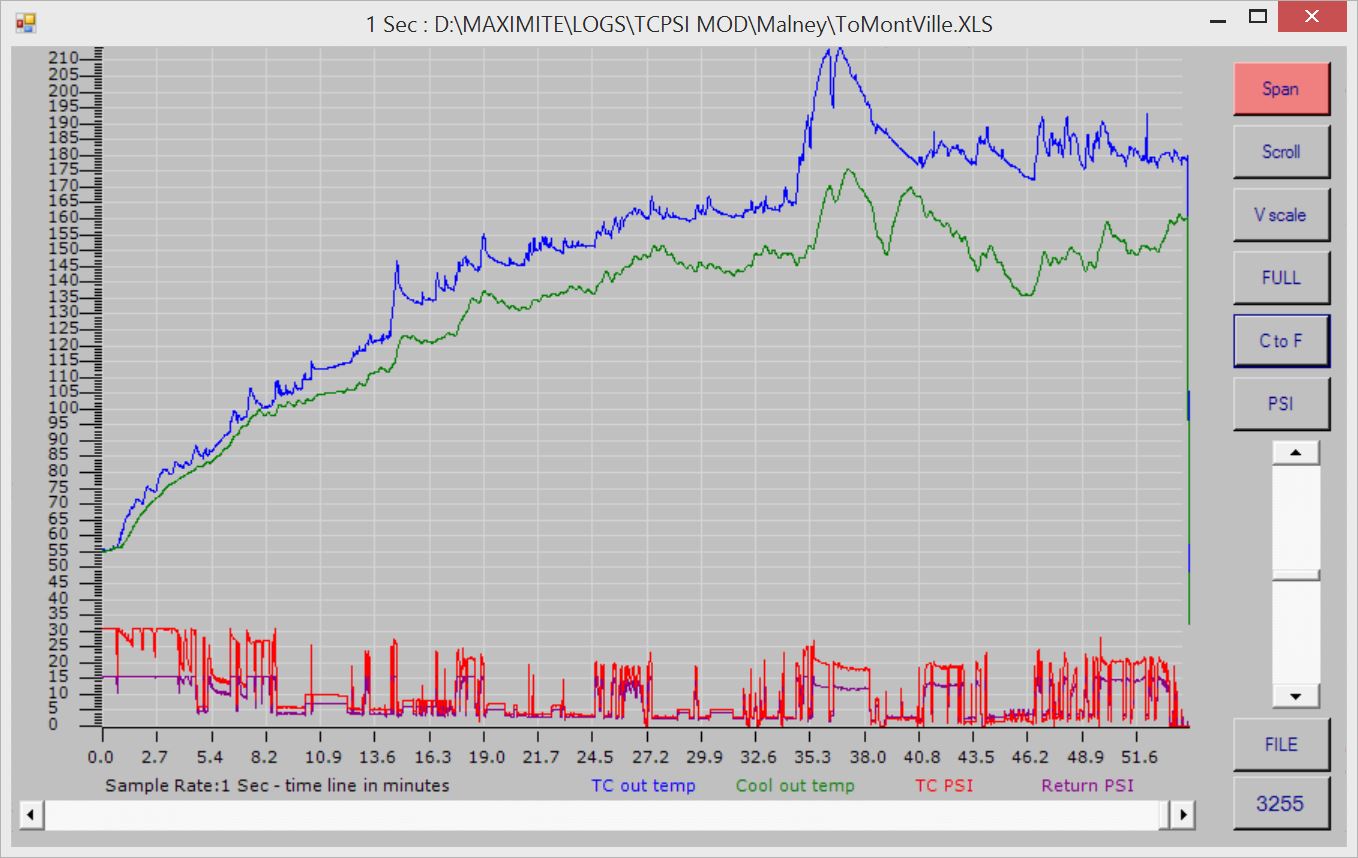
For anyone interested: Driving in hilly terrain, climbing to 1400ft with a major part of that climb in 4 minutes @ 50 mph. I's a very steep grade and when descending I lock the transmission in 3rd, I'm often on the brakes to hold speed at the posted limit - ears pop 3 to 4 times on the way down. Outside temp was 59�F at the start of the day, around 78�F on the climb, very fine sunny weather.
As a side note: I have been searching for data and going over other posted graphs from Honda owners for the past few weeks, with what I have measured along with results from my pressure testing, I noticed posted graph and data plots often showed ATF doing things in the 4AT/5AT cooler circuit that are impossible - I will point out my reservations on that data later.
BTW I'm in no way degrading the effort or results of these owners nor saying anything against these owners! They have done the best they could with what they had at the time, just as I'm trying to do - None had the advantage of cooler line pressure sensors - they were making educated guesses as to what was happening in the external cooler circuit and in the absence of available information were also underestimating loss of accuracy, response flattening and delays caused by mounting methods used for the sensors.
Back to the climb: I went 1/2 way up the very steep section with the vehicle in Drive, something I don't normally do on this or any long steep climb, but I wanted to test TC generated heat between 5th, 4th and 3rd on this climb.
NOTE: Transmission ATF / TC outlet is a 1/2 inch from the K thermo temperature head - this tiny sensor in inside an adaptor housing that removes the OEM warmer, the sensor is completely insulated from the surrounding metal housing - ATF sprays / flows straight at the sensor, it's flooded and instantly shows TC outlet ATF temperature with +/- 2.2� accuracy, the sensor head is rated to 1300�F.
As the vehicle started climbing this very steep road, ATF from the TC went from 65�F to 212�F in under 2 minutes, transmission was in Drive and it auto shifted from 5th to 4th. Engine had enough RPM and plenty of torque to easily hold 50mph on part throttle in 4th, engine management and TCU were not interested in downshifting to 3rd.
At 36 minutes (on the graph) I reach a short flat stretch of road for 15 seconds, RPM drops as it shifts up to 5th - Notice how fast the K-Thermo responds: First to a short sudden drop in TC pressure (no flow over the sensor) as the up-shift takes place, then to the reduced TC load as lower temperature bulk ATF flows at a very low rate through the cooler circuit and over the temperature sensor, this appears to lower TC ATF temperature by 20�F in a very short time - did I mention the sensor is insulated from EVERYTHING but the ATF - proof for any doubters.
I then change into 3rd before the start of the next steep climb, from that point on the vehicle stays in 3rd gear, still climbing the same steep grade @ 50mph @ around 3,400 RPM, TC exit temperature rises with higher ATF flow (3rd gear) then stabilises, ATF temperature comes down fairly quickly as heat output from the TC starts to drop and is cooled by bulk ATF low temperature, ATF temps drops 20�F before the grade flattens out and once again I shift into Drive on a more gentle slope, further steep climbs are made in 3rd and the temperature averages 180�F for the remainder of the climb.
Less slippage and therefore less heat generated by the TC because of increased engine RPM and a gear ratio that better matches engine speed (TC Input) to TC Output speed, resulting in less rotational speed difference across the Torque Convertor (TC).
I have always overridden any automatic (428 Cobra Jet BIG BLOCK with wall to wall torque included) as I refuse to LUG any motor below 3000 RPM on this kind of grade.
Because of incorrect placement of sensors and sample rates used by owners, either by trying to fit long trip data onto a hand held display device with little memory or sample rate limitations imposed by the device itself, none of the published data shows this instant change in heat so dramatically. A lot of data posted by owners is sampled at 1 to 10 minute intervals and because of the hysteresis created by the sensor mounting methods and location, dynamic changes in ATF temperature are flattened and delayed by minutes - or completely missed.
I have climbed for longer periods with similar grades in heat wave conditions in this Honda, I'm so thankful that I have always locked it in 3rd, sometimes 2nd with this 5AT.
Other users have measured ATF temperatures of over 260�F from the TC in mountain driving. They would have spiked far hotter than what they measured because of sensor placement and read sample rate.
The other thing to note is that bulk ATF temperatures ARE NOT increasing by that much in my transmission as this big plate & fin cooler is constantly trying to hold a 20�F difference between I/O fluid ports and at the peak TC heat output is showing almost a 45�F drop across this cooler, NOTE this is one case where I will highlight the cooler Delta temperature because flow rate in this instance is VERY HIGH - Delta temperatures across a cooler at low flow rates are meaningless. Bulk sump ATF temperature is under control in this setup.
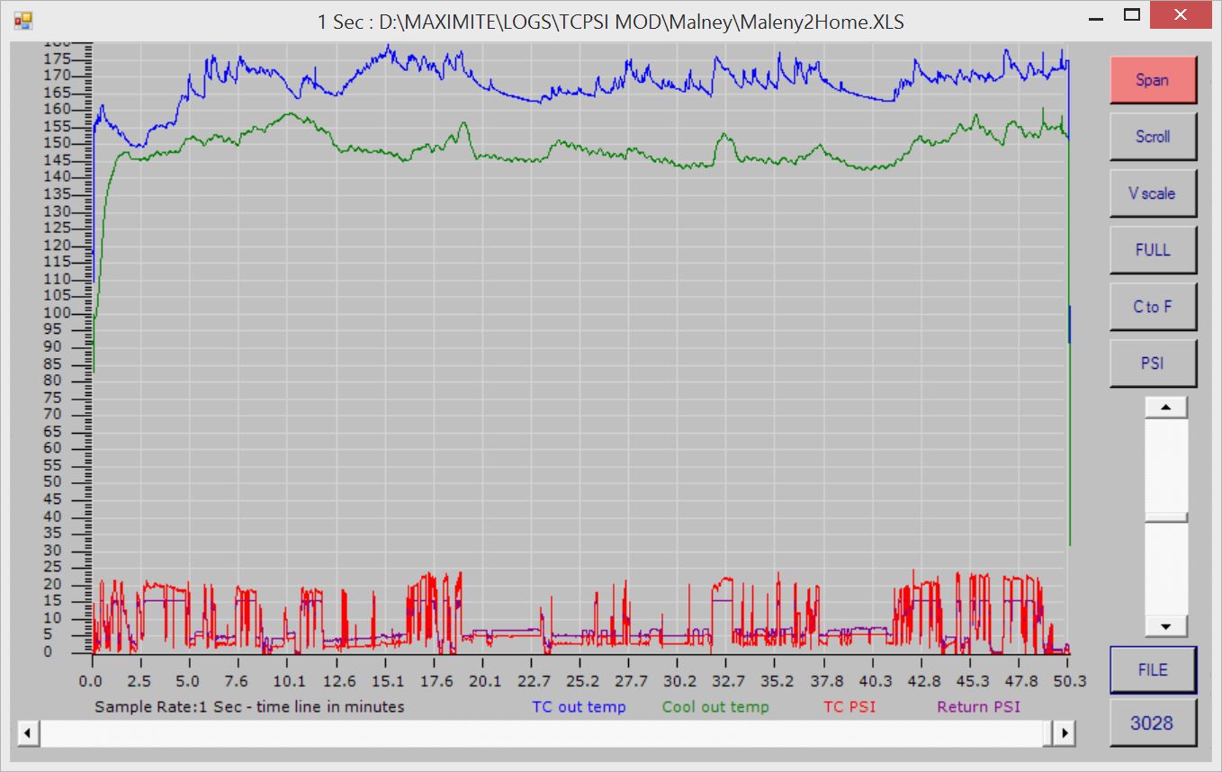
The return trip down the mountain was equally revealing and went completely against previous owner published data. There is data available from Odyssey and accord owners - again with a small "OEM fitted" front mounted cooler that supplements and is in series with the internal radiator ATF cooler or Hockey-Puck cooler. When driving downhill and when coasting in 4th or 5th with the TC locked, they reported temperature drops down to 130�F or less in some cases.
As I stated at the start, my vehicle was not coasting but in 3rd on the downhill run so the TC was still having to work, but likewise there was no big increase in temperatures as others have reported under this driving condition, TC outlet barely touched 180�F downhill under engine braking and averaged 170�F for the entire return trip. When cruising, the lowest temperature ATF went down to was 165�F before I hit a slight slope or slowed and accelerated for some other road conditions.
IMHO a temperature bypass on an external cooler is absolutely needed - even WITH AN OEM WARMER in circuit. Measurements I have taken on this G7 style OEM Hockey Puck cooler/warmer show that it's pretty much useless unless you live in sub zero climates, and we need someone to actually measure and prove how effective it is in this condition. Published data by other owners with OEM radiator tank mounted coolers and a small OEM external cooler show the same result - like the hockey-puck unit, the in-tank cooler appears to be too small to control anything but long term (very long term) ATF temperature variations, and only ATF temperatures that are NOT constantly changing by a significant amount.
Driving in hilly terrain, climbing to 1400ft with a major part of that climb in 4 minutes @ 50 mph. I's a very steep grade and when descending I lock the transmission in 3rd, I'm often on the brakes to hold speed at the posted limit - ears pop 3 to 4 times on the way down. Outside temp was 59�F at the start of the day, around 78�F on the climb, very fine sunny weather.
As a side note: I have been searching for data and going over other posted graphs from Honda owners for the past few weeks, with what I have measured along with results from my pressure testing, I noticed posted graph and data plots often showed ATF doing things in the 4AT/5AT cooler circuit that are impossible - I will point out my reservations on that data later.
BTW I'm in no way degrading the effort or results of these owners nor saying anything against these owners! They have done the best they could with what they had at the time, just as I'm trying to do - None had the advantage of cooler line pressure sensors - they were making educated guesses as to what was happening in the external cooler circuit and in the absence of available information were also underestimating loss of accuracy, response flattening and delays caused by mounting methods used for the sensors.
Back to the climb: I went 1/2 way up the very steep section with the vehicle in Drive, something I don't normally do on this or any long steep climb, but I wanted to test TC generated heat between 5th, 4th and 3rd on this climb.
NOTE: Transmission ATF / TC outlet is a 1/2 inch from the K thermo temperature head - this tiny sensor in inside an adaptor housing that removes the OEM warmer, the sensor is completely insulated from the surrounding metal housing - ATF sprays / flows straight at the sensor, it's flooded and instantly shows TC outlet ATF temperature with +/- 2.2� accuracy, the sensor head is rated to 1300�F.
As the vehicle started climbing this very steep road, ATF from the TC went from 65�F to 212�F in under 2 minutes, transmission was in Drive and it auto shifted from 5th to 4th. Engine had enough RPM and plenty of torque to easily hold 50mph on part throttle in 4th, engine management and TCU were not interested in downshifting to 3rd.
At 36 minutes (on the graph) I reach a short flat stretch of road for 15 seconds, RPM drops as it shifts up to 5th - Notice how fast the K-Thermo responds: First to a short sudden drop in TC pressure (no flow over the sensor) as the up-shift takes place, then to the reduced TC load as lower temperature bulk ATF flows at a very low rate through the cooler circuit and over the temperature sensor, this appears to lower TC ATF temperature by 20�F in a very short time - did I mention the sensor is insulated from EVERYTHING but the ATF - proof for any doubters.
I then change into 3rd before the start of the next steep climb, from that point on the vehicle stays in 3rd gear, still climbing the same steep grade @ 50mph @ around 3,400 RPM, TC exit temperature rises with higher ATF flow (3rd gear) then stabilises, ATF temperature comes down fairly quickly as heat output from the TC starts to drop and is cooled by bulk ATF low temperature, ATF temps drops 20�F before the grade flattens out and once again I shift into Drive on a more gentle slope, further steep climbs are made in 3rd and the temperature averages 180�F for the remainder of the climb.
Less slippage and therefore less heat generated by the TC because of increased engine RPM and a gear ratio that better matches engine speed (TC Input) to TC Output speed, resulting in less rotational speed difference across the Torque Convertor (TC).
I have always overridden any automatic (428 Cobra Jet BIG BLOCK with wall to wall torque included) as I refuse to LUG any motor below 3000 RPM on this kind of grade.
Because of incorrect placement of sensors and sample rates used by owners, either by trying to fit long trip data onto a hand held display device with little memory or sample rate limitations imposed by the device itself, none of the published data shows this instant change in heat so dramatically. A lot of data posted by owners is sampled at 1 to 10 minute intervals and because of the hysteresis created by the sensor mounting methods and location, dynamic changes in ATF temperature are flattened and delayed by minutes - or completely missed.
I have climbed for longer periods with similar grades in heat wave conditions in this Honda, I'm so thankful that I have always locked it in 3rd, sometimes 2nd with this 5AT.
Other users have measured ATF temperatures of over 260�F from the TC in mountain driving. They would have spiked far hotter than what they measured because of sensor placement and read sample rate.
The other thing to note is that bulk ATF temperatures ARE NOT increasing by that much in my transmission as this big plate & fin cooler is constantly trying to hold a 20�F difference between I/O fluid ports and at the peak TC heat output is showing almost a 45�F drop across this cooler, NOTE this is one case where I will highlight the cooler Delta temperature because flow rate in this instance is VERY HIGH - Delta temperatures across a cooler at low flow rates are meaningless. Bulk sump ATF temperature is under control in this setup.
The return trip down the mountain was equally revealing and went completely against previous owner published data. There is data available from Odyssey and accord owners - again with a small "OEM fitted" front mounted cooler that supplements and is in series with the internal radiator ATF cooler or Hockey-Puck cooler. When driving downhill and when coasting in 4th or 5th with the TC locked, they reported temperature drops down to 130�F or less in some cases.
As I stated at the start, my vehicle was not coasting but in 3rd on the downhill run so the TC was still having to work, but likewise there was no big increase in temperatures as others have reported under this driving condition, TC outlet barely touched 180�F downhill under engine braking and averaged 170�F for the entire return trip. When cruising, the lowest temperature ATF went down to was 165�F before I hit a slight slope or slowed and accelerated for some other road conditions.
IMHO a temperature bypass on an external cooler is absolutely needed - even WITH AN OEM WARMER in circuit. Measurements I have taken on this G7 style OEM Hockey Puck cooler/warmer show that it's pretty much useless unless you live in sub zero climates, and we need someone to actually measure and prove how effective it is in this condition. Published data by other owners with OEM radiator tank mounted coolers and a small OEM external cooler show the same result - like the hockey-puck unit, the in-tank cooler appears to be too small to control anything but long term (very long term) ATF temperature variations, and only ATF temperatures that are NOT constantly changing by a significant amount.
Test data shows that when stationary in gear, the OEM cooler (Tank or Hockey Puck) can help with ATF temperatures that can climb way up over 220 �F, sometime to 260 �F, but IMHO this ONLY happens when you don't have sufficient air flow over a "suitable sized" external cooler. I have no OEM cooler - No extra cooler fan BUT the Climate control is always on in my vehicle and the AC fan creates sufficient air flow to hold ATF temperature down or make temperatures drop if the vehicle is placed into Neutral when stationary for long periods.
However there is more to this than meets the eye! The design of the 5AT and another design feature (flaw) in some AT's can cause ATF to STOP flowing through the cooler and TC circuit when ATF is hot and the vehicle is stationary in gear. However flow rate is also very low with just HOT ATF and the hotter ATF gets the lower the flow rate becomes, especially as the transmission ages. It's easy to overcome when stationary if you know it's happening, it's been flagged by transmission rebuilders before and I wonder if it's a hidden major contributor to some of the TC failure and lock codes we see as our 5AT ages?
I would be very careful with a heavy load (EG towing) in 4th and 5th without the TC locked - There will be very low flow rate through the TC and cooler in OD gears - and it rapidly decreases with heat - so what looks like moderate holding temperatures can be incorrect and artificially lowered by insufficient ATF flow needed to overcome heat being pulled away from the sensors because of compromised installation and mounting locations.
The transmission case measured 155�F after a two hour trip. At very low ATF flow rates, attaching a thermo couple to a metal ATF line that is also attached to the transmission or clamped in the engine bay can result in the thermo couple readings being influenced by the outside temperature of the pipe, it's slowly being pulled down to that 155�F case temperature instead of the internal fluid temperature.
The graph below shown just how dynamic TC output is and how quickly it rises: The two spikes of ATF temperature are 3 seconds each in duration and are a result of being in D in 5th up two moderate grades at 50 mph. There was almost a 25�F spike in TC output, but an instant return to normal temperature as my bulk ATF temperature is, of course, totally unaffected by these short spikes - still you don't want overall bulk ATF temperatures at or over 220�F as some owners have measured. This is why some ATF cooling systems show high TC ATF temperatures coming down slowly over a very long time frame, overall ATF temperature is just too high to begin with.
You see it repeated and preached for years on Honda forums that bulk ATF sump temperature is the only reading you need to measure or concern yourself with in a transmission - what absolute nonsense - some of these posters really should stop doing Google searches and quoting "slush box transmission search results" as Honda AT facts.
BTW After a few seconds of TC lock or when travelling along a flat road under very little throttle in D3, bulk ATF temperature in only a few degrees less than indicated TC outlet temperatures, if the TC is locked or I/O speed differences across the TC are small, then what you see is bulk ATF temperature. The transmission produces very little heat in other conditions, the only time this would not be true would be with a slipping clutch pack, but T rise would be gradual as it's a small volume of fluid coating the clutch packs that is being super heated and fried causing total ATF volume to be degraded quite quickly, more so if a TC is turning blue from heat - as they do!
As a side note: I have been searching for data and going over other posted graphs from Honda owners for the past few weeks, with what I have measured along with results from my pressure testing, I noticed posted graph and data plots often showed ATF doing things in the 4AT/5AT cooler circuit that are impossible - I will point out my reservations on that data later.
BTW I'm in no way degrading the effort or results of these owners nor saying anything against these owners! They have done the best they could with what they had at the time, just as I'm trying to do - None had the advantage of cooler line pressure sensors - they were making educated guesses as to what was happening in the external cooler circuit and in the absence of available information were also underestimating loss of accuracy, response flattening and delays caused by mounting methods used for the sensors.
Back to the climb: I went 1/2 way up the very steep section with the vehicle in Drive, something I don't normally do on this or any long steep climb, but I wanted to test TC generated heat between 5th, 4th and 3rd on this climb.
NOTE: Transmission ATF / TC outlet is a 1/2 inch from the K thermo temperature head - this tiny sensor in inside an adaptor housing that removes the OEM warmer, the sensor is completely insulated from the surrounding metal housing - ATF sprays / flows straight at the sensor, it's flooded and instantly shows TC outlet ATF temperature with +/- 2.2� accuracy, the sensor head is rated to 1300�F.
As the vehicle started climbing this very steep road, ATF from the TC went from 65�F to 212�F in under 2 minutes, transmission was in Drive and it auto shifted from 5th to 4th. Engine had enough RPM and plenty of torque to easily hold 50mph on part throttle in 4th, engine management and TCU were not interested in downshifting to 3rd.
At 36 minutes (on the graph) I reach a short flat stretch of road for 15 seconds, RPM drops as it shifts up to 5th - Notice how fast the K-Thermo responds: First to a short sudden drop in TC pressure (no flow over the sensor) as the up-shift takes place, then to the reduced TC load as lower temperature bulk ATF flows at a very low rate through the cooler circuit and over the temperature sensor, this appears to lower TC ATF temperature by 20�F in a very short time - did I mention the sensor is insulated from EVERYTHING but the ATF - proof for any doubters.
I then change into 3rd before the start of the next steep climb, from that point on the vehicle stays in 3rd gear, still climbing the same steep grade @ 50mph @ around 3,400 RPM, TC exit temperature rises with higher ATF flow (3rd gear) then stabilises, ATF temperature comes down fairly quickly as heat output from the TC starts to drop and is cooled by bulk ATF low temperature, ATF temps drops 20�F before the grade flattens out and once again I shift into Drive on a more gentle slope, further steep climbs are made in 3rd and the temperature averages 180�F for the remainder of the climb.
Less slippage and therefore less heat generated by the TC because of increased engine RPM and a gear ratio that better matches engine speed (TC Input) to TC Output speed, resulting in less rotational speed difference across the Torque Convertor (TC).
I have always overridden any automatic (428 Cobra Jet BIG BLOCK with wall to wall torque included) as I refuse to LUG any motor below 3000 RPM on this kind of grade.
Because of incorrect placement of sensors and sample rates used by owners, either by trying to fit long trip data onto a hand held display device with little memory or sample rate limitations imposed by the device itself, none of the published data shows this instant change in heat so dramatically. A lot of data posted by owners is sampled at 1 to 10 minute intervals and because of the hysteresis created by the sensor mounting methods and location, dynamic changes in ATF temperature are flattened and delayed by minutes - or completely missed.
I have climbed for longer periods with similar grades in heat wave conditions in this Honda, I'm so thankful that I have always locked it in 3rd, sometimes 2nd with this 5AT.
Other users have measured ATF temperatures of over 260�F from the TC in mountain driving. They would have spiked far hotter than what they measured because of sensor placement and read sample rate.
The other thing to note is that bulk ATF temperatures ARE NOT increasing by that much in my transmission as this big plate & fin cooler is constantly trying to hold a 20�F difference between I/O fluid ports and at the peak TC heat output is showing almost a 45�F drop across this cooler, NOTE this is one case where I will highlight the cooler Delta temperature because flow rate in this instance is VERY HIGH - Delta temperatures across a cooler at low flow rates are meaningless. Bulk sump ATF temperature is under control in this setup.
The return trip down the mountain was equally revealing and went completely against previous owner published data. There is data available from Odyssey and accord owners - again with a small "OEM fitted" front mounted cooler that supplements and is in series with the internal radiator ATF cooler or Hockey-Puck cooler. When driving downhill and when coasting in 4th or 5th with the TC locked, they reported temperature drops down to 130�F or less in some cases.
As I stated at the start, my vehicle was not coasting but in 3rd on the downhill run so the TC was still having to work, but likewise there was no big increase in temperatures as others have reported under this driving condition, TC outlet barely touched 180�F downhill under engine braking and averaged 170�F for the entire return trip. When cruising, the lowest temperature ATF went down to was 165�F before I hit a slight slope or slowed and accelerated for some other road conditions.
IMHO a temperature bypass on an external cooler is absolutely needed - even WITH AN OEM WARMER in circuit. Measurements I have taken on this G7 style OEM Hockey Puck cooler/warmer show that it's pretty much useless unless you live in sub zero climates, and we need someone to actually measure and prove how effective it is in this condition. Published data by other owners with OEM radiator tank mounted coolers and a small OEM external cooler show the same result - like the hockey-puck unit, the in-tank cooler appears to be too small to control anything but long term (very long term) ATF temperature variations, and only ATF temperatures that are NOT constantly changing by a significant amount.
Driving in hilly terrain, climbing to 1400ft with a major part of that climb in 4 minutes @ 50 mph. I's a very steep grade and when descending I lock the transmission in 3rd, I'm often on the brakes to hold speed at the posted limit - ears pop 3 to 4 times on the way down. Outside temp was 59�F at the start of the day, around 78�F on the climb, very fine sunny weather.
As a side note: I have been searching for data and going over other posted graphs from Honda owners for the past few weeks, with what I have measured along with results from my pressure testing, I noticed posted graph and data plots often showed ATF doing things in the 4AT/5AT cooler circuit that are impossible - I will point out my reservations on that data later.
BTW I'm in no way degrading the effort or results of these owners nor saying anything against these owners! They have done the best they could with what they had at the time, just as I'm trying to do - None had the advantage of cooler line pressure sensors - they were making educated guesses as to what was happening in the external cooler circuit and in the absence of available information were also underestimating loss of accuracy, response flattening and delays caused by mounting methods used for the sensors.
Back to the climb: I went 1/2 way up the very steep section with the vehicle in Drive, something I don't normally do on this or any long steep climb, but I wanted to test TC generated heat between 5th, 4th and 3rd on this climb.
NOTE: Transmission ATF / TC outlet is a 1/2 inch from the K thermo temperature head - this tiny sensor in inside an adaptor housing that removes the OEM warmer, the sensor is completely insulated from the surrounding metal housing - ATF sprays / flows straight at the sensor, it's flooded and instantly shows TC outlet ATF temperature with +/- 2.2� accuracy, the sensor head is rated to 1300�F.
As the vehicle started climbing this very steep road, ATF from the TC went from 65�F to 212�F in under 2 minutes, transmission was in Drive and it auto shifted from 5th to 4th. Engine had enough RPM and plenty of torque to easily hold 50mph on part throttle in 4th, engine management and TCU were not interested in downshifting to 3rd.
At 36 minutes (on the graph) I reach a short flat stretch of road for 15 seconds, RPM drops as it shifts up to 5th - Notice how fast the K-Thermo responds: First to a short sudden drop in TC pressure (no flow over the sensor) as the up-shift takes place, then to the reduced TC load as lower temperature bulk ATF flows at a very low rate through the cooler circuit and over the temperature sensor, this appears to lower TC ATF temperature by 20�F in a very short time - did I mention the sensor is insulated from EVERYTHING but the ATF - proof for any doubters.
I then change into 3rd before the start of the next steep climb, from that point on the vehicle stays in 3rd gear, still climbing the same steep grade @ 50mph @ around 3,400 RPM, TC exit temperature rises with higher ATF flow (3rd gear) then stabilises, ATF temperature comes down fairly quickly as heat output from the TC starts to drop and is cooled by bulk ATF low temperature, ATF temps drops 20�F before the grade flattens out and once again I shift into Drive on a more gentle slope, further steep climbs are made in 3rd and the temperature averages 180�F for the remainder of the climb.
Less slippage and therefore less heat generated by the TC because of increased engine RPM and a gear ratio that better matches engine speed (TC Input) to TC Output speed, resulting in less rotational speed difference across the Torque Convertor (TC).
I have always overridden any automatic (428 Cobra Jet BIG BLOCK with wall to wall torque included) as I refuse to LUG any motor below 3000 RPM on this kind of grade.
Because of incorrect placement of sensors and sample rates used by owners, either by trying to fit long trip data onto a hand held display device with little memory or sample rate limitations imposed by the device itself, none of the published data shows this instant change in heat so dramatically. A lot of data posted by owners is sampled at 1 to 10 minute intervals and because of the hysteresis created by the sensor mounting methods and location, dynamic changes in ATF temperature are flattened and delayed by minutes - or completely missed.
I have climbed for longer periods with similar grades in heat wave conditions in this Honda, I'm so thankful that I have always locked it in 3rd, sometimes 2nd with this 5AT.
Other users have measured ATF temperatures of over 260�F from the TC in mountain driving. They would have spiked far hotter than what they measured because of sensor placement and read sample rate.
The other thing to note is that bulk ATF temperatures ARE NOT increasing by that much in my transmission as this big plate & fin cooler is constantly trying to hold a 20�F difference between I/O fluid ports and at the peak TC heat output is showing almost a 45�F drop across this cooler, NOTE this is one case where I will highlight the cooler Delta temperature because flow rate in this instance is VERY HIGH - Delta temperatures across a cooler at low flow rates are meaningless. Bulk sump ATF temperature is under control in this setup.
The return trip down the mountain was equally revealing and went completely against previous owner published data. There is data available from Odyssey and accord owners - again with a small "OEM fitted" front mounted cooler that supplements and is in series with the internal radiator ATF cooler or Hockey-Puck cooler. When driving downhill and when coasting in 4th or 5th with the TC locked, they reported temperature drops down to 130�F or less in some cases.
As I stated at the start, my vehicle was not coasting but in 3rd on the downhill run so the TC was still having to work, but likewise there was no big increase in temperatures as others have reported under this driving condition, TC outlet barely touched 180�F downhill under engine braking and averaged 170�F for the entire return trip. When cruising, the lowest temperature ATF went down to was 165�F before I hit a slight slope or slowed and accelerated for some other road conditions.
IMHO a temperature bypass on an external cooler is absolutely needed - even WITH AN OEM WARMER in circuit. Measurements I have taken on this G7 style OEM Hockey Puck cooler/warmer show that it's pretty much useless unless you live in sub zero climates, and we need someone to actually measure and prove how effective it is in this condition. Published data by other owners with OEM radiator tank mounted coolers and a small OEM external cooler show the same result - like the hockey-puck unit, the in-tank cooler appears to be too small to control anything but long term (very long term) ATF temperature variations, and only ATF temperatures that are NOT constantly changing by a significant amount.
Test data shows that when stationary in gear, the OEM cooler (Tank or Hockey Puck) can help with ATF temperatures that can climb way up over 220 �F, sometime to 260 �F, but IMHO this ONLY happens when you don't have sufficient air flow over a "suitable sized" external cooler. I have no OEM cooler - No extra cooler fan BUT the Climate control is always on in my vehicle and the AC fan creates sufficient air flow to hold ATF temperature down or make temperatures drop if the vehicle is placed into Neutral when stationary for long periods.
However there is more to this than meets the eye! The design of the 5AT and another design feature (flaw) in some AT's can cause ATF to STOP flowing through the cooler and TC circuit when ATF is hot and the vehicle is stationary in gear. However flow rate is also very low with just HOT ATF and the hotter ATF gets the lower the flow rate becomes, especially as the transmission ages. It's easy to overcome when stationary if you know it's happening, it's been flagged by transmission rebuilders before and I wonder if it's a hidden major contributor to some of the TC failure and lock codes we see as our 5AT ages?
I would be very careful with a heavy load (EG towing) in 4th and 5th without the TC locked - There will be very low flow rate through the TC and cooler in OD gears - and it rapidly decreases with heat - so what looks like moderate holding temperatures can be incorrect and artificially lowered by insufficient ATF flow needed to overcome heat being pulled away from the sensors because of compromised installation and mounting locations.
The transmission case measured 155�F after a two hour trip. At very low ATF flow rates, attaching a thermo couple to a metal ATF line that is also attached to the transmission or clamped in the engine bay can result in the thermo couple readings being influenced by the outside temperature of the pipe, it's slowly being pulled down to that 155�F case temperature instead of the internal fluid temperature.
The graph below shown just how dynamic TC output is and how quickly it rises: The two spikes of ATF temperature are 3 seconds each in duration and are a result of being in D in 5th up two moderate grades at 50 mph. There was almost a 25�F spike in TC output, but an instant return to normal temperature as my bulk ATF temperature is, of course, totally unaffected by these short spikes - still you don't want overall bulk ATF temperatures at or over 220�F as some owners have measured. This is why some ATF cooling systems show high TC ATF temperatures coming down slowly over a very long time frame, overall ATF temperature is just too high to begin with.
You see it repeated and preached for years on Honda forums that bulk ATF sump temperature is the only reading you need to measure or concern yourself with in a transmission - what absolute nonsense - some of these posters really should stop doing Google searches and quoting "slush box transmission search results" as Honda AT facts.
BTW After a few seconds of TC lock or when travelling along a flat road under very little throttle in D3, bulk ATF temperature in only a few degrees less than indicated TC outlet temperatures, if the TC is locked or I/O speed differences across the TC are small, then what you see is bulk ATF temperature. The transmission produces very little heat in other conditions, the only time this would not be true would be with a slipping clutch pack, but T rise would be gradual as it's a small volume of fluid coating the clutch packs that is being super heated and fried causing total ATF volume to be degraded quite quickly, more so if a TC is turning blue from heat - as they do!
09-06-2014, 11:45 PM
#28
Apology for part double post above - Just came back to rectify it and as usual, 30 odd minutes later I can't edit my post. Perhaps I should just repost it.
Actually here is a link to the complete testing data, the above data obviously towards the end of the page in the link.
Link to ->Cooler Testing Data.html
Actually here is a link to the complete testing data, the above data obviously towards the end of the page in the link.
Link to ->Cooler Testing Data.html
Last edited by Mkarl; 09-06-2014 at 11:59 PM.
09-19-2014, 12:20 AM
#29
For anyone interested, I thought I'd post a small update here on a simple way to fit a very accurate K-thermocouple temperature sensor in the ATF line, one that is influenced only by the AT Fluid and not the engine compartment environment.
It again involves something like a Derale thermostat switch housing DERALE UNIVERSAL STANDARD SERIES IN-LINE FLUID THERMOSTAT -6 AN X -6 AN 13021 - on eBay. And something like an old (or new) air-duster fitting that's normally used with an air compressor.
I recently purchased a low cost Tap and Dye set that included a 1/8 NPT27T tap which fits the pressure sensor (if used) and also the air duster fitting, so off I went.
This housing had been drilled and tapped either side for both a Temperature and a pressure sensor .
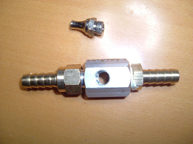
Housing drilled for fittings, air duster fitting with metal extension removed and K-thermocouple shown for size.
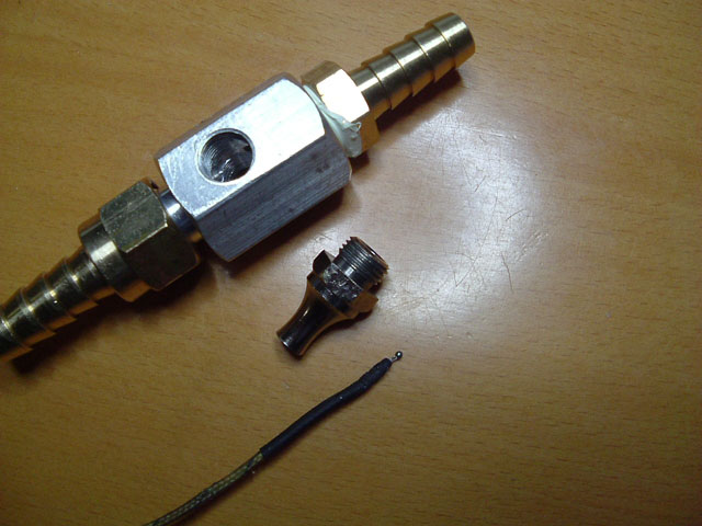
This gives you an idea of the size compared to 3/8 ATF hose.
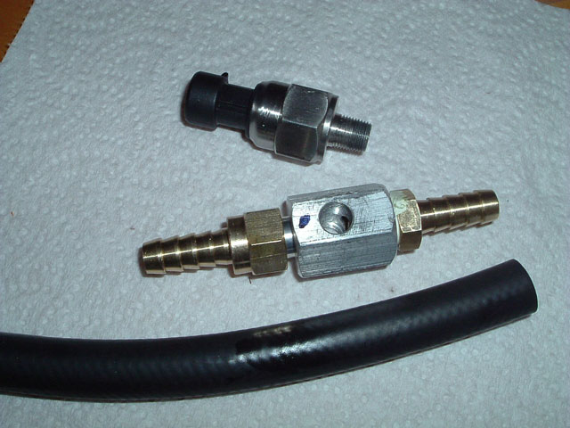
K-thermocouple mounted and sealed in the adaptor with high temperature silicone RTV.
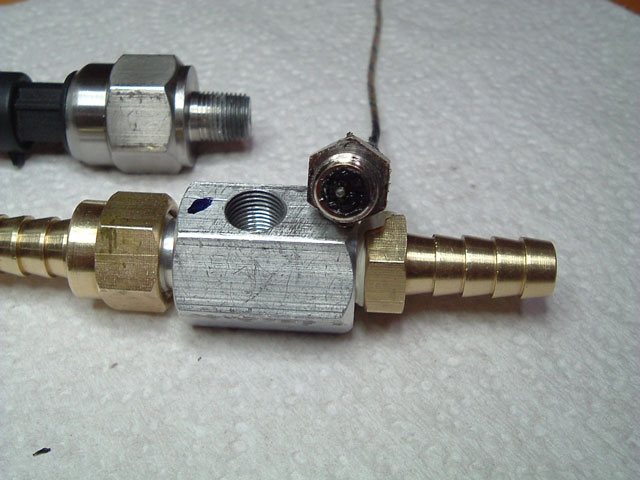
This is a work in progress and it's the first real recap of all current data and graphs. A lot of this data has been recorded and sampled at 0.10 second (100ms) intervals IE: 10 sensor samples per second, 600 samples per minute or 36,000 samples per hour. Compare this to most "long term" sample times of 1 to 10 minutes per reading and you can see that there is some very informative data, and when expanded out in my graphing software it gives a very detailed view of pressure and temperature every 0.10 of a second throughout daily driving sessions.
The following conclusions are based on this data and weeks spent going over numerous published data sets from owners, and some very hard to find published data by 4AT and 5AT transmission investigators. Hopefully it will make someone think about an ATF cooler installation in a different light.
I was going to post a recap on testing here, however it's quite long and I'm not sure there is that much interest anymore, so here is a link to the first round of thoughts/conclusions on this and other data. -> Link to Cooler Recap
It again involves something like a Derale thermostat switch housing DERALE UNIVERSAL STANDARD SERIES IN-LINE FLUID THERMOSTAT -6 AN X -6 AN 13021 - on eBay. And something like an old (or new) air-duster fitting that's normally used with an air compressor.
I recently purchased a low cost Tap and Dye set that included a 1/8 NPT27T tap which fits the pressure sensor (if used) and also the air duster fitting, so off I went.
This housing had been drilled and tapped either side for both a Temperature and a pressure sensor .
Housing drilled for fittings, air duster fitting with metal extension removed and K-thermocouple shown for size.
This gives you an idea of the size compared to 3/8 ATF hose.
K-thermocouple mounted and sealed in the adaptor with high temperature silicone RTV.
This is a work in progress and it's the first real recap of all current data and graphs. A lot of this data has been recorded and sampled at 0.10 second (100ms) intervals IE: 10 sensor samples per second, 600 samples per minute or 36,000 samples per hour. Compare this to most "long term" sample times of 1 to 10 minutes per reading and you can see that there is some very informative data, and when expanded out in my graphing software it gives a very detailed view of pressure and temperature every 0.10 of a second throughout daily driving sessions.
The following conclusions are based on this data and weeks spent going over numerous published data sets from owners, and some very hard to find published data by 4AT and 5AT transmission investigators. Hopefully it will make someone think about an ATF cooler installation in a different light.
I was going to post a recap on testing here, however it's quite long and I'm not sure there is that much interest anymore, so here is a link to the first round of thoughts/conclusions on this and other data. -> Link to Cooler Recap
The following users liked this post:
Timthetoolman (09-20-2014)
09-26-2014, 04:26 AM
#30
Using the OEM ATF Sump temperature sensor.
A question that is often asked concerns the possibility of connecting directly to the V6 5AT Honda OEM ATF sump temperature sensor and using it to drive a separate temperature display - without affecting the signal going to the ECU.
First - the Sensor I measured is in my V6 5AT Accord, however as the 5AT in earlier models is basically the same then it's reasonable to assume they use the same sensor across most models.
First the good news - Yes it can be done.
The BAD news - I cannot find any data or specifications for this sensor. It's an NTC Thermistor and these things are a shit to use as they involve floating point maths and various manufacture data sets and curve information to convert what is a very nonlinear output into something that resembles temperature.
To overcome this lack of data I came up with a way to measure the Resistance and Voltage seen by the ECU/TCU as a function of the ATF T Sensor. I tabulated data for Voltage, Resistance and Temperature from [ - 20�C to 150�C ] in 5�C increments. I was hopeful that I could either come up with formula values to plug into published NTC Thermistor calculations - I gave up on that - or use the data of values to implement a voltage to temperature "lookup table" in software. That of course worked.
BTW, you can monitor the temperature sensor with $20 DVM, connect the negative lead to the transmission ground and the positive lead to the sensor signal cable. The voltage shown can be converted straight to Temperature with my lookup chart. Handy if you just want to get an idea of temperature to see how hot your trans gets under load. No need to purchase or install a sensor.
In my case I have ATF sump data fed to my existing data logging device and my Car computer 4 gauge temperature display. Just finished a quick test drive and it tracked perfectly.
I can now plot/graph ATF Torque Convert outlet, Cooler outlet and ATF Sump temperatures against Cooler line pressure in a very detailed way. This should help answer some of the speculation / arguments over the best ATF measuring locations in this 5AT.
If there is any interest in this or someone is interested in how this sensor is wired or operates then I'll post the relevant information.
The following users liked this post:
Slpr04UA6 (09-26-2014)
09-27-2014, 12:31 AM
#31
Mkarl--Thanks for all your testing and write ups! The summary found in your link is very interesting and I will look more closely at it again later.
You wrote "monitor the temperature sensor with $20 DVM, connect the negative lead to the transmission ground and the positive lead to the sensor signal cable." How can I find both of these connections and is this measuring sump temperature".
You wrote "monitor the temperature sensor with $20 DVM, connect the negative lead to the transmission ground and the positive lead to the sensor signal cable." How can I find both of these connections and is this measuring sump temperature".
09-27-2014, 12:44 AM
#32
The temp sensor connector located at the end of the transmission, remove the LH wheel to access the connector. There are two wires on the plug, one is ground. I said use the trans case as a ground so that you only have to tap into one wire instead of two. Either way is fine.
FYI The temp sensor has to be unplugged and the cable retainer and cover removed to expose one of the pressure switches when changing them.
LINK -> The first picture on the left shows the Grey connector
Yes this is ATF sump temperatures used by the TCU/ECU. The reason to use a DVM is because you need a relatively high impedance when measuring this lead, you don't want to affect the sensor voltage and throw off the readings to the ECU. A DVM is fine.
I'll be posting the look up table to convert Voltage to Temperature for this sensor in the near future.
The following 2 users liked this post by Mkarl:
pohljm (09-27-2014),
Timthetoolman (09-29-2014)
09-27-2014, 09:01 AM
#33
Road Racer / Solo Addict
Tons of info here, thanks OP, subscribed to read in detail!
09-28-2014, 04:59 AM
#34
I have uploaded my OEM ATF sensor Lookup Table and some general information on the sensor.
NOTE: You may have to refresh your Web browser if you have viewed this site recently.
Link to Lookup Table and preliminary information.
NOTE: You may have to refresh your Web browser if you have viewed this site recently.
Link to Lookup Table and preliminary information.
The following users liked this post:
EL BAN (09-28-2014)
09-28-2014, 08:28 PM
#35
FYI First run with the OEM sump sensor, Things to note are the OEM Sensor had a response time measured in seconds and the Pan (sump) temperatures change more slowly than the TC or cooler outlet temperatures AND those two sensors are Thermocouple devices and have a response time of a few milliseconds. The result is a stepped waveform from the OEM sensor, but gee it tracks well and does exactly what I thought.
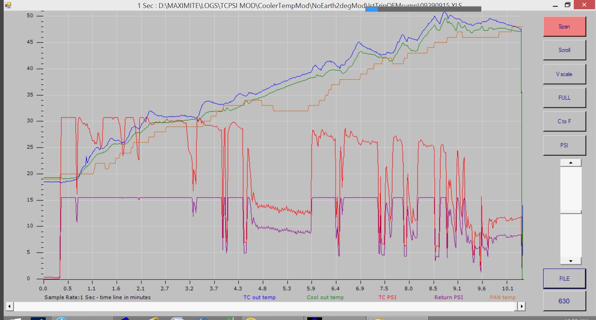
There is another graph that continues on from this here: Link to Lookup Table data and Second Graph
-
There is another graph that continues on from this here: Link to Lookup Table data and Second Graph
-
09-28-2014, 11:07 PM
#36
Further to the Graph in previous post 35:
Also of interest is Sump temperatures starting to come down @ 4.5 minutes as the transmission cruises in 5th even though ATF temperatures are still increasing. The Sensor is been influenced by the AT outer case being cooled 2� to 3� by high speed air flow over the case / sump under the influence of lowered ATF flow. It starts to rise again just before dropping to 3rd because of rising ATF temperatures and then higher ATF flow rate (which overcomes AT case influences) along with slower speed and heat increase from the TC as the vehicle accelerates up an incline.
IMHO this and the other graph in the links above disprove the idea a few people have of using the cooler outlet temperature as an indication of ATF temperatures and proves that the sump sensor CANNOT indicate short term "dangerous" TC outlet temperatures until the damage has been done AND it can be affected by AT case cooling during long cruise conditions with low ATF flow - this can cause even the OEM sump ATF sensor to indicate an artificially lowered ATF temperature.
It also reinforces my thoughts on the validity of reading TC outlet temperatures and that once the AT case is warmed to operating temperature, TC outlet temperature IS bulk ATF sump temperature ANYTIME the AT is not under load and obviously when cruising with the TC locked.
Last edited by Mkarl; 09-28-2014 at 11:15 PM.
09-29-2014, 02:16 PM
#37
Team Owner

Further to the Graph in previous post 35:
Also of interest is Sump temperatures starting to come down @ 4.5 minutes as the transmission cruises in 5th even though ATF temperatures are still increasing. The Sensor is been influenced by the AT outer case being cooled 2� to 3� by high speed air flow over the case / sump under the influence of lowered ATF flow. It starts to rise again just before dropping to 3rd because of rising ATF temperatures and then higher ATF flow rate (which overcomes AT case influences) along with slower speed and heat increase from the TC as the vehicle accelerates up an incline.
IMHO this and the other graph in the links above disprove the idea a few people have of using the cooler outlet temperature as an indication of ATF temperatures and proves that the sump sensor CANNOT indicate short term "dangerous" TC outlet temperatures until the damage has been done AND it can be affected by AT case cooling during long cruise conditions with low ATF flow - this can cause even the OEM sump ATF sensor to indicate an artificially lowered ATF temperature.
It also reinforces my thoughts on the validity of reading TC outlet temperatures and that once the AT case is warmed to operating temperature, TC outlet temperature IS bulk ATF sump temperature ANYTIME the AT is not under load and obviously when cruising with the TC locked.
Also of interest is Sump temperatures starting to come down @ 4.5 minutes as the transmission cruises in 5th even though ATF temperatures are still increasing. The Sensor is been influenced by the AT outer case being cooled 2� to 3� by high speed air flow over the case / sump under the influence of lowered ATF flow. It starts to rise again just before dropping to 3rd because of rising ATF temperatures and then higher ATF flow rate (which overcomes AT case influences) along with slower speed and heat increase from the TC as the vehicle accelerates up an incline.
IMHO this and the other graph in the links above disprove the idea a few people have of using the cooler outlet temperature as an indication of ATF temperatures and proves that the sump sensor CANNOT indicate short term "dangerous" TC outlet temperatures until the damage has been done AND it can be affected by AT case cooling during long cruise conditions with low ATF flow - this can cause even the OEM sump ATF sensor to indicate an artificially lowered ATF temperature.
It also reinforces my thoughts on the validity of reading TC outlet temperatures and that once the AT case is warmed to operating temperature, TC outlet temperature IS bulk ATF sump temperature ANYTIME the AT is not under load and obviously when cruising with the TC locked.
The following users liked this post:
csmeance (09-29-2014)
09-29-2014, 06:12 PM
#38
I just wanted to say that while I don't comment on your posts often, they're very much appreciated. It seems like I never have the time to properly comment so I just don't say anything at all but I did want to say thanks for all of the time you've taken to share your findings with us.
09-29-2014, 06:38 PM
#39
BTW for those interested here is the second part of the graph from post#35 above. It gives a better idea of OEM ATF sensor tracking once the Cooler Bypass valve opens at around 80�C [TC outlet temp]. Cooler outlet splits and drops way below Sump temperature and TC outlet matches OEM Sump sensor temperature whenever the TC is not generating heat - IE cruise locked or flat road easy driving with no start stop conditions. Note: Very hilly twisting road with lots of gear changing just after Bypass valve opens. I purposely left the trans in 4th, 5th instead of dropping to 3rd when climbing these hills to force the TC outlet temperatures up.
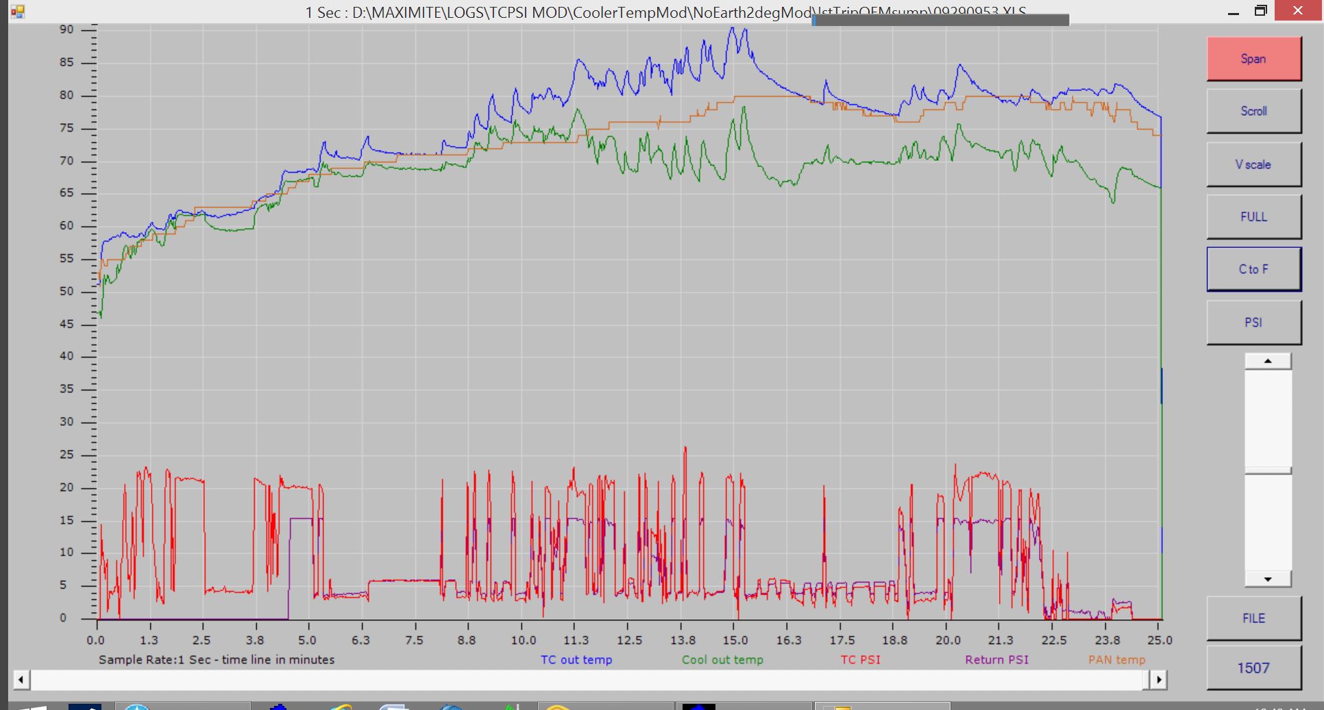
Last edited by Mkarl; 09-29-2014 at 06:42 PM.
09-29-2014, 10:48 PM
#40
Suzuka Master
Thanks IHC, and also to others who have added a thanks tick. Even if forum users don't agree with my analysis and conclusions of the data, at the very least it may make someone think, instead of listening to Google search answers and "I think responses" without meaningful data to back up those thoughts. Hopefully my sensor installation and locations should at last nullify the usual arguments and debates over the accuracy of sensor readings.
Keep it coming, because although I haven't quite figured out how to interpret the data, or what to do with the data this is some of the most in depth information about the fragile AT that we have. I have lost 3 total V6 AT's between Odyssey and TL. most had symptoms of high temps being part of the failure, or a result of the failure possibly?
