
DIY: Make a relay harness for your '07-'08 DRL's
 05-18-2013, 12:28 PM
#1
Engineer in Training
Thread Starter
DIY: Make a relay harness for your '07-'08 DRL's
I've been seeing more and more people purchasing LED Daytime Running Lights and having trouble installing them on their facelifted (07-08) TLs wondering why those with 04-06 TLs are installing just fine. The reason is that the 04-06 TL does NOT have daytime running lights, but instead have FOG lights. The reason for this is because the incandescent fog light bulbs can be powered at +6V where the LED bulbs need +12V in order to turn on since they don't dim like incandescents do.
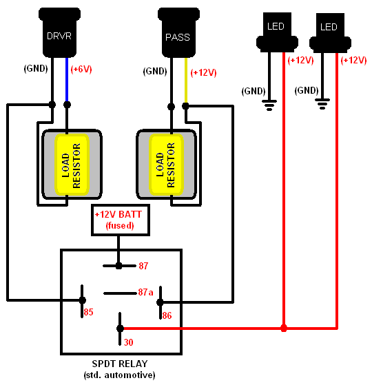
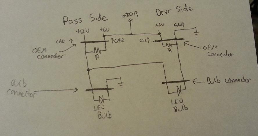
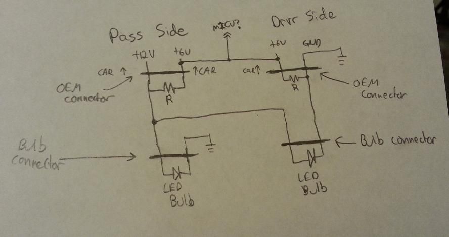
The FOG light circuit provides +12V and Ground on each light (wired to 12V in parallel) whereas the DRL circuit provides +12V and Ground on the passenger side and is "daisy-chained" to the drivers circuit (wired to 12V in series). What this does is effectively split the voltage between the two DRL so that each receives only +6V.
What the relay harness below does is use the ground from the Driver side light harness and the +12V from the Passenger side light as triggers for a relay. What the relay does is then provide +12V to the LED bulbs.
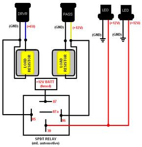
Note: I drew in Load Resistors as this will trick the car into thinking that it has the required (and working) bulbs connected to the DRL connections. This helps to prevent the DRL indicator from coming on in the dash/instrument cluster. They do NOT affect the functionality of the relay harness. They are there simply to keep the light from coming on and being annoying. If you choose not to use Load Resistors (as they can be added in later on), simply cut and tape off the Blue wire on the driver side and the Black wire on the Passenger side. Essentially what you're doing is using ONLY the Black(ground) from the driver side, and the Power(+12V) from the passenger side to engage the relay.
The connectors labelled "DRVR" and "PASS" are the MALE connectors shown below. These are what will plug into the vehicle's existing DRL sockets. The connectors labeled "LED" are the connector are the FEMALE connectors shown below.

Yes, you can buy a prebuilt harness, yes it may even cost you less. But if you're like me, and either have most of the items around or want to make one yourself so that you can run the wires exactly where you want, and have them exactly as long as you want or need then you can just follow my makeshift schematic above.
Hope this helps. Any questions, feel free to post here or PM me.
Cheers!
The FOG light circuit provides +12V and Ground on each light (wired to 12V in parallel) whereas the DRL circuit provides +12V and Ground on the passenger side and is "daisy-chained" to the drivers circuit (wired to 12V in series). What this does is effectively split the voltage between the two DRL so that each receives only +6V.
What the relay harness below does is use the ground from the Driver side light harness and the +12V from the Passenger side light as triggers for a relay. What the relay does is then provide +12V to the LED bulbs.
Note: I drew in Load Resistors as this will trick the car into thinking that it has the required (and working) bulbs connected to the DRL connections. This helps to prevent the DRL indicator from coming on in the dash/instrument cluster. They do NOT affect the functionality of the relay harness. They are there simply to keep the light from coming on and being annoying. If you choose not to use Load Resistors (as they can be added in later on), simply cut and tape off the Blue wire on the driver side and the Black wire on the Passenger side. Essentially what you're doing is using ONLY the Black(ground) from the driver side, and the Power(+12V) from the passenger side to engage the relay.
The connectors labelled "DRVR" and "PASS" are the MALE connectors shown below. These are what will plug into the vehicle's existing DRL sockets. The connectors labeled "LED" are the connector are the FEMALE connectors shown below.
Yes, you can buy a prebuilt harness, yes it may even cost you less. But if you're like me, and either have most of the items around or want to make one yourself so that you can run the wires exactly where you want, and have them exactly as long as you want or need then you can just follow my makeshift schematic above.
Hope this helps. Any questions, feel free to post here or PM me.
Cheers!

The following 2 users liked this post by LockDots:
BDoggPrelude (04-13-2014),
Vlad_Type_S (06-10-2014)
05-18-2013, 12:31 PM
#2
Race Director
iTrader: (8)
Very good information.
I think most people will buy the harness, though haha
I think most people will buy the harness, though haha
05-18-2013, 12:37 PM
#3
Engineer in Training
Thread Starter
05-19-2013, 05:15 AM
#5
Moderator
iTrader: (7)
When I got he ijdmtoy harness I took it apart and reverse engineered it. It's exactly as how you said in OP. it takes positive from one side and negative from one side and powers the relay. And the resistors are wired in parallel to get rid of the dash light. I always thought its very easy to make this harness, as an automotice relay is available anywhere. This is a good thread for people who aren't sure how the harness works.
The following users liked this post:
LockDots (05-19-2013)
04-11-2014, 06:51 PM
#6
Drifting
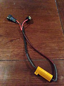
Searching for a solution I found this thread. I ordered a set of LED DRL's for our 07 TL and they came with an "error free" harness. After install, there is no DRL error but the LED's only light up halfway. Here is a picture of the harness supplied with the kit. Can I modify this harness to work as described above?
 04-11-2014, 07:07 PM
#7
Race Director
iTrader: (8)
Yes, you could.
Some extra wire (16 awg works fine), a relay, and some butt connectors and ring terminals and you'll have a harness.
Some extra wire (16 awg works fine), a relay, and some butt connectors and ring terminals and you'll have a harness.
Last edited by guitarplayer16; 04-11-2014 at 07:09 PM.
Trending Topics
04-12-2014, 06:43 PM
#8
Drifting
I attempted this today but failed.  I bought everything at Radio Shack. Only thing I did differently was I used a SPST relay instead of the SPDT as they did not have one in stock. I was told either one should work. I'm starting to think that may be the reason why it's not working. If I connect the power directly to the LED's they light up and there is no DRL error code but they do not turn off when the headlights come on. Hooked up through the relay, nothing comes on at all.
I bought everything at Radio Shack. Only thing I did differently was I used a SPST relay instead of the SPDT as they did not have one in stock. I was told either one should work. I'm starting to think that may be the reason why it's not working. If I connect the power directly to the LED's they light up and there is no DRL error code but they do not turn off when the headlights come on. Hooked up through the relay, nothing comes on at all.
04-12-2014, 07:52 PM
#9
Race Director
iTrader: (8)
I attempted this today but failed. I bought everything at Radio Shack. Only thing I did differently was I used a SPST relay instead of the SPDT as they did not have one in stock. I was told either one should work. I'm starting to think that may be the reason why it's not working. If I connect the power directly to the LED's they light up and there is no DRL error code but they do not turn off when the headlights come on. Hooked up through the relay, nothing comes on at all.
I bought everything at Radio Shack. Only thing I did differently was I used a SPST relay instead of the SPDT as they did not have one in stock. I was told either one should work. I'm starting to think that may be the reason why it's not working. If I connect the power directly to the LED's they light up and there is no DRL error code but they do not turn off when the headlights come on. Hooked up through the relay, nothing comes on at all.First, you'll probably want a SPDT relay.
Secondly, check to make sure your trigger source works. Use a multimeter and test pin 30 to see if it gets power once you turn your car on.
I assume you tapped into the triggers correctly?
Either tapping into your "error decoder" resistor's wire works, or tapping into the DRL wire would work also.
04-12-2014, 08:15 PM
#10
Drifting
Did a little more testing with a multimeter. Instead of using the ground from the resistors, like in the diagram, I grounded the relay directly to the chassis and finally got something out of the relay...but it works sporadically. It will work for a minute, turns DRL's off when turning on headlights and back on when headlights go off. Turn the car off and the relay stops working again. Checking with the multimeter, the only thing that ever changes is the power coming out of the relay. Any thoughts?
04-12-2014, 08:24 PM
#11
Race Director
iTrader: (8)
If the leads from the trigger wires going into the relay (pin 86) is hot but the output (pin 30) changes, I would get a SPDT relay and try to see if it works =)
Make sure all grounds are secure, also.
Make sure all grounds are secure, also.
04-12-2014, 11:16 PM
#12
Drifting
Also, I originally wired it like in the diagram above with the power supply from the battery going into #87 and the power out to the LED's coming from #30. This didn't work at all. After doing some testing and some input from a couple of people that know a lot more about this stuff then myself, I switched them so that the power supply goes into #30 and the output to the LED's comes from #87. With that arrangement it works intermittently at least. Don't know if the diagram above was labeled wrong or not. The diagram with both relays I have show the power supply should go into #30.
04-12-2014, 11:49 PM
#13
Race Director
iTrader: (8)
You're right - the diagram must be labeled wrong. 87 should usually go to the accessory that needs power and 30 usually goes to the power source.
Something definitely doesn't sound right - it should work, or it shouldn't. Not 20% of the time.
Not sure what else to say other than check the taps to the trigger wire.
I would also try switching the positive from the resistor to 85 and ground the 86 to the chassis or resistor negative wire.
Something definitely doesn't sound right - it should work, or it shouldn't. Not 20% of the time.
Not sure what else to say other than check the taps to the trigger wire.
I would also try switching the positive from the resistor to 85 and ground the 86 to the chassis or resistor negative wire.
Last edited by guitarplayer16; 04-12-2014 at 11:52 PM.
04-12-2014, 11:53 PM
#14
Drifting
I actually did ground the #86 to the chassis. It didn't work using the ground from the driver side resistor.
Could it be that the 12V relay is just not constantly picking up the signal from the 6V DRL module?
Could it be that the 12V relay is just not constantly picking up the signal from the 6V DRL module?
04-13-2014, 12:05 AM
#15
Drifting

I have a circuit schematic that I created from 2 years ago for these 9005's.. but I won't show you because acurazine has too many haters.
Hope you figure it out by yourself.

Hope you figure it out by yourself.
Last edited by Chad05TL; 04-13-2014 at 12:07 AM.
04-13-2014, 12:07 AM
#16
Drifting
by the way, I did not buy someone else's little black box. And I still have these 2 yrs later and no melting or discoloration
04-13-2014, 12:16 AM
#17
Drifting
and my DRLs come on automatically when the key turns ON.. And the DRLs go off AUTOMATICALLY when I turn the headlights ON.
And soon, even that will be automated by my "auto light sensor".. (look it up)
And soon, even that will be automated by my "auto light sensor".. (look it up)
04-13-2014, 12:22 AM
#18
Race Director
iTrader: (8)
Did you make your taps for the trigger using the resistor or the OEM DRL wires?
04-13-2014, 12:23 AM
#19
Drifting

Why even post if you have nothing worthwhile to contribute?
04-13-2014, 12:25 AM
#20
Drifting
04-13-2014, 12:37 AM
#21
Race Director
iTrader: (8)
Make sure you tap into the positive wire for the one side, and the negative wire for the other side. It'll ensure proper trigger supply.
Last time you tried, you must have tapped both negative, or both positive; hence nothing happened.
I can assure you it will work. Logically it should work.

Let me know how it goes.
04-13-2014, 12:41 AM
#22
Drifting
I would try tapping into the OEM wire.
Make sure you tap into the positive wire for the one side, and the negative wire for the other side. It'll ensure proper trigger supply.
Last time you tried, you must have tapped both negative, or both positive; hence nothing happened.
I can assure you it will work. Logically it should work.
Let me know how it goes.
04-13-2014, 12:50 AM
#23
Race Director
iTrader: (8)
That's strange the ground didn't work.
Good luck tomorrow
Good luck tomorrow
04-13-2014, 05:28 PM
#25
Hope you figure it out by yourself."
Thanks for being so helpful and contributing to this thread with your useless post.
Just reading your post and looking at your signature clearly shows your so full of yourself.
IM THE FIRST TO DO THIS.
IM THE FIRST TO DO THAT.
I WANT EVERYONE TO KNOW THAT I WAS THE FIRST FIRST FIRST
but i wont tell anyone how to do anything because I want to be the first and only.
The following 2 users liked this post by vietxquangstah:
DeathMetal (06-13-2014),
kev08wdp (06-13-2014)
04-13-2014, 05:55 PM
#26
Drifting
^^^The funny thing is the picture he posted doesn't even look like it has LED's. They look like the stock yellowish DRL's to me. Some peoples' children. 
Moving on. After some rewiring, trial and error and testing with the multimeter, I got it to work...I think. There was one little hiccup, of course when I was trying to show it off to my wife. I was cycling back and forth between the headlights and DRL's and after a couple times the DRL's stopped coming on. The ignition was only turned to the accessory position and the battery is on its last leg so I think it was actually an issue with the battery. (The battery was not the problem yesterday. I was testing with the car on and off and getting the issues either way). I checked and rechecked with the car running and have yet to have the intermittent problem again.
The ground from the driver side resistor to the relay was one issue I was having. I started off the day with the ground going from the resistor to the relay and it would not work. Added a ground straight from the chassis to the relay along with the one from the resistor and it still did not work. Unhooked the ground from the resistor leaving the relay grounded to the chassis and it worked immediately.
I don't know. I'm no electrical expert. This is just the setup that worked for me. If I start having issues after this I'll probably just order the iJDMtoy harness and be done with it. I probably should have just done that anyway because I probably spent almost as much money in materials to build the harness as it would have cost me to just order the iJDMtoy one. My biggest issue was that the car was apart and I wanted to get it done this weekend and not have to wait.
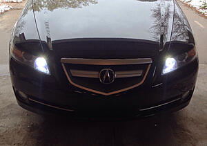
Anyway, thank you everybody for your help and to the OP for making this write-up. Here's a picture of the final results.
Moving on. After some rewiring, trial and error and testing with the multimeter, I got it to work...I think. There was one little hiccup, of course when I was trying to show it off to my wife. I was cycling back and forth between the headlights and DRL's and after a couple times the DRL's stopped coming on. The ignition was only turned to the accessory position and the battery is on its last leg so I think it was actually an issue with the battery. (The battery was not the problem yesterday. I was testing with the car on and off and getting the issues either way). I checked and rechecked with the car running and have yet to have the intermittent problem again.
The ground from the driver side resistor to the relay was one issue I was having. I started off the day with the ground going from the resistor to the relay and it would not work. Added a ground straight from the chassis to the relay along with the one from the resistor and it still did not work. Unhooked the ground from the resistor leaving the relay grounded to the chassis and it worked immediately.
I don't know. I'm no electrical expert. This is just the setup that worked for me. If I start having issues after this I'll probably just order the iJDMtoy harness and be done with it. I probably should have just done that anyway because I probably spent almost as much money in materials to build the harness as it would have cost me to just order the iJDMtoy one. My biggest issue was that the car was apart and I wanted to get it done this weekend and not have to wait.
Anyway, thank you everybody for your help and to the OP for making this write-up. Here's a picture of the final results.
 04-13-2014, 06:12 PM
#28
Drifting
I used these:
http://www.ebay.com/itm/171283599857...84.m1439.l2649
They're pretty bright. I'm happy with them.
http://www.ebay.com/itm/171283599857...84.m1439.l2649
They're pretty bright. I'm happy with them.
The following users liked this post:
vietxquangstah (04-13-2014)
04-13-2014, 08:03 PM
#29
Race Director
iTrader: (8)
Glad you got it working - in the future, if you want to test the DRLs, just put the key to the ON position (two clicks). The DRL doesn't work on Accessory, not by factory 
The following users liked this post:
BDoggPrelude (04-13-2014)
04-13-2014, 09:32 PM
#30
Drifting
That's what I meant, wrong wording. One click short of turning the engine on. I forgot ACC is one click.
04-13-2014, 09:54 PM
#31
Engineer in Training
Thread Starter
You're right - the diagram must be labeled wrong. 87 should usually go to the accessory that needs power and 30 usually goes to the power source.
Something definitely doesn't sound right - it should work, or it shouldn't. Not 20% of the time.
Not sure what else to say other than check the taps to the trigger wire.
I would also try switching the positive from the resistor to 85 and ground the 86 to the chassis or resistor negative wire.
Something definitely doesn't sound right - it should work, or it shouldn't. Not 20% of the time.
Not sure what else to say other than check the taps to the trigger wire.
I would also try switching the positive from the resistor to 85 and ground the 86 to the chassis or resistor negative wire.
^^^The funny thing is the picture he posted doesn't even look like it has LED's. They look like the stock yellowish DRL's to me. Some peoples' children.
Moving on. After some rewiring, trial and error and testing with the multimeter, I got it to work...I think. There was one little hiccup, of course when I was trying to show it off to my wife. I was cycling back and forth between the headlights and DRL's and after a couple times the DRL's stopped coming on. The ignition was only turned to the accessory position and the battery is on its last leg so I think it was actually an issue with the battery. (The battery was not the problem yesterday. I was testing with the car on and off and getting the issues either way). I checked and rechecked with the car running and have yet to have the intermittent problem again.
The ground from the driver side resistor to the relay was one issue I was having. I started off the day with the ground going from the resistor to the relay and it would not work. Added a ground straight from the chassis to the relay along with the one from the resistor and it still did not work. Unhooked the ground from the resistor leaving the relay grounded to the chassis and it worked immediately.
I don't know. I'm no electrical expert. This is just the setup that worked for me. If I start having issues after this I'll probably just order the iJDMtoy harness and be done with it. I probably should have just done that anyway because I probably spent almost as much money in materials to build the harness as it would have cost me to just order the iJDMtoy one. My biggest issue was that the car was apart and I wanted to get it done this weekend and not have to wait.
Anyway, thank you everybody for your help and to the OP for making this write-up. Here's a picture of the final results.
Sorry I didn't see this until just now, I could have helped you out sooner but I just started a new job and had a busy weekend.
The following users liked this post:
BDoggPrelude (04-13-2014)
06-10-2014, 09:52 PM
#32
Registered Bike Offender
iTrader: (3)
Awesome thread!!! Thanks for linking it up gplayer!
First of all, ^ Fuck this guy right in the pussy.
Second of all, I came here to ask how the car actually determines if the DRLs are out. I know that the bulbs are in series meaning 12V gets split for 6V on each bulb as explained in OP. I know that the middle signal (6V) goes to a control module or something. Does this mean that the only requirement to trick the car into thinking the DRLs are OK is 6V on the blue wire that's in between the bulbs? Or does it actually somehow monitor the power consumption of the bulbs as well?
If all it needs is 6V, then I can build a harness that doesn't even need any relays or high power load resistors. If it does monitor power consumption, then I can still build one that doesn't need relays...
Why wouldn't this work with a high R value that draws very little current?
Edit: The +12V is actually the DRL voltage, not to be confused with battery voltage.
Last edited by Vlad_Type_S; 06-10-2014 at 09:57 PM.
06-12-2014, 11:09 PM
#33
Registered Bike Offender
iTrader: (3)
Just going to bump this real quick... I'm in the process of returning stuff/placing another VLEDs order and was hoping to get you awesome guys' feedback on the circuit up there. If you think this is possible, I won't order the VLEDs harness.
06-12-2014, 11:26 PM
#34
Race Director
iTrader: (8)
I would assume it monitors the consumption of the bulb, as to tell if the bulb is out or not.
06-12-2014, 11:50 PM
#35
Moderator
iTrader: (7)
Awesome thread!!! Thanks for linking it up gplayer!
First of all, ^ Fuck this guy right in the pussy.
Second of all, I came here to ask how the car actually determines if the DRLs are out. I know that the bulbs are in series meaning 12V gets split for 6V on each bulb as explained in OP. I know that the middle signal (6V) goes to a control module or something. Does this mean that the only requirement to trick the car into thinking the DRLs are OK is 6V on the blue wire that's in between the bulbs? Or does it actually somehow monitor the power consumption of the bulbs as well?
If all it needs is 6V, then I can build a harness that doesn't even need any relays or high power load resistors. If it does monitor power consumption, then I can still build one that doesn't need relays...
Why wouldn't this work with a high R value that draws very little current?
Edit: The +12V is actually the DRL voltage, not to be confused with battery voltage.
It's like the turn signals, the DRL needs to see a load (6ohm IIRC) on both plugs to operate properly.
The diagram as shown in the OP is actually probably as simple as the harness can get, its straight forward and works great. You can make it yourself if you wanted. All you would need is a $5 relay, a pair of resistors($5), and a couple wires.
The way your diagram shows would not work, I'm sure. There is no 12v signal on the plugs.
The following users liked this post:
Vlad_Type_S (06-13-2014)
06-13-2014, 10:34 AM
#36
Registered Bike Offender
iTrader: (3)
Thanks for the replies guys! Now my curiosity is peaked. I'm going to have to run some tests and characterize this system. 
Hmm, that's a good point. I notice the specs of all of the 9005 VLEDs buls to have an operating voltage of 12V-24V and a forward voltage of 9V+. Not sure what's in that little box that comes with the 2100LM MT-G2 bulbs, but it allows it to run with a 6V input.
This is the $50 dollar question I want to answer haha. The turn signals have a little shunt somewhere that produces a small, but specifically correct voltage drop when the turn signal bulbs are operating properly, right? If my understanding is correct, it's basically a resistor network. I read that thread about replacing the shunt with a different resistor to eliminate hyperflashing with LED bulbs. How clever!!!
I'll definitely take a second look. I do think there is 12V wrt GND on one of the plugs, but that's only based on schematic inspection and not any actual testing. I'll whip out the DMM this weekend. 
At this point, the only thing I'm not sure about is whether to use the MT-G2 3000LM bulbs or the far less brighter 850LM 9005 bulbs. I don't want them to be too bright...
At this point, the only thing I'm not sure about is whether to use the MT-G2 3000LM bulbs or the far less brighter 850LM 9005 bulbs. I don't want them to be too bright...
06-15-2014, 06:29 PM
#38
i acutally have a harness that ijdmtoy tested on my car. Everything lights up perfect with no error code. Unfortunately i disconnected the harness when i was doing the UCM cause the guy from ijdmtoy has zip tied it to random things which i didnt like. After finishing the UCM i reconnected the harness only to find out nothing works. This i did not understand only cause i was reconnecting everything as it was. So since everything stopped working i had to completely go back to my stock DRLs. I have the harness with the leds sitting in my room. I would contact ijdmtoy this week but i will not have my car so they can reconnect everything.
Here is the picture of the harness in question
- Top left you can see the resistor that connects to the harness on the car.
- Followed by the black wire for ground.
- Red wire with fuse connects to battery.
- The resistor on the right connects to the stock harness on car.
Any everything should work but it didnt when i reconnected everything.

if you guys need more detailed pictures please let me know and i will do my best to take more pictures and upload.
Here is the picture of the harness in question
- Top left you can see the resistor that connects to the harness on the car.
- Followed by the black wire for ground.
- Red wire with fuse connects to battery.
- The resistor on the right connects to the stock harness on car.
Any everything should work but it didnt when i reconnected everything.
if you guys need more detailed pictures please let me know and i will do my best to take more pictures and upload.
05-28-2015, 11:36 PM
#40
Drifting
A helm ETM will tell you how it determines when the DRL is out.. And it will also tell you if the DRL's are in series or parallel.
And someone above was correct, I do not have LED's. I think the OEM bulbs look better even though it is more tricky to get bulbs working correctly than LED's
And someone above was correct, I do not have LED's. I think the OEM bulbs look better even though it is more tricky to get bulbs working correctly than LED's